
Related Manuals for Elenco Electronics M-1006K


Summary of Contents for Elenco Electronics M-1006K
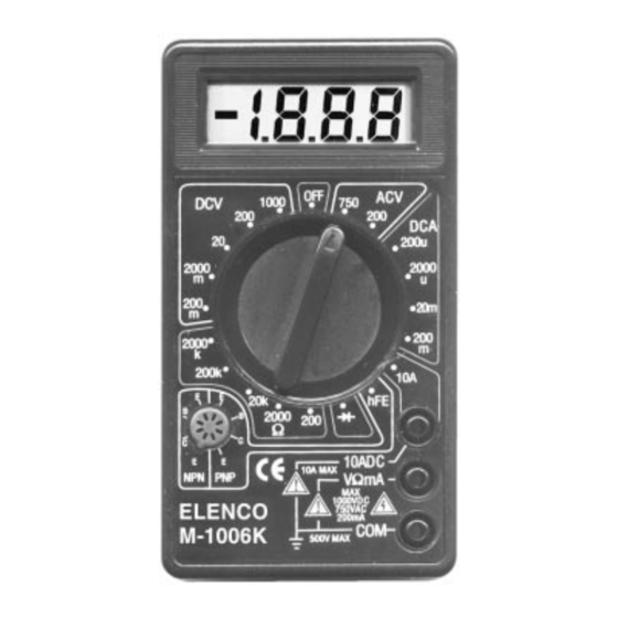
- Page 1 DIGITAL MULTIMETER KIT MODEL M-1006K Assembly and Instruction Manual Elenco Electronics, Inc. Copyright © 2001 Elenco Electronics, Inc. 753096...
-
Page 2: Parts List
If you are a student, and any parts are missing or damaged, please see instructor or bookstore. If you purchased this meter kit from a distributor, catalog, etc., please contact Elenco Electronics (address/phone/e-mail is at the back of this manual) for additional assistance, if needed. DO NOT contact your place of purchase as they will not be able to help you. -
Page 3: Parts Identification
PARTS IDENTIFICATION Resistors Shunt Wire Selector Knob Potentiometer Ball Bearing IDENTIFYING RESISTOR VALUES Use the following information as a guide in properly identifying the value of resistors. IDENTIFYING CAPACITOR VALUES Capacitors will be identified by their capacitance value in pF (picofarads), nF (nanofarads), or F (microfarads). Most capacitors will have their actual value printed on them. - Page 4 CONSTRUCTION Introduction The most important factor in assembling your M-1006K Digital Multimeter Kit is good soldering techniques. Using the proper soldering iron is of prime importance. A small pencil type soldering iron of 25 - 40 watts is recommended. The tip of the iron must be kept clean at all times and well tinned.
- Page 5 ASSEMBLY INSTRUCTIONS Identify and install the following parts as shown. After soldering each part, mark a check Be sure that solder has not bridged to an adjacent pad. C1 - 100pF (101) Discap C2 - .1 F (104) Mylar (small yellow) R22 - 470k 5% 1/4W Resistor (yellow-violet-yellow-gold)
- Page 6 ASSEMBLY INSTRUCTIONS Identify and install the following parts as shown. After soldering each part, mark a check Be sure that solder has not bridged to an adjacent pad. R7 - 9 .5% 1/4W Resistor (white-black-black-silver-green) R8 - .99 .5% 1/4W Resistor (black-white-white-silver-green) R12 - 1k 5% 1/2W Resistor...
- Page 7 Shunt Wire Solder Input Sockets Battery Snap Figure D Zebras Zebra Frame Top Case Figure E Fuse Clips Red Wire Transistor Black Wire Socket Remove the clear protective film from the front of the LCD (Note: DO NOT remove the silver backing). Place the LCD, zebra frame, and zebras into the top case as shown in Figure E.
- Page 8 Put the bearings into two opposite indents in the case top as shown in Figure G. Place the six slide contactors on the selector knobs as shown in Figure G. Place the selector knob into the case top so that the springs fit over the bearings as shown in Figure G. Place the PC board over the selector knob.
-
Page 9: A/D Converter Calibration
TESTING, CALIBRATION, AND TROUBLESHOOTING TESTING OF LCD With no test leads connected to the meter, move the selector switch around the dial. You should obtain the following readings. A (–) sign may also be present or blinking. 1) ACV Range: 2) DCA,10A Ranges: 2000 200m... -
Page 10: Dc Volts Test
DC VOLTS TEST 1) If you have a variable power supply, set the supply to about the midpoint of each of the DCV ranges and compare the kit meter reading to a meter known accuracy. 2) If you do not have a variable power supply, make the following two tests: a) Set the range switch to 2000mV and measure the voltage across the 100 ohm resistor of Figure Ia. -
Page 11: Final Assembly
RESISTANCE/DIODE TEST 1) Measure a resistor of about half of the full scale value of each resistance range. Compare the kit meter readings to those from a meter of known accuracy. 2) Measure the voltage drop of a good silicon diode. You should read about 700mV. Power diodes and the base to emitter junction of power transistors may read less. -
Page 12: Theory Of Operation
THEORY OF OPERATION A block diagram of the M-1006K is shown in Figure 1. Operation centers around a custom LSI chip. This chip contains a dual slope A/D (analog to digital) converter, display latches, seven segment decoder and display drivers. A block diagram of the IC functions is shown in Figure 2. The input voltage or current signals are conditioned by the selector switches to produce an output DC voltage with a magnitude between 0 and 199mV. - Page 13 The integrate period begins at the end of the autozero period. As the period begins, the AZ switch opens and the INTEG switch closes. This applies the unknown input voltage to the input of the A/D converter. The voltage is buffered and passed on to the integrator to determine the charge rate (slope) on the INTEG capacitor At the end of the fixed integrate period, the capacitor is charged to a level proportional to the unknown input voltage.
-
Page 14: Digital Section
TYPICAL SEGMENT OUTPUT Internal Digital Ground * Three inverters. One inverter shown for clarity. IN HI COMMON Figure 2 IN LO 7106 IC Functions (Flying Capacitor) Unknown Voltage + Counter Output Figure 3 0.5mA Segment Output Thousand To Switch Drivers From Comparator Output CLOCK OSC 1... -
Page 15: Dc Voltage Measurement
DC VOLTAGE MEASUREMENT Figure 4 shows a simplified diagram of the DC voltage measurement function. The input voltage divider resistors add up to 1 megaohm. Each step down divides the voltage by a factor of ten. The divider output must be within the range –0.199 to +0.199 volts or the overload indicator will function. -
Page 16: Resistance Measurement
RESISTANCE MEASUREMENT Figure 7 shows a simplified diagram of the resistance measurement function. A simple series circuit is formed by the voltage source, a reference resistor from the voltage divider (selected by the selector switches), and the test (unknown) resistor. The ratio of the two resistors is equal to the ratio of their respective voltage drops. -
Page 17: Meter Operation
METER OPERATION PRECAUTIONS AND PREPARATIONS FOR MEASUREMENT 1) Be sure the battery is connected to the battery snap and correctly placed in the battery compartment. 2) Before connecting the test leads to the circuit, be sure the range switch is set to the correct position. 3) Be sure that the test leads are connected to the correct meter terminals before connecting them to the circuit. -
Page 18: Resistance Measurements
RESISTANCE MEASUREMENTS 1) Connect the black test lead to the “COM” terminal. 2) Connect the red test lead to the “V MA” terminal. 3) Set the range switch to the desired “ ” position. 4) If the resistance being measured is connected to a circuit, turn off the power to the circuit being tested and discharge all of the capacitors. -
Page 19: Schematic Diagram
SCHEMATIC DIAGRAM -18-... - Page 20 Elenco Electronics, Inc. 150 W. Carpenter Avenue Wheeling, IL 60090 (847) 541-3800 www.elenco.com e-mail: elenco@elenco.com...