
Related Manuals for Elenco Electronics M-1005K


Summary of Contents for Elenco Electronics M-1005K
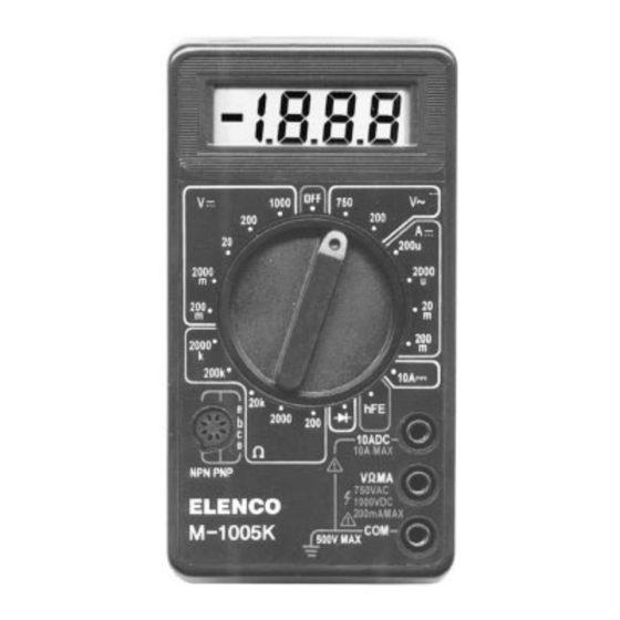
- Page 1 DIGITAL MULTIMETER KIT MODEL M-1005K Assembly and Instruction Manual Elenco Electronics, Inc. Copyright © 1996 Elenco Electronics, Inc. REV-J Revised 2000 753042...
-
Page 2: Parts List
PARTS LIST Contact Elenco Electronics (address/phone/e-mail is at the back of this manual) if any parts are missing or damaged. DO NOT contact your place of purchase as they will not be able to help you. SYMBOL R10, R* R16, R26... -
Page 3: Parts Identification
PARTS IDENTIFICATION Resistors Shunt Wire Ball Springs Potentiometer Bearing Selector Knob Transistor IDENTIFYING RESISTOR VALUES Use the following information as a guide in properly identifying the value of resistors. BAND 1 BAND 2 1st Digit 2nd Digit Color Digit Color Black Black Brown... - Page 4 Introduction Assembly of your M-1005K Digital Multimeter Kit will prove to be an exciting project and give you much satisfaction and personal achievement. If you have experience in soldering and wiring techniques, then you should have no problem with the assembly of this kit.
- Page 5 ASSEMBLY INSTRUCTIONS Identify and install the following parts as shown in Figure 4-1. After soldering each part, mark a check in the box provided. Be sure that solder has not bridged to an adjacent pad. C3 - .1 F (104) Mylar Small C2 - .1 F (104) Mylar Small VR1 - 200 (201) Potentiometer (see Figure A)
- Page 6 ASSEMBLY INSTRUCTIONS Identify and install the following parts as shown in Figure 4-2. After soldering each part, mark a check in the box provided. Be sure that solder has not bridged to an adjacent pad. IC - Socket 40-pin IC - 7106 (see Figure D) R11 - 9k 1% 1/4W Resistor (white-black-black-brown-brown)
- Page 7 Install the following parts. Then, place a check mark in the box provided. Spring Solder the 1/2 inch spring to the PC board as shown in Figure 4-3. This spring will contact the metal shield on the case bottom when the bottom is installed.
- Page 8 Remove the clear protective film from the front of the LCD (Note: Clear Protective Film DO NOT remove the silver backing). Place the LCD and zebras in the LCD frame as shown in Figure 4-5. Be sure that the LCD tab is in the same direction as shown in the figure.
- Page 9 Figure 4-7 Close-up View TESTING, CALIBRATION, AND TROUBLESHOOTING TESTING OF LCD With no test leads connected to the meter, move the selector switch around the dial. You should obtain the following readings. A (--) sign may also be present or blinking. 1) DCV Range: 200m 2000m...
-
Page 10: A/D Converter Calibration
If any of these tests fail: a) Check that the battery is good. b) Check that IC1 is installed according to Figure 4-2 of the assembly instructions. Check for bent pins that do not extend into the IC socket. Check for good contact between the leads of the IC and the pins of the socket. c) Check the values of resistors R14, R15, R19, R20, R23 - R25. - Page 11 AC VOLTS TEST To test the ACV ranges, we will need a source of AC voltage. The AC power line is the most convenient. CAUTION: Be very careful when working with 120VAC. Be sure that the range switch is in the 200 or 750VAC position before connecting the test leads to 120VAC.
-
Page 12: Final Assembly
Battery THEORY OF OPERATION A block diagram of the M-1005K is shown in Figure 7-1. Operation centers around a custom LSI chip. This chip contains a dual slope A/D (analog to digital) converter, display latches, seven segment decoder and display drivers. - Page 13 For resistance measurements, an internal voltage source drives the test resistor in series with a known resistor. The ratio of the test resistor voltage to the known resistor voltage is used to determine the value of the test resistor. The input of the 7106 IC is fed to an A/D converter. Here the DC voltage is changed to a digital format. The resulting signals are processed in the decoders to light the appropriate LCD segments.
-
Page 14: Digital Section
TYPICAL SEGMENT OUTPUT 0.5mA Segment Internal Digital Ground Figure 7-2 7106 IC Functions * Three inverters. One inverter shown for clarity. REF HI 10 A IN HI COMMON IN LO Figure 7-3 LCD PHASE DRIVER 7 Segment Decode Output Thousand Hundreds To Switch Drivers From Comparator Output... -
Page 15: Dc Voltage Measurement
DC VOLTAGE MEASUREMENT Figure 7-4 shows a simplified diagram of the DC voltage measurement function. The input voltage divider resistors add up to 1 megaohm. Each step down divides the voltage by a factor of ten. The divider output must be within the range -0.199 to +0.199 volts or the overload indicator will function. -
Page 16: Resistance Measurement
RESISTANCE MEASUREMENT Figure 7-7 shows a simplified diagram of the resistance measurement function. A simple series circuit is formed by the voltage source, a reference resistor from the voltage divider (selected by the selector switches), and the test (unknown) resistor. The ratio of the two resistors is equal to the ratio of their respective voltage drops. -
Page 17: Meter Operation
METER OPERATION PRECAUTIONS AND PREPARATIONS FOR MEASUREMENT 1) Be sure the battery is connected to the battery snap and correctly placed in the battery compartment. 2) Before connecting the test leads to the circuit, be sure the range switch is set to the correct position. 3) Be sure that the test leads are connected to the correct meter terminals before connecting them to the circuit. -
Page 18: Resistance Measurements
8. A resistor with the band colors green-black-green-brown-green is . . . A) 50.5k B) 5.15k C) 5.05k D) 5.05k 9. The M-1005K has . . . A) A 3 digit display. B) A 3 1/2 digit display. C) A 4 1/2 digit display. D) None of the above. -
Page 19: Schematic Diagram
SCHEMATIC DIAGRAM -18-... - Page 20 Elenco Electronics, Inc. 150 W. Carpenter Avenue Wheeling, IL 60090 (847) 541-3800 www.elenco.com e-mail: elenco@elenco.com...