Perkins 1103 Series Workshop Manual
Hide thumbs
Also See for 1103 Series:
- Disassembly and assembly (136 pages) ,
- Operation and maintenance manual (92 pages) ,
- Operation and maintenance manual (85 pages)
Table of Contents
Advertisement
Perkins 1103 &1104 Series
Perkins 1103 &1104 Series
WORKSHOP MANUAL
WORKSHOP MANUAL
S S ys
ystems Ope
tems Operatio
ration /
n /
T T e e sti
sting and Ad
ng and Adjus
justi ting
ng
3 a
3 and
nd 4 cylin
4 cylinder
der, na
, natur
tura a lly
lly a a spi
spirate
rated, a
d, and
nd tur
turboc
bocharged
harged
diese
diesel engines for agricult
l engines for agricult ural a
ural and i
nd i ndustr
ndustr ial use
ial use
Publication SENR9777-00
Publication SENR9777-00
© Proprietary information of Perkins Engines Company Limited 2004, all rights reserved.
© Proprietary information of Perkins Engines Company Limited 2004, all rights reserved.
The information is correct at the time of print.
The information is correct at the time of print.
Published by
Published by T T echnical Publications.
echnical Publications.
Perkins Engines Company Limited, Peterborough, PE1 5NA, England
Perkins Engines Company Limited, Peterborough, PE1 5NA, England
Advertisement
Table of Contents

Related Manuals for Perkins 1103 Series


Summary of Contents for Perkins 1103 Series
- Page 1 Publication SENR9777-00 Publication SENR9777-00 © Proprietary information of Perkins Engines Company Limited 2004, all rights reserved. © Proprietary information of Perkins Engines Company Limited 2004, all rights reserved. The information is correct at the time of print. The information is correct at the time of print.
- Page 2 If a tool, procedure, work method or operating technique that is not specifically recommended by Perkins is used, work method or operating technique that is not specifically recommended by Perkins is used, you must satisfy yourself that it is safe you must satisfy yourself that it is safe for you and for others.
- Page 3 If a tool, procedure, work method or operating technique that is not specifically recommended by Perkins is used, work method or operating technique that is not specifically recommended by Perkins is used, you must satisfy yourself that it is safe you must satisfy yourself that it is safe for you and for others.
-
Page 4: Table Of Contents
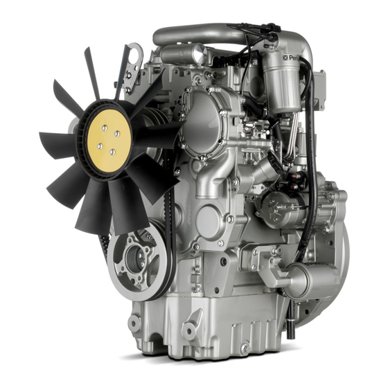
T T able of able of Contents Contents Table of Contents Table of Contents Electric Starting System - Test ......49 Electric Starting System - Test ......49 Glow Plugs Glow Plugs - Test ....- Test ................. - Page 5 Systems Operation Section Systems Operation Section Systems Operation Section Systems Operation Section i01958113 i01958113 Engine Design Engine Design g01014247 g01014247 Illustration 2 Illustration 2 1103 example of the layout of the valves 1103 example of the layout of the valves (A) Inlet valve (A) Inlet valve (B) Exhaust valve...
- Page 6 Systems Operation Section Systems Operation Section Coolant from the bottom of the radiator passes Coolant from the bottom of the radiator passes i01958097 i01958097 through the water pump. The water pump is driven through the water pump. The water pump is driven General General Informati Information...
- Page 7 Systems Operation Section 1104 Engine Model Views g00993373 Illustration 3 (1) Water temperature regulator housing (4) Engine oil cooler (7) Crankshaft pulley (2) Valve mechanism cover (5) Fan drive (8) Oil pan (3) Fuel transfer pump and fuel filter (6) Water pump (9) Engine oil filter...
- Page 8 Systems Operation Section g00928546 Illustration 4 (10) Engine oil filler cap (13) Alternator (16) Starter motor (11) Exhaust manifold (14) Flywheel housing (12) Turbocharger (15) Flywheel...
- Page 9 Systems Operation Section 1103 Engine Model Views g01011348 Illustration 5 (1) Alternator (3) Turbocharger oil supply (5) Turbocharger (2) Fan pulley (4) Turbocharger oil drain (6) Exhaust manifold...
-
Page 10: Fuel System Fuel System
Systems Operation Section g01011349 Illustration 6 (1) Fuel transfer pump (6) Oil filter (2) Oil filler cap (7) Oil pan (3) Fuel filter (8) Crankshaft pulley (4) Starter motor (9) Water pump (5) Dipstick (10) Water temperature regulator housing The fuel transfer pump draws fuel from the fuel i01912946 tank and through the water separator. - Page 11 The Delphi DP210 fuel injection pump must be serviced by an authorized Delphi technician. For repair information, contact your Perkins dealer or contact your Perkins distributor. High idle and low idle of the fuel injection pump are factory set.
- Page 12 Systems Operation Section Engines which are naturally aspirated pull outside • Power output is increased. air through an air cleaner directly into the inlet manifold (2). The air flows from the intake manifold • Fuel efficiency is increased. to the engine cylinders (3). The fuel is mixed with the air in the engine cylinders.
- Page 13 Systems Operation Section The oil from the main gallery of the cylinder block The camshaft gear is driven by the crankshaft gear. flows through the oil inlet port (5) in order to The camshaft and the crankshaft are timed together. lubricate the turbocharger bearings (4) and (6).
- Page 14 Systems Operation Section i01958103 Lubrication System g01009682 Illustration 9 Flow diagram of the lubrication system for the 1104 engine...
- Page 15 Systems Operation Section g01016473 Illustration 10 Flow diagram of the lubrication system for the 1103 engine Pressure for the lubrication system is supplied by Lubricating oil from the oil pan flows through a the oil pump (10). The crankshaft gear (13) drives strainer and a pipe (9) to the suction side of the a lower idler gear (12).
- Page 16 Systems Operation Section The oil flows from the oil filter through a passage that is drilled across the cylinder block to the oil gallery (4). The oil gallery is drilled through the total length of the left side of the cylinder block. If the oil filter is on the right side of the engine, the oil flows through a passage that is drilled across the cylinder block to the pressure gallery.
- Page 17 Systems Operation Section i01958111 Cooling System g00985481 Illustration 11 Flow diagram of the cooling system for the 1104 engine...
-
Page 18: Basic Engine Basic Engine
Systems Operation Section g01016432 Illustration 12 Flow diagram of the cooling system for the 1103 engine The coolant flows from the bottom of the radiator to The coolant flows forward through the cylinder head the centrifugal water pump. The water pump assists and into the water temperature regulator housing. - Page 19 Systems Operation Section The cylinder block for the 1104 engine has five The connecting rod is matched to each cylinder. main bearings which support the crankshaft. Thrust The piston height is controlled by the length of the washers on both sides of the center main bearing connecting rod.
- Page 20 Systems Operation Section i01958096 Electrical System The electrical system is a negative ground system. The charging circuit operates when the engine is running. The alternator in the charging circuit produces direct current for the electrical system. Starting Motor g00954820 Illustration 13 12 Volt Starting Motor (1) Terminal for connection of the battery cable (2) Terminal for connection of the ignition switch...
- Page 21 Systems Operation Section g00956095 Illustration 14 24 Volt Starting Motor (1) Terminal for connection of the ignition (2) Terminal for connection of the battery switch cable Alternator The starting motor turns the engine flywheel. The rpm must be high enough in order to initiate a sustained operation of the fuel ignition in the cylinders.
- Page 22 Systems Operation Section The alternator is an electro-mechanical component. The alternator is driven by a belt from the crankshaft pulley. The alternator charges the storage battery during the engine operation. The alternator converts the mechanical energy and the magnetic energy into alternating current and voltage.
-
Page 23: Fuel System - Inspect
Testing and Adjusting Section Testing and Adjusting 2. Install a suitable fuel flow tube with a visual sight gauge in the fuel return line. When possible, Section install the sight gauge in a straight section of the fuel line that is at least 304.8 mm (12 inches) long. -
Page 24: Finding Top Center Position For No. 1 Piston
Testing and Adjusting Section 3. If excessive air is seen in the sight gauge in the i01893344 fuel return line, install a second sight gauge at Finding Top Center Position the inlet to the fuel transfer pump. If a second for No. -
Page 25: Fuel Injection Pump Timing - Check
Pump Note: The Delphi DP210 Series fuel injection pump timing cannot be checked. If you suspect that the fuel injection pump timing is incorrect, contact your Perkins dealer or your Perkins distributor for further g00988405 Illustration 18 information. (1) Plug The Delphi DP210 Series fuel injection pump must be serviced by an authorized Delphi technician. -
Page 26: Fuel Injection Pump Timing - Adjust
The Delphi DP210 Series fuel injection pump must be serviced by an authorized Delphi technician. For repair information, contact your Perkins dealer or your Perkins distributor. The internal adjustment for the pump timing is tamper proof. High idle and low idle of the fuel injection pump are factory set. - Page 27 Testing and Adjusting Section 4. Remove the plug (1) and the washer from 11. Remove the fuel injection pump gear. Refer the rear of the fuel injection pump and install to Disassembly and Assembly, “ Fuel Injection fuel injection pump timing adapter (2). pump - Remove 27610248 ”...
-
Page 28: Fuel Quality - Fuel Quality - T T Est Est
Testing and Adjusting Section 14. Install the front cover. Refer to Disassembly and • Cetane number of the fuel Assembly, “ Front Cover - Remove and Install ” • Air in the fuel 15. Install the water pump. Refer to Disassembly and Assembly, “... -
Page 29: Fuel System Pressure - Test
Testing and Adjusting Section Check the Function of the Pressure i01944991 Regulator Fuel System Pressure - Test 1. Remove the fuel line from the outlet for the supply for the fuel injection pump (B). 2. Install a pipe with a tap for a pressure gauge. Connect a 0 to 80 kPa (0 to 12 psi) pressure gauge. -
Page 30: Air Inlet And Exhaust System
3. Carefully apply the air pressure until the air pressure has moved the rod 1 mm (0.0394 inch). Check that the air pressure is correct for your turbocharger. 4. For more information on installing a new turbocharger, contact your Perkins dealer or your Perkins distributor. -
Page 31: Compression - T T Est Compression - Est
Testing and Adjusting Section Refer to Systems Operation, “ Engine Design ” i01888954 the location of the cylinder valves. Compression - Test If the valve lash requires adjustment several times in a short period of time, excessive wear exists in a different part of the engine. - Page 32 Testing and Adjusting Section Table 4 Inlet Valves Exhaust Valves 1104 1104 Accidental engine starting can cause injury or death to personnel. Valve Lash 0.20 mm 0.45 mm (Stopped (0.008 inch) (0.018 inch) To prevent accidental engine starting, turn the ig- Engine) nition switch to the OFF position, place a do not operate tag at the ignition switch location and dis-...
- Page 33 Testing and Adjusting Section Table 7 TC Exhaust Inlet Valves Exhaust Valve Stroke (3 ) 0.20 mm 0.45 mm Valve Lash (0.008 inch) (0.018 inch) Cylinders Position for No. 1 cylinder 4. Adjust the valves according to Table 7. a. Lightly tap the rocker arm at the top of the adjustment screw with a soft mallet.
-
Page 34: Inspect
Testing and Adjusting Section d. Place the correct feeler gauge between the rocker arm and the valve stem. Then, turn the adjustment screw in a clockwise direction. Slide the feeler gauge between the rocker arm and the valve stem. Continue turning the adjustment screw until a slight drag is felt on the feeler gauge. - Page 35 Testing and Adjusting Section Refer to Specifications, “ Cylinder Head Valves ” for the maximum clearance of the valve in the valve guide. g00986821 Illustration 30 (1) Valve guide (2) Radial movement of the valve in the valve guide (3) Valve stem (4) Dial indicator (5) Valve head 1.
-
Page 36: Lubrication System
Testing and Adjusting Section Lubrication System i01893791 Engine Oil Pump - Inspect i01854908 Engine Oil Pressure - Test If any part of the oil pump is worn enough in order to affect the performance of the oil pump, the oil pump must be replaced. -
Page 37: Excessive Bearing Wear - Inspect
Testing and Adjusting Section i01126690 Excessive Bearing Wear - Inspect When some components of the engine show bearing wear in a short time, the cause can be a restriction in an oil passage. An engine oil pressure indicator may show that there is enough oil pressure, but a component is worn due to a lack of lubrication. -
Page 38: Increased Engine Oil T Increased Engine Oil Temperature - Inspect Emperature - Inspect
Testing and Adjusting Section • Leaks past the seal rings in the turbocharger shaft • Overfilling of the crankcase • Wrong dipstick or guide tube • Sustained operation at light loads Excessive consumption of engine oil can also result if engine oil with the wrong viscosity is used. Engine oil with a thin viscosity can be caused by fuel leakage into the crankcase or by increased engine temperature. -
Page 39: Cooling System
Testing and Adjusting Section Cooling System 6. Check the filler cap. A pressure drop in the cooling system can cause the boiling point to be lower. This can cause the cooling system to boil. Refer to Testing and Adjusting, “ Cooling System i01892576 - Test... -
Page 40: Cooling System - Inspect
Testing and Adjusting Section 13. When a load that is applied to the engine is too i01876572 large, the engine rpm does not increase with an Cooling System - Test increase of fuel. This lower engine rpm causes a reduction in coolant flow through the system. This combination of less air and less coolant flow during high input of fuel will cause above normal Remember that temperature and pressure work... - Page 41 Testing and Adjusting Section Making the Correct Antifreeze 1. After the engine cools, carefully loosen the filler cap. Slowly release the pressure from the cooling Mixtures system. Then, remove the filler cap. Do not add pure 21825166 POWERPART antifreeze 2.
-
Page 42: Engine Oil Cooler - Inspect
Testing and Adjusting Section 2. Make sure that the coolant covers the top of the radiator core. Personal injury can result from air pressure. 3. Put a suitable pressurizing Pump onto the radiator. Personal injury can result without following prop- er procedure. -
Page 43: Water Temperature Regulator - Test
Testing and Adjusting Section 4. Keep the water at the correct temperature for ten minutes. Personal injury can result from air pressure. 5. After ten minutes, remove the water temperature regulator housing. Immediately measure the Personal injury can result without following prop- opening of the water temperature regulator. -
Page 44: Basic Engine
Testing and Adjusting Section Basic Engine Inspect the Piston Ring End Gap i01889476 Piston Ring Groove - Inspect Inspect the Piston and the Piston Rings 1. Check the piston for wear and other damage. 2. Check that the piston rings are free to move in the grooves and that the rings are not broken. -
Page 45: Connecting Rod Bearings - Inspect
Testing and Adjusting Section i01748770 Connecting Rod Bearings - Inspect Check the connecting rod bearings and the connecting rod bearing journal for wear or other damage. Connecting rod bearings are available with a smaller inside diameter than the original size bearings. -
Page 46: Cylinder Head - Inspect
Testing and Adjusting Section Refer to Specifications, “ Cylinder Head ” for the i01905914 requirements of flatness. Cylinder Head - Inspect Remachining the Cylinder Head The bottom face of cylinder head can be resurfaced 1. Remove the cylinder head from the engine. if any of the following conditions exist: 2. -
Page 47: Flywheel - Inspect Flywheel - Inspect
Testing and Adjusting Section The correct piston height must be maintained in i01897548 order to ensure that the engine conforms to the Flywheel - Inspect standards for emissions. Note: The top of the piston should not be machined. If the original piston is installed, be sure that Alignment of the Flywheel Face the original piston is assembled to the correct connecting rod and installed in the original cylinder. -
Page 48: Gear Group - Inspect
Testing and Adjusting Section Flywheel Runout i01958093 Gear Group - Inspect g00987752 Illustration 42 1. Install the dial indicator. Refer to Illustration 42. g00918708 Illustration 43 2. Set the pointer of the dial indicator to 0 mm (1) Fuel pump drive gear (0 inch). -
Page 49: Electrical System
Testing and Adjusting Section Electrical System 4. Turn the ignition switch to the ON position. Check the voltage between terminal (B) and ground. If the voltage is more than 2 Volts the alternator needs to be replaced. i01899123 Alternator - Test Warning Light is On When the Engine is Running 1. -
Page 50: Electric Starting System - Test
Testing and Adjusting Section The starting motor solenoid has two coils. The pull-in coil draws about 40 amperes. The hold-in coil requires about 5 amperes. Never disconnect any charging unit circuit or bat- tery circuit cable from the battery when the charg- When the magnetic force increases in both coils, ing unit is operated. - Page 51 Testing and Adjusting Section Voltage drops that are greater than the amounts in Note: If the following conditions exist, do not Table 12 are caused most often by the following perform the test in Step 2 because the starting conditions: motor has a problem.
-
Page 52: Test
Testing and Adjusting Section c. The voltage drops are greater than the voltage 1. Disconnect the power supply and the bus bar. drops that are given in Table 12. The faulty component should be repaired or replaced. 2. Connect the power supply to only one glow plug. 5. -
Page 53: V-Belt - - T T Est V-Belt Est
Testing and Adjusting Section i01955101 V-Belt - Test Table 15 Belt Tension Chart Gauge Reading Size of Belt Width of Belt Initial Belt Tension (1 ) Used Belt Tension (2 ) 13.89 mm (0.547 Inch) 535 N (120 lb) 355 N (80 lb) Measure the tension of the belt that is farthest from the engine. -
Page 54: Index
Index Section Index Engine Valve Lash - Inspect/Adjust ....... 30 Inspect Valve Lash ..........30 Air in Fuel - Test............. 22 Valve Lash Adjustment for the 1103 engine..32 Air Inlet and Exhaust System ......10, 29 Valve Lash Adjustment for the 1104 engine..31 Cylinder Head And Valves .........