
Related Manuals for Siemens 3AF 01


Summary of Contents for Siemens 3AF 01
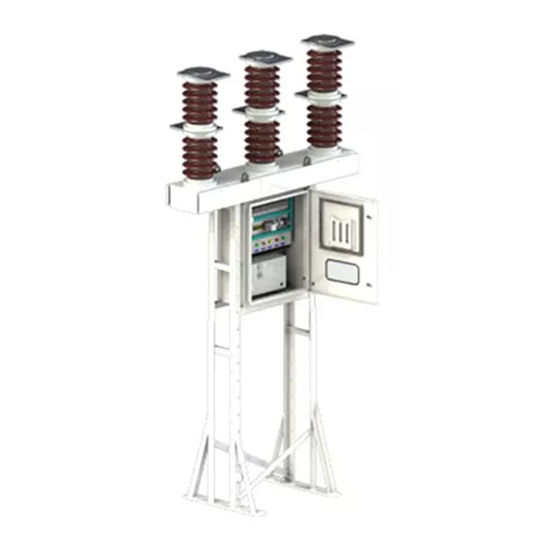
- Page 1 3AF 01 Outdoor Vacuum Switchgear 36 kV Operating Instructions Manual 4P-0080-03-95273-001AB...
-
Page 2: Table Of Contents
Is trained and authorized to energize, de-energize, clear, ground and tag circuits and purchased have been equipment in accordance with established safety practices. replaced by Siemens • Is trained in the proper care and use of protective equipment in accordance with personnel trained and established and safety practices. -
Page 3: General
(transport, storage), installation, operation and maintenance. 1. General NOTE Siemens 3AF 01 vacuum circuit-breakers are of the triple- pole outdoor type for rated voltage of 36 kV. In their basic design and with all standard listed equipment options, 3AF 01 vacuum circuit-breakers The vacuum circuit-breaker consists of a steel structure, a are type-tested components in accordance with IEC. -
Page 4: Technical Data
In the event of any queries, state the type designation, 2.1.1 Type designation design code, year of manufacture and the serial 3AF 01 vacuum circuit-breakers are identified by a number. machine-readable product designation made up of a series of numbers and letters, whose first 8 places can be 2.1.3... -
Page 5: Influence Of Environmental Parameters
For a specified rated withstand voltage of 185kV at an altitude of 1400m, an insulation level of at least 195kV The 3AF 01 vacuum circuit-breakers are designed for the under standard reference atmosphere is required: normal operating conditions laid down in the standards. -
Page 6: Load Current
40°C. The assemblies. maximum permissible load current as a function of the ambient temperature of the 3AF 01 circuit-breaker has When ordering replacement pole assemblies, state the been plotted in Fig. 4. circuit-breaker type, design code and serial number (see name plate). -
Page 7: Description
OFF button (P-6, Fig. 11). In the case of an electrical command being given, the tripping The vacuum interrupters fitted in the 3AF 01 vacuum solenoid Y1 (P-5, Fig. 11) unlatches the tripping spring. circuit-breakers are type-approved in accordance with the The opening sequence is similar to the closing sequence. - Page 8 1. Interrupter assembly 17. Vacuum interrupter SIDE VIEW 2. Base frame 18. Insulator 3. Steel structure 19. Contact pressure 5. Switching shaft spring 6. Insulating stud 20. Drive shaft 7. Handle (for slow 23. Bearing closing) 24. Operating mechanism 8. Lever 27.
-
Page 9: Equipment
4. Equipment part of the short spring charging time, the motors operate in the overload range. The basic version of the 3AF 01 vacuum circuit-breaker comprises: The supply voltage of the motor-operated mechanism may deviate from the rated value by -15% to +10%. -
Page 10: (Optional Feature)
unlatching mechanism is released and opening of the 4.3.6 Current transformer-operated release (Y4) circuit-breaker is thus initiated via the stored-energy 3AX1102 (optional feature) mechanism. The stored energy mechanism is Current transformer-operated (CT-operated) releases automatically recharged by the circuit-breaker. consist of a stored-energy mechanism, an unlatching The deliberate tripping of the undervoltage release mechanism and an electromagnet system. -
Page 11: Transport
Packing Cases is unpacked, take care that it is stored in a dry room The 3AF 01 outdoor vacuum circuit-breakers are and repack it if necessary. It is important that the despatched in one wooden case or in corrugated board. -
Page 12: Installation
Non-compliance can lead to damage. 12. Lock washer 13. Glass window for viewing mechanical indications The 3AF 01 outdoor vacuum circuit-breaker is 14. Operating mechanism housing despatched in one crate. The equipment is protected by polyethylene sheet while packing. The packing case is marked with the breaker serial number. -
Page 13: Electrical Connection
Any locking washer or gasket loosened or (iii) Cleaning exposed during assembly must be replaced. WARNING The following sequence should be followed : In line with the foundation plan shown in the G.A. drg., the foundation pockets are made. For safety reasons, cleaning may be taken up only Grout the foundation bolts and cure. -
Page 14: Commissioning
7. Commissioning Slow Opening Operation (Optional) Starting with the condition at the end of the slow closing operation Danger Insert the manual handle in the same position. Move the handle down still further. Keeping the handle pressed down, press the OFF High voltage! P.B. -
Page 15: Closing
Inert Gas in the Sealed Pole (optional feature) Inert gas N is filled up in each pole at about 1.5 bar during manufacturing, in order to prevent the entry and subsequent condensation of moisture during the service life of the breaker. The gas is not for the purpose of insulation. -
Page 16: Maintenance
Non-observance can result in death, severe personal injury or substantial damage to property. The 3AF 01 vacuum circuit-breakers in general require little maintenance. The interval at which the maintenance is to be carried out depends on the application by the client. The parameters to be considered are : —... -
Page 17: Checking The Contact Erosion
Checking of Contact Erosion The contact erosion is to be checked with the circuit- DANGER breaker in the ON condition. Carry out steps 1 to 5 as in clause 7.3 and close the breaker slowly as per clause 6.1. Non-observance can result in personal injury. Open the rear cover. - Page 18 Standard Spares for 36/40.5 kV V.C.B. (3AF01) M L F B No. Item No. 1. (Y1/Y3/Y9) : Closing or Tripping Release (consumption 200W / VA) a) 24V DC 3AY1510 - 3BY 4398095020 b) 30V DC 3AY1510 - 3MY 4398095021 c) 110V DC 3AY1510 - 3EY 4398095024 d) 220V DC...
-
Page 19: Service Life
PVC is used as an insulation material for control wire. Local customer support-Siemens office will be able to In as-supplied condition, the product does not answer any questions concerning disposal. -
Page 20: Troubleshooting
8.13 Troubleshooting Problem Symptoms / Effect Possible Causes / Reasons Remedial Measures Breaker 1. Closing spring charges, 1. Electrical power to auxiliary 1. Check electrical power to auxiliary fails to but breaker does not circuit is off, or MCB has tripped. circuit and/or replace blown fuses. -
Page 21: Typical Wiring Diagram
Note: MCBs are replaced by fuses and neutral links, if ordered. Service You can find your contact at the Siemens Regional Offices in your area and other Siemens addreses via the Thank you for placing your trust in us as a manufacturer internet under http://www.siemens.com of medium-voltage switchgear and components - and thus in our technology as a whole. - Page 22 Notes:...
- Page 23 Notes:...
- Page 24 Tel. : +91-22-2762 3544 Order No. 4P-0080-03-95273-001AB Fax : +91-22-2762 3715 Siemens Ltd. © 2010 Siemens Ltd. 'Product development is a continuous process. Consequently, the All rights reserved. data indicated in this Booklet is subject to change without prior PTD-03-118-0 Printed in India.