
Related Manuals for EverFocus ES2446-51


Summary of Contents for EverFocus ES2446-51
- Page 1 ES2446-51 24-port Gigabit PoE+ with 4 Combo SFP Rack-mount Web Smart PoE Switch User’s Manual Copyright © EverFocus Electronics Corp, Release Date: March, 2015 Notice: This content is subject to be changed without notice.
- Page 2 All rights reserved. No part of the contents of this manual may be reproduced or transmitted in any form or by any means without written permission of the Everfocus Electronics Corporation. Release Date: March, 2015 QuickTime is a registered trademark of the Apple Computer, Inc.
- Page 3 Safety Precautions FCC Warning This Equipment has been tested and found to comply with the limits for a Class-A digital device, pursuant to Part 15 of the FCC rules. These limits are designed to provide reasonable protection against harmful interference in a residential installation. This equipment generates, uses, and can radiate radio frequency energy.
-
Page 4: Table Of Contents
TABLE OF CONTENTS Introduction ........................1 1.1 Product Overview ......................1 1.2 General Features ......................1 1.3 Software Features ......................1 1.4 Package Contents ......................2 Hardware Description ....................3 2.1 Dimensions ........................3 2.2 Appearance & Front Panel ..................... 3 2.3 LED Indicators ........................ - Page 5 4.3.4 Configuration File Transfer ................34 4.3.5 Logout ....................... 34 4.4 Revision History ......................35 Specification ....................... 36...
-
Page 6: Introduction
ES2446-51 Chapter 1. Introduction 1.1 Product Overview The switch is 24-port 10/100/1000M PoE+ with 4 Combo SFP Rack-mount Web Smart PoE Switch, the switch supports IEEE 802.3at Power over Ethernet standard, maximum 400W power consumption per system. The switch also provides exceptionally smart Web management features, such as VLAN, QoS, RSTP, IGMP Snooping, LACP, IEEE 802.1X, Storm Control…etc. -
Page 7: Package Contents
ES2446-51 • Quality of Service: up to 4 queues, 802.1p • PoE Control: PoE Port Enabled/Disable, Status • IEEE 802.1X, Source IP Filter • Storm Control: Broadcast, Multicast, Flood Unicast • Port: Port State, Speed/Duplex, Flow Control • Rate Limiting, Port Mirroring •... -
Page 8: Hardware Description
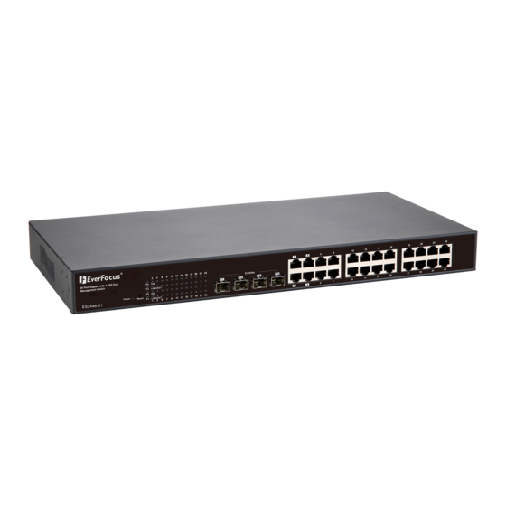
ES2446-51 Chapter 2. Hardware Description This part primarily presents hardware of the web-smart switch, physical dimension, appearance, front panel, rear panel and LED indicator. 2.1 Dimensions 44 × 440 × 331 mm (H × W × D)/4.7kg 2.2 Appearance & Front Panel The front Panel of the web-smart Switch consists of 24 gigabit RJ-45 ports, 4 of the gigabit RJ-45 ports (Port 1~4) combo with 4 gigabit SFP open slot. -
Page 9: Led Indicators
ES2446-51 Front Panel Note 1: The SFP ports are shared with normal RJ-45 ports 1,2,3 and 4. For example: The RJ-45 Port 1 can not be used when SFP Port 1 link up. Note 2: Click the Reset button for 5 seconds, the system configuration will be reset to default. -
Page 10: Hardware Installation
ES2446-51 2.5 Hardware Installation The switch is usually mounted in the 19” rack, the rack is usually installed in IT room or other secured place. The switch supports AC power input and rackmount mounting. Make sure all the power cables, Ethernet cables, screws and the air circulation are well prepared and installed as below description. -
Page 11: Preparation For Web Interface
ES2446-51 Chapter 3. Preparation for Web Interface The web management page allows you to use a standard web-browser such as Microsoft Internet Explorer, Google Chrome or Mozila Firefox, to configure and interrogate the switch from anywhere on the network. Before you attempt to use the web user interface to manage switch operation, verify that your Switch is properly installed on your network and that every PC on this network can access the switch via the web browser. - Page 12 ES2446-51 6. Launch the web browser (Internet Explorer or Mozila Firefox) on the PC. 7. Type http://192.168.2.1 (or the IP address of the switch). And then press Enter. 8. The login screen will appear next. 9. Key in the password. Default password is no password. Click “Apply” directly.
- Page 13 ES2446-51 Trouble Shooting If you can't login the switch, the following steps can help you to identify the problem. 1. Switch to DOS command mode and type the "ipconfig" to check the NIC's setting. Type the "ping 192.168.2.1" to verify a normal response time.
-
Page 14: Web Ui Configuration
ES2446-51 Chapter 4. Web UI Configuration This part instructs user how to set up and manage the switch through the web user interface. Please follow the description to understand the procedure. 4.1 Configuration This part shows how to configure the switch settings. - Page 15 ES2446-51 DHCP Server: The IP of the DHCP Server. Display after DHCP Client enabled. Lease Time Left: The least received from the DHCP server. Display after the DHCP Client enabled. DHCP Enabled: Click the box to enable DHCP Client mode.
-
Page 16: Ports
ES2446-51 1and 2c management clients. SNMP Trap Destination: IP address of the trap manager to receive notification messages from this switch. Traps indicating status changes are issued by the switch to specified trap managers. You must specify trap managers so that key events are reported by this switch to your management station. -
Page 17: Vlan
ES2446-51 4.1.3 VLAN A Virtual LAN (VLAN) is a logical network grouping that limits the broadcast domain, which would allow you to isolate network traffic, so only the members of the same VLAN will receive traffic from the ones of the same VLAN. Basically, creating a VLAN from a switch is logically equivalent of reconnecting a group of network devices to another Layer 2 switch. - Page 18 ES2446-51 VLAN ID: ID of configured VLAN (1-4094, no leading zeroes). Type the new ID and click Add. The web UI is directed to the VLAN Setup screen. VLAN Configuration List: Lists all the current VLAN groups created for this system.
-
Page 19: Aggregation
ES2446-51 4.1.4 Aggregation Port trunk allows multiple links to be bundled together and act as a single physical link for increased throughput. It provides load balancing, and redundancy of links in a switched inter-network. Actually, the link does not have an inherent total bandwidth equal to the sum of its component physical links. - Page 20 ES2446-51 LACP Port Configuration Port: The port ID. Protocol Enabled: Enables LACP Protocol on the associated port. Key Value: Configures a port's LACP administration key. The port administrative key must be set to the same value for ports that belong to the same link aggregation group (LAG).
-
Page 21: Rstp
ES2446-51 4.1.6 RSTP IEEE 802.1w Rapid Spanning tree protocol (LACP) provides a loop-free network and redundant links to the core network with rapid convergence to ensure faster recovery from failed links, enhancing overall network stability and reliability. RSTP System Configuration ... - Page 22 ES2446-51 Path Cost: This parameter is used by the STP to determine the best path between devices. Therefore, lower values should be assigned to ports attached to faster media, and higher values assigned to ports with slower media. Set the RSTP path cost on the port.
-
Page 23: 802.1X Configuration
ES2446-51 4.1.7 802.1X Configuration IEEE802.1X provides a security standard for network access control, especially in Wi-Fi wireless networks. 802.1X holds a network port disconnected until authentication is completed. The switch uses Extensible Autentication Protocol over LANS to exchange authentication protocol client identity with the client, and forward it to another remote RADIUS authentication server to verify access rights. -
Page 24: Igmp Snooping
ES2446-51 Admin State: There are 3 types, Auto, Force Authorized and Force Unauthorized. Auto: Select Auto when you enabled the IEEE 802.1X. If the client is successfully authorized, the port is authorized to be used as well. Otherwise, the port can’t be used. -
Page 25: Mirroring
ES2446-51 IGMP Configuration IGMP Enabled: When enabled, the switch will monitor network traffic to determine which hosts want to receive multicast traffic. Router Ports: Set if ports are connecting to the IGMP administrative routers. Unregistered IPMC Flooding enabled: Set the forwarding mode for unregistered (not-joined) IP multicast traffic. -
Page 26: Qos
ES2446-51 4.1.10 QoS In QoS Mode, select QoS Disabled, 802.1p, or DSCP to configure the related parameters. QoS Mode: QoS Disabled When the QoS Mode is set to QoS Disabled, the QoS is disabled. - Page 27 ES2446-51 QoS Mode: 802.1p Packets are prioritized using the 802.1p field in the VLAN tag. This field is three bits long, representing the values 0 - 7. When the QoS Mode is set to 802.1p, the 802.1p Configuration table appears, allowing you to map each of the eight 802.1p values to a local priority queue (low, normal, medium or high).
- Page 28 ES2446-51 Type the DSCP Value and Priority mapping in below screen. Queue Mode: Strict: Services the egress queues in sequential order, transmitting all traffic in the higher priority queues before servicing lower priority queues. WRR: Weighted Round-Robin shares bandwidth at the egress ports by using scheduling weights with default values of 1, 2, 4, 8 for queues 0 through 7, respectively.
-
Page 29: Filter Configuration
ES2446-51 4.1.11 Filter Configuration There are 3 mode that you can choose for filter configuration: Disabled: this mode is disabled, no any protection here. Static: The IP address you typed here can’t access the switch. DHCP: The IP address retrieve from the DHCP server can’t access the switch. -
Page 30: Rate Limit Configuration
ES2446-51 The green are shows the status of the connected PD. To protect the system and better product life, lower than 80% Power Budget is suggested. 4.1.13 Rate Limit Configuration Type of Port: You can define the certain port as Policer and Shaper before you set up the rate limit. -
Page 31: Storm Control
ES2446-51 4.1.14 Storm Control Broadcast storms may occur when a device on your network is malfunctioning, or if application programs are not well designed or properly configured. If there is too much broadcast traffic on your network, performance can be severely degraded or everything can come to complete halt. - Page 32 ES2446-51 Enable Rate Limit: Click the check box and the rate to enable storm control. Rate (number of frames per second): The Rate field is set by a single drop-down list. The same threshold is applied to every port on the switch. When the threshold is exceeded, packets are dropped, irrespective of the flow-control settings.
-
Page 33: Monitorning
ES2446-51 4.2 Monitorning 4.2.1 Statistic Overview Statistic Overview for all ports User can mirror traffic from any source port to a target port for real-time analysis the following figures shows clearly the statistics overview. 4.2.2 Detailed Statics To view the statistics of individual ports, click one of the linked port numbers for details. -
Page 34: Lacp Status
ES2446-51 4.2.3 LACP Status LACP Aggregation Overview LACP allows for the automatic detection of links in a Port Trunking Group Port: The port number. Port Active: Shows if the port is a member of an active LACP group. - Page 35 ES2446-51 Hello Time: Interval (in seconds) at which the root device transmits a configuration message. Max Age: The maximum time (in seconds) a device can wait without receiving a configuration message before attempting to reconfigure. All device ports (except for designated ports) should receive configuration messages at regular intervals.
-
Page 36: Igmp Status
ES2446-51 4.2.5 IGMP Status IGMP Status IGMP Status shows the IGMP Snooping statistics for the whole switch. VLAN ID: VLAN ID number. Querier: Show whether Querying is enabled. Queries transmitted: Show the number of transmitted Query packets. -
Page 37: Maintenance
ES2446-51 4.3 Maintenance 4.3.1 Warm Restart Press Yes button to restart the switch, the reset will be complete when the power lights stop blinking. 4.3.2 Factory Default Forces the switch to restore the original factory settings. To reset the switch, select “Reset to Factory Defaults”... -
Page 38: Software Upload
ES2446-51 If you forgot the password, you can press the Reset button on the front panel for 5 seconds. Then the system will be reset to default configuration. 4.3.3 Software upload Select “Upgrade Firmware” from the Tools drop-down list then click on the “Browse”... -
Page 39: Configuration File Transfer
ES2446-51 4.3.4 Configuration File Transfer Configuration file transfer allows you to save the switch’s current configuration or restore a previously saved configuration back to the device. Configuration files can be saved to any location on the web management station. To upload the configuration file to save a configuration or "Download"... -
Page 40: Revision History
ES2446-51 4.4 Revision History Edition Date Modifications Update the product information. V1.1 Jan. 31, 2013 Revise the Web GUI description of the features. Add revision history... -
Page 41: Specification
ES2446-51 Chapter Specification Model Name ES2446-51 Ethernet: IEEE 802.3 10BaseT, IEEE 802.3u 100BaseTX, IEEE 802.ab 1000BaseT, IEEE 802.3z 1000BaseSX/LX IEEE 802.3x Full-duplex and Flow Control IEEE 802.1Q VLAN IEEE 802.3ad Link Aggregation Control Protocol Standards IEEE 802.1D Spanning Tree Protocol IEEE 802.1w Rapid Spanning Tree Protocol... - Page 42 ES2446-51 1000Mbps port – 1,488,000pps Filtering/Forwarding 100Mbps port - 148,800pps, 10Mbps port - Rates 14,880pps 10BaseT Cat. 3, 4, 5 UTP/STP, 100BaseTX Cat. 5 UTP/STP Transmission Media 1000BaseT Cat. 5E UTP/STP Per Port: Link/Act; Per Unit: Power Led Indicators 100~240V/AC, 50~60Hz...
- Page 43 TEL: +91 22 6726 4500 FAX: +91 22 6726 4518 www.everfocus.in sales@everfocus.in Ihr EverFocus Produkt wurde entwickelt Your EverFocus product is designed and und hergestellt mit qualitativ manufactured with high quality materials hochwertigen Materialien und and components which can be recycled Komponenten, die recycelt und wieder and reused.