Table of Contents
Advertisement
Quick Links
Advertisement
Table of Contents

Related Manuals for Asus RS100-E10-PI2


Summary of Contents for Asus RS100-E10-PI2
- Page 1 RS100-E10-PI2 1U Rackmount Server User Guide...
- Page 2 ASUSTeK COMPUTER INC. (“ASUS”). ASUS provides this manual “as is” without warranty of any kind, either express or implied, including but not limited to the implied warranties or conditions of merchantability or fitness for a particular purpose. In no...
-
Page 3: Table Of Contents
Contents Safety information ..................... vii About this guide ......................ix Chapter 1: Product Introduction System package contents ................. 1-2 Serial number label ..................1-2 System specifications ................1-3 Front panel features ................... 1-5 Rear panel features ..................1-5 Internal features ..................1-6 LED information .................. - Page 4 Q-Code table ................4-17 4.5.3 Internal connectors..............4-19 Chapter 5: BIOS Setup Managing and updating your BIOS ............5-2 5.1.1 ASUS CrashFree BIOS 3 utility........... 5-2 5.1.2 ASUS EzFlash Utility..............5-3 5.1.3 BUPDATER utility ............... 5-4 BIOS setup program .................. 5-6 5.2.1...
- Page 5 Contents Main menu ....................5-9 Performance Tuning menu ..............5-10 Advanced menu ..................5-11 5.5.1 CPU Configuration ..............5-12 5.5.2 Power & Performance ............... 5-14 5.5.3 Server ME Configuration ............5-16 5.5.4 Trusted Computing..............5-16 5.5.5 APM Configuration ..............5-17 5.5.6 Runtime Error Logging Settings ..........
- Page 6 7.1.2 Installing the RAID controller driver..........7-2 Management applications and utilities installation ........ 7-5 Running the Support DVD ................. 7-5 Installing the system drivers ..............7-6 Appendix P11C-M/4L block diagram ..................A-2 Notices ........................A-3 ASUS contact information ..................A-6...
-
Page 7: Safety Information
Safety information Electrical Safety • Before installing or removing signal cables, ensure that the power cables for the system unit and all attached devices are unplugged. • To prevent electrical shock hazard, disconnect the power cable from the electrical outlet before relocating the system. - Page 8 Lithium-Ion Battery Warning CAUTION! Danger of explosion if battery is incorrectly replaced. Replace only with the same or equivalent type recommended by the manufacturer. Dispose of used batteries according to the manufacturer’s instructions. Heavy System CAUTION! This server system is heavy. Ask for assistance when moving or carrying the system.
-
Page 9: About This Guide
About this guide Audience This user guide is intended for system integrators, and experienced users with at least basic knowledge of configuring a server. Contents This guide contains the following parts: Chapter 1: Product Introduction This chapter describes the general features of the server, including sections on front panel and rear panel specifications. - Page 10 Refer to the following sources for additional information, and for product and software updates. ASUS Control Center (ACC) user guide This manual tells how to set up and use the proprietary ASUS server management utility. ASUS websites The ASUS websites worldwide provide updated information for all ASUS hardware and...
-
Page 11: Chapter 1: Product Introduction
Chapter 1: Product Introduction Product Introduction This chapter describes the general features of the server, including sections on front panel and rear panel specifications. -
Page 12: System Package Contents
If any of the above items is damaged or missing, contact your retailer. Serial number label Before requesting support from the ASUS Technical Support team, take note of the product’s 12-character serial number as seen in the example xxS0xxxxxxxx below. With the correct serial number of the product, ASUS Technical Support team members can quickly identify the server model and provide a satisfactory solution to your technical issue. -
Page 13: System Specifications
System specifications The ASUS RS100-E10-PI2 is a 1U barebone server system featuring the ASUS P11C-M/4L server board. Model Name RS100-E10-PI2 1 x Socket LGA1151 ® ® Processor / System Bus Intel Xeon processor E-21xx / E-22xx product family (95W) ®... - Page 14 1 x Location switch/LED 1 x Reset switch 1 x HDD Access LED 1 x Message LED LAN 1-4 LED OS Support Please find the latest OS support from http://www.asus.com Out of Band Management Remote Optional ASMB9-iKVM for KVM-over-IP Hardware...
-
Page 15: Front Panel Features
LAN port 3-4 AC power socket LAN port 1-2 Q-Code USB 3.1 Gen 1 ports USB 3.1 Gen 2 ports Q-Code LED VGA port Power button Location LED Message LED *This port is for an ASUS ASMB9-iKVM controller card only. ASUS RS100-E10-PI2... -
Page 16: Internal Features
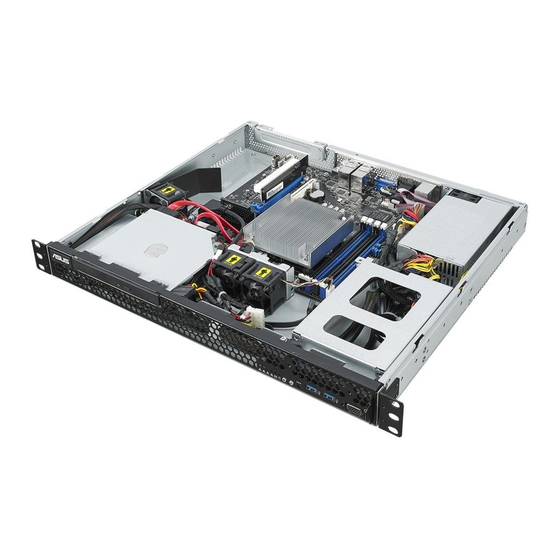
Internal features The barebone server includes the basic components as shown. PCI-E Gen3 x16 Slot with Riser Card (at x8 link) System Fan ASUS P11C-M/4L Server board Power Supply Slim-type Optical Drive (Optional) HDD Bay 2 HDD Bay 1 (partly hidden) Turn off the system power and detach the power supply before removing or replacing any system component. -
Page 17: Led Information
A hardware monitor event is indicated Normal status Location LED Location switch is pressed (Press the location switch again to turn off) No LAN connection Blinking LAN LEDs LAN is transmitting or receiving data LAN connection is present ASUS RS100-E10-PI2... -
Page 18: Rear Panel Leds
1.7.2 Rear panel LEDs Q-Code Location LED Message LED Icon Display status Description Normal status Location LED Location switch is pressed (Press the location switch again to turn off) System is normal; no incoming event Message LED A hardware monitor event is indicated 1.7.3 LAN (RJ-45) LEDs LAN port LED indications... -
Page 19: Chapter 2: Hardware Information
Chapter 2: Hardware Information Hardware Information This chapter lists the hardware setup procedures that you have to perform when installing or removing system components. -
Page 20: Chassis Cover
Chassis cover 2.1.1 Removing the chassis cover • Unplug the power cord before removing the chassis cover. • Take extra care when removing the chassis cover. Keep your fingers away from components inside the chassis that can cause injury, such as the CPU fan, rear fan, and parts with sharp or protruding edges. • The images of the barebone server shown in this section are for reference purposes only and may not exactly match the model you purchased. To remove the chassis cover: Use a Phillips screwdriver to remove the three screws on the chassis cover. Firmly hold the cover and slide it toward the rear panel for about half an inch until it is disengaged from the chassis. Then, lift the cover from the chassis. Chapter 2: Hardware Information... -
Page 21: Reinstalling The Chassis Cover
2.1.2 Reinstalling the chassis cover To reinstall the chassis cover: Position the cover on top of the chassis with the hooks aligned to the side tabs of the chassis. Side tabs ASUS RS100-E10-PI2... - Page 22 Slide the cover toward the front until it snaps in place. Secure the cover with three screws. Chapter 2: Hardware Information...
-
Page 23: Central Processing Unit (Cpu)
Central Processing Unit (CPU) ® ® The motherboard comes with a surface mount LGA1151 socket designed for the Intel Xeon ® ® processor E-21xx / E-22xx product family, Intel Pentium™ processors, Intel Celeron™ ® processors, and Intel Core™ i3 processors. The product warranty does not cover damage to the socket contacts resulting from incorrect CPU installation/removal, or misplacement/loss/incorrect removal of the PnP cap. 2.2.1 Installing the CPU To install the CPU: Locate the CPU socket on the motherboard. Before installing the CPU, ensure that the socket box is facing toward you and the load lever is on your right. ASUS RS100-E10-PI2... - Page 24 Press the load lever with your thumb (A), then move it to the right (B) until it is Load lever released from the retention tab. Do not remove the PnP cap yet from the CPU socket. Doing so may bend the pins of the socket. Retention tab Lift the load lever until the load plate is completely lifted. Load plate Position the CPU above the socket, ensuring that the gold triangle mark is on the bottom-left corner of the socket, then fit the CPU notches to the socket's CPU notches alignment keys. The CPU fits in only one orientation. DO NOT force the CPU into the Gold Alignment socket to prevent bending the pins on triangle...
- Page 25 Insert the load lever under the retention tab to remove the PnP cap from the Load lever CPU socket. Retention tab Apply some Thermal Interface Material to the exposed area of the CPU that the heatsink will come in contact with, ensuring that it is evenly spread in a thin layer. Skip this step if the heatsink comes with pre-applied Thermal Interface Material. The Thermal Interface Material is toxic and inedible. DO NOT eat it. If it gets into your eyes or touches your skin, wash it off immediately and seek professional medical help. ASUS RS100-E10-PI2...
-
Page 26: Installing The Cpu Heatsink
2.2.2 Installing the CPU heatsink To install the CPU heatsink: Remove the protection sticker from the back of the CPU heatsink. Place the heatsink on top of the installed CPU, ensuring that the four fasteners match the holes on the motherboard. Using a Phillips screwdriver, lightly screw on the heatsink onto the motherboard using all four screws. Once all four screws are attached, tighten the four heatsink screws in a diagonal sequence until the heatsink is secured on the motherboard. Chapter 2: Hardware Information... - Page 27 To install the airduct: Locate and remove the screw from the motherboard. Place the airduct over the heatsink. The fastener on the airduct should align with the screw hole on the motherboard. Reattach the screw and secure the airduct onto the motherboard. ASUS RS100-E10-PI2...
-
Page 28: System Memory
System memory 2.3.1 Overview The motherboard comes with four (4) Double Data Rate 4 (DDR4) Dual Inline Memory Modules (DIMM) sockets. A DDR4 module is notched differently from a DDR, DDR2, or DDR3 module. DO NOT install a DDR, DDR2, or DDR3 memory module to the DDR4 slot. The figure illustrates the location of the DDR4 DIMM sockets: 2.3.2 Memory configurations You may install unbuffered DDR4 DIMMs into the DIMM sockets using the memory configurations in this section. UDIMM DIMM Slot DIMM Populated DIMM Type Speed Rank per DIMM Per Channel per Channel Unbuffered DDR4 2666 Single Rank, Dual Rank... -
Page 29: Installing A Dimm On A Single Clip Dimm Socket
Installing a DIMM on a single clip DIMM socket DIMM notch Unlock a DIMM socket by pressing the retaining clip outward. Align a DIMM on the socket such that the notch on the DIMM matches the DIMM slot key on the socket. DIMM slot key Unlocked retaining clip A DIMM is keyed with a notch so that it fits in only one direction. DO NOT force a DIMM into a socket in the wrong direction to avoid damaging the DIMM. Hold the DIMM on both ends then insert the DIMM vertically into the socket. Apply force to both ends of the DIMM simultaneously until the retaining clip snaps back into place and the DIMM cannot be pushed in any further to ensure proper seating of the DIMM. Locked Retaining Clip Always insert the DIMM into the socket vertically to prevent DIMM notch damage. • To install two or more DIMMs, refer to the user guide bundled in the motherboard package. • Refer to the user guide for the Qualified Vendor List (QVL) of the memory modules. ASUS RS100-E10-PI2 2-11... - Page 30 Removing a DIMM from a single clip DIMM socket Press the retaining clip outward to unlock the DIMM. Remove the DIMM from the socket. Support the DIMM lightly with your fingers when pressing the retaining clips. The DIMM might get damaged when it pops out with extra force. Chapter 2: Hardware Information 2-12...
-
Page 31: Hard Disk Drives
To install a 3.5-inch Serial ATA HDD to HDD bay 1: If you have an Optical Disc Drive (ODD) installed, remove it first before installing a 3.5- inch Sertial ATA HDD to HDD bay 1. To remove the ODD: 1.a Locate the ODD in the server chassis. 1.b Release the screw that secures the ODD to the chassis and set aside. HDD bay 1 1.c Push the ODD outward slightly to disconnect the SATA and power cable from the ODD. Then, remove the ODD as shown. ASUS RS100-E10-PI2 2-13... - Page 32 Release the four screws that secure the HDD drive tray to the chassis and set aside. Remove the HDD drive tray. Insert a 3.5-inch Serial ATA HDD into the HDD drive tray. Ensure that the 3.5-inch SATA HDD is seated securely in place. Chapter 2: Hardware Information 2-14...
- Page 33 Place and orient the HDD drive tray and 3.5-inch SATA HDD assembly as shown. Connect the SATA signal cable and the power cable from the power supply to the 3.5-inch HDD. Use an L-type SATA connector to connect the 3.5-inch SATA HDD to the motherboard. Secure the 3.5-inch SATA HDD and HDD drive tray assembly to the HDD bay 1 using the screws removed in step 2. Ensure that the HDD drive tray is seated securely in place. ASUS RS100-E10-PI2 2-15...
- Page 34 Reinstall the ODD back into the optical disc drive slot. Optical disk drive slot 10. Connect the ODD signal cable and power cable to the ODD before sliding the optical disk drive all the way into the drive slot. 11. Secure the ODD and the HDD drive tray to HDD bay 1 using the screw removed in step 1.b. Chapter 2: Hardware Information 2-16...
-
Page 35: Installing 2.5-Inch Ssds On Hdd Bay 1 (Optional)
To install two 2.5-inch SSDs in HDD bay 1: If you have an Optical Disc Drive (ODD) installed, remove it first before installing the 2.5-inch SSDs to HDD bay 1. To remove the ODD: 1.a Locate the ODD in the server chassis. 1.b Release the screw that secures the ODD to the chassis and set aside. HDD bay 1 1.c Push the ODD outward slightly to disconnect the SATA and power cable from the ODD. Then, remove the ODD as shown. ASUS RS100-E10-PI2 2-17... - Page 36 Prepare the SSD drive tray. SSD 1 Place and orient two 2.5-inch SSDs on SSD 2 the SSD drive tray as shown. Ensure that the screw holes on the underside of the 2.5-inch SSDs match the screw holes on the SSD drive tray. Secure 2.5-inch SSDs to the SSD drive tray using four screws each.
- Page 37 Secure the 2.5-inch SSDs and SSD drive tray assembly to the HDD bay 1 using the bundled screw (A). Ensure that the SSD drive tray is seated securely in place. To secure the ODD Dummy to HDD bay 1, use the two bundled screws (B) as shown. Connect the SATA signal cable and power cable to the SSDs. You may install either one ODD or two 2.5-inch SSDs to the reserved space in HDD bay 1. Refer to section 2.7.3 for more information. ASUS RS100-E10-PI2 2-19...
-
Page 38: Installing A 3.5-Inch Serial Ata Hdd To Hdd Bay 2
2.4.3 Installing a 3.5-inch Serial ATA HDD to HDD bay 2 To install a 3.5-inch Serial ATA HDD to HDD bay 2: Locate the HDD bay 2 in the chassis. Release the four screws that secure the HDD drive tray to the chassis and set aside. HDD bay 2 HDD drive tray Remove the HDD drive tray and set aside. Chapter 2: Hardware Information 2-20... - Page 39 Insert a 3.5-inch Serial ATA HDD into the HDD drive tray. Ensure that the 3.5-inch SATA HDD is seated securely in place. Secure the 3.5-inch Serial ATA HDD into the HDD drive tray using the bundled set of screws (as shown). Connect the SATA signal cable and the power cable from the power supply to the 3.5-inch HDD. SATA power cable SATA signal cable Use an L-type SATA connector to connect the 3.5-inch SATA HDD to the motherboard. ASUS RS100-E10-PI2 2-21...
- Page 40 Place and orient the HDD drive tray and 3.5-inch SATA HDD assembly as shown. SATA signal cable SATA power cable Secure the 3.5-inch SATA HDD and HDD drive tray assembly to the HDD bay 2 using the screws removed in step 2. Ensure that the HDD drive tray is seated securely in place. HDD bay 2 HDD drive tray Chapter 2: Hardware Information 2-22...
-
Page 41: Installing 2.5-Inch Ssds On Hdd Bay 2 (Optional)
2.4.4 Installing 2.5-inch SSDs on HDD bay 2 (Optional) To replace an installed 3.5-inch Serial ATA HDD with two 2.5-inch SSDs in HDD bay 2: Locate the 3.5-inch Serial ATA HDD and the HDD drive tray assembly in the chassis. Disconnect the SATA cable and power cable from the 3.5-inch SATA HDD. Release the four screws that secure the HDD drive tray and 3.5-inch SATA HDD assembly to HDD bay 2 and set aside. Remove the HDD drive tray and set aside. ASUS RS100-E10-PI2 2-23... - Page 42 Prepare the SSD drive tray. Place and orient two 2.5-inch SSDs on SSD 2 the SSD drive tray as shown. Ensure that the screw holes on the SSD 1 underside of the 2.5-inch SSDs match the screw holes on the SSD drive tray. Secure the 2.5-inch SSDs to the SSD drive tray using four screws each.
- Page 43 10. Connect the SATA signal cable and power cable to the 2.5-inch SSD as shown. Use the SATA power cable that comes with the SSD drive tray as an add-on accessory. SSD 2 SSD 1 11. Connect the other end of the SATA signal cable to the SATA connector on the motherboard. 12. Connect the 4-pin power connector of the power cable to the 4-pin power connector from the power supply. Ensure that no cables or connectors are out-of-place. ASUS RS100-E10-PI2 2-25...
-
Page 44: Expansion Card
Expansion card This system comes with a riser card. You need to remove the riser card and the expansion slot bracket if you want to install an expansion card. Unplug the power cord before installing or removing an expansion card. Failure to do so may cause severe damage to the motherboard and other system components! 2.5.1 Installing an expansion card To install the expansion card: Hold the riser card and pull it upwards to detach it from the PCI Express slot on the motherboard. Remove the screw to release the expansion card bracket from the chassis. Remove the screw from the metal cover (A) and remove the metal cover (B) from the bracket. Chapter 2: Hardware Information 2-26... - Page 45 Install the expansion card to the bracket (A) and secure the expansion card with the screw removed in step 3 (B). Install the expansion card to the riser card (C). Install the expansion card and the riser card assembly into the PCIE connector on the motherboard (D). Enusre that the golden connectors of the riser card are seated firmly in place. Secure the bracket using the screw removed in step 2. ASUS RS100-E10-PI2 2-27...
-
Page 46: Configuring An Expansion Card
2.5.2 Configuring an expansion card After installing the expansion card, configure the software settings if needed. Turn on the system and change any necessary BIOS settings. See Chapter 5 for information on the BIOS setup. Assign an IRQ to the card. Refer to the following table. Install the software drivers for the expansion card. Standard Interrupt assignments Priority Standard function System Timer Keyboard Controller Programmable Interrupt Communications Port (COM1) Print Port (LPT1) System CMOS/Real Time Clock ACPI Mode when used IRQ Holder for PCI Steering IRQ Holder for PCI Steering PS/2 Compatible Mouse Port Numeric Data Processor * These IRQs are usually available for ISA or PCI devices. Chapter 2: Hardware Information 2-28... -
Page 47: Installing M.2 (Ngff) Cards
2.5.3 Installing M.2 (NGFF) cards To install an M.2 (NGFF) card: Locate the M.2 (NGFF) card connector on the motherboard. Remove the screw from the motherboard. Prepare the M.2 card. Align and insert the M.2 card into the M.2 connector on the motherboard. Secure the M.2 card to the motherboard using the screw removed in step 2. ASUS RS100-E10-PI2 2-29... -
Page 48: Cable Connections
Cable connections • The bundled system cables are set up before shipping. You do not need to disconnect these cables unless you will remove pre-installed components to install additional hardware components. • Refer to Chapter 4 for detailed information on the connectors. Standard cables connected to the motherboard 24-pin ATX power connector (from power supply to motherboard) 8-pin ATX 12V power connector (from power supply to motherboard) System fans and CPU fan connectors (from motherboard to system fans) SATA connectors (system default; from motherboard to SATA devices) USB 2.0 connector (from motherboard to front I/O board) USB 3.1 Gen 1 connector (from motherboard to front I/O board) System panel connectors (from motherboard to front I/O board) Chapter 2: Hardware Information 2-30... -
Page 49: Removable/Optional Components
System fans Expansion card airduct (optional) Optical disk drive (optional) ASUS ASMB9-iKVM (optional) Ensure that the system is turned off before removing any components. 2.7.1 System fans To install the system fans: Position the system fans to match the screw holes on the chassis. Secure the fans onto the chassis using the provided screws. Connect the system fan cables to the onboard fan connectors labeled FRNT_FAN2 and FRNT_FAN3. ASUS RS100-E10-PI2 2-31... -
Page 50: Optical Disk Drive (Optional)
2.7.2 Optical disk drive (optional) To install the optical disk drive: Slide the optical disk drive into the drive slot. Optical disk drive slot Connect the ODD cable to the optical disk drive before sliding the optical disk drive all the way into the drive slot. Align the screw hole of the ODD bracket with the screw hole on the chassis. Secure the ODD with a screw. You may install either one ODD or two 2.5-inch SSDs to the reserved space in HDD bay 2. Refer to section 2.4.4 for more information. Chapter 2: Hardware Information 2-32... -
Page 51: Installing Asmb9 Series Management Card (Optional)
2.7.3 Installing ASMB9 series management card (optional) Follow the steps below to install an optional ASMB9 series management card on your motherboard. Locate the ASMB9 header on the motherboard. Firmly fit the ASMB9 management card to the header. Do not force the pins when connecting the card to the motherboard header. Insert the LAN cable plug to LAN port 5 (dedicated LAN), or LAN port 1 or LAN port 2 (shared LAN) for server management. LAN port 5 Q-Code LAN port 1-2 ASUS RS100-E10-PI2 2-33... - Page 52 Chapter 2: Hardware Information 2-34...
-
Page 53: Chapter 3: Installation Options
Chapter 3: Installation Options Installation Options This chapter describes how to install the optional components and devices into the barebone server. -
Page 54: Rackmount Rail Kit Items
Rackmount rail kit items The rackmount rail kit contains two pairs of rails (one pair for each side of the server system), six (6) pieces of inner rail screws, and two (2) pieces of rack screws. Outer rails Inner rails Rack screws Inner rail screws Attaching the rails to the rack... - Page 55 Secure the outer rail with two screws at the front and rear of the rack cabinet. Find the corresponding 1U space on the other side of the rack cabinet then repeat steps 5 and 6 to attach the other outer rail. ASUS RS100-E10-PI2...
- Page 56 Firmly hold the server on both sides. Slide the latches on the inner rack rails to the direction indicated below. Hold the latches, and insert the rear side of the server to the front end of the outer rack rail. Make sure that the inner rails are properly aligned with the outer rails.
- Page 57 Carefully push the server all the way to the back until the front panel fits the front end of the rack. Secure the server to the rack with one rack screw at one side. Secure the other side as well. Rack screw ASUS RS100-E10-PI2...
- Page 58 Chapter 3: Installation Options...
-
Page 59: Chapter 4: Motherboard Information
Chapter 4: Motherboard Information Motherboard Information This chapter includes the motherboard layout and brief descriptions of the jumpers and internal connectors. -
Page 60: Before You Proceed
Before you proceed Take note of the following precautions before you install motherboard components or change any motherboard settings. • Unplug the power cord from the wall socket before touching any component. • Use a grounded wrist strap or touch a safely grounded object or a metal object, such as the power supply case, before handling components to avoid damaging them due to static electricity. • Hold components by the edges to avoid touching the ICs on them. • Whenever you uninstall any component, place it on a grounded antistatic pad or in the bag that came with the component. • Before you install or remove any component, ensure that the power supply is switched off or the power cord is detached from the power supply. Failure to do so may cause severe damage to the motherboard, peripherals, and/or components. -
Page 61: Motherboard Overview
Placement direction When installing the motherboard, ensure that you place it into the chassis in the correct orientation. The edge with external ports goes to the rear part of the chassis as indicated in the image below. 4.2.2 Screw holes Place seven (7) screws into the holes indicated by circles to secure the motherboard to the chassis. DO NOT overtighten the screws! Doing so can damage the motherboard. Place this side towards the rear of the chassis ASUS RS100-E10-PI2... -
Page 62: Motherboard Layout
4.2.3 Motherboard layout Chapter 4: Motherboard Information... -
Page 63: Layout Contents
Jumpers Page Clear RTC RAM (CLRTC1) 4-10 VGA controller setting (3-pin VGA_SW1) 4-11 LAN controller setting (3-pin LAN_SW1-4) 4-11 ME firmware force recovery setting (3-pin ME_RCVR1) 4-12 PCH_MFG1 setting (3-pin PCH_MFG1) 4-12 Smart Ride Through (SmaRT) setting (3-pin SMART_PSU1) 4-13 DMLAN setting (3-pin DM_IP_SEL1) 4-13 SATADOM power setting (3-pin DOM1_PWR1) 4-14 CPU PCIE configuration setting (3-pin U2_CFG5-6) 4-14 Rear panel connectors Page RJ-45 port for iKVM 4-15 Q-Code LED 4-15 Power-on Button 4-15 Video Graphics Adapter port 4-15 RJ-45 ports for LAN 1-4 4-15 USB 3.1 Gen 2 ports 1 and 2 4-15 USB 3.1 Gen 1 ports 5 and 6 4-15 ASUS RS100-E10-PI2... - Page 64 Internal connectors Page Serial ATA 6.0 Gbp/s connectors (7-pin SATA 6Gbps_1-6) 4-19 Hard disk activity LED connector (4-pin HDLED1) 4-19 USB 2.0 connectors (10-1 pin USB1112; 4-pin Type-A USB7) 4-20 USB 3.1 Gen 1 connector (20-1 pin USB3_34) 4-20 F an connectors (4-pin CPU_FAN1, FRNT_FAN1-3, REAR_FAN1) 4-21 Serial General Purpose Input/Output connector (6-1 pin SGPIO1) 4-21 Trusted Platform Module connector (14-1 pin TPM) 4-22 VGA connector (16-pin VGA_HDR1)) 4-22 Serial port connectors (10-1 pin COM1-2) 4-23 Power Supply SMBus connector (5-pin PSUSMB1) 4-23 ATX power connectors (24-pin EATXPWR1, 8-pin EATX12V1) 4-24 System panel connector (20-1 pin PANEL1) 4-25 Auxiliary panel connectors (20-2 pin AUX_PANEL1; 20-pin AUX_ 4-26 PANEL2) Chassis intrusion connector (2-pin INTRUSION1) 4-27 System Management Bus (SMBUS) connector 4-27 (5-1 pin SMBUS1) M.2 (NGFF) connectors (NGFF1-2) 4-28 Thermal sensor cable connector (3-pin TR1) 4-28 Chapter 4: Motherboard Information...
-
Page 65: Onboard Leds
The motherboard comes with a standby power LED. The green LED lights up to indicate that the system is ON, in S5 mode. This is a reminder that you should shut down the system and unplug the power cable before removing or plugging in any motherboard component. The illustration below shows the location of the onboard LED. CATT ERR LED (CATTERR1) The CATT ERR LED indicates that the system has experienced a fatal or catastrophic error and cannot continue to operate. ASUS RS100-E10-PI2... - Page 66 ME LED (MELED1) The ME LED is an onboard LED that blinks when the the ME is operating properly. BMC LED (BMCLED1) The BMC LED blinks to indicate that the on-board BMC is functional. Chapter 4: Motherboard Information...
- Page 67 Message LED (MLED1) This onboard LED lights up to indicate that there is a temperature warning or a BMC event log is generated. ASUS RS100-E10-PI2...
-
Page 68: Jumpers
Jumpers Clear RTC RAM (3-pin CLRTC1) This jumper allows you to clear the CMOS memory system setup parameters by erasing the CMOS Real Time Clock (RTC) RAM data. The onboard button cell battery powers the RAM data in CMOS, which include system setup information such as system passwords. To erase the RTC RAM: Turn OFF the computer and unplug the power cord. Move the jumper cap from pins 1–2 (default) to pins 2–3. Keep the cap on pins 2–3 for about 5–10 seconds, then move the cap back to pins 1–2. Plug the power cord and turn ON the computer. Hold down the <Del> key during the boot process and enter BIOS setup to reenter data. Except when clearing the RTC RAM, never remove the cap on CLRTC jumper default position. Removing the cap will cause system boot failure! • If the steps above do not help, remove the onboard battery and short the two pins again to clear the CMOS RTC RAM data. After clearing the CMOS, reinstall the battery. • Due to chipset behavior, AC power off is required to enable C.P.R. function. You must turn off and on the power supply or unplug and plug the power cord before rebooting the system. - Page 69 VGA controller setting (3-pin VGA_SW1) This jumper allows you to enable or disable the onboard VGA controller. Set to pins 1–2 to activate the VGA feature. LAN controller setting (3-pin LAN_SW1-4) ® These jumpers allow you to enable or disable the onboard Intel I210 Gigabit LAN controllers. Set to pins 1-2 to activate the Gigabit LAN feature. ASUS RS100-E10-PI2 4-11...
- Page 70 ME firmware force recovery setting (3-pin ME_RCVR1) This jumper allows you to force Intel Management Engine (ME) boot from recovery mode when ME become corrupted. PCH_MFG1 setting (3-pin PCH_MFG1) This jumper allows you to update the BIOS ME block. 4-12 Chapter 4: Motherboard Information...
- Page 71 Smart Ride Through (SmaRT) setting (3-pin SMART_PSU1) This jumper allows you to enable or disable the Smart Ride Through (SmaRT) function. This feature is disabled by default. Set to pins 1-2 to enable it. When enabled, SmaRT allows uninterrupted operation of the system during an AC loss event. DMLAN setting (3-pin DM_IP_SEL1) This jumper allows you to select the DMLAN setting. Set to pins 2-3 to force the DMLAN IP to static mode (IP=10.10.10.10, submask=255.255.255.0). ASUS RS100-E10-PI2 4-13...
- Page 72 SATADOM power setting (3-pin DOM1_PWR1) This jumper allows SATA4 to support SATADOM which do not need external power connections. Set to pins 2-3 to activate the SATA4 support feature. CPU PCIE configuration setting (3-pin U2_CFG5-6) These jumpers allow you to configure the speed at which PCIE6 will run at. Refer to the table below for the different jumper configurations. Jumper Setting U2_CFG6 U2_CFG5 PCIE6 slot configuration x16 (Default) x8, x8 x8, x4, x4 This jumper will be disabled when PCIE7 slot is occupied. 4-14 Chapter 4: Motherboard Information...
-
Page 73: Connectors
Power-on Button: Press this button to turn on the system. Video Graphics Adapter port. This port is for a VGA monitor or other VGA-compatible devices. RJ-45 ports for LAN 1-4. These ports allows Gigabit connection to a Local Area Network (LAN) through a network hub. Refer to the table below for the LAN port LED indications. USB 3.1 Gen 2 ports 1 and 2. These two 4-pin USB ports are available for connecting USB 3.1 Gen 2 devices. USB 3.1 Gen 1 ports 5 and 6. These two 4-pin USB ports are available for connecting USB 3.1 Gen 1 devices. ASUS RS100-E10-PI2 4-15... - Page 74 LAN port LED indications ACT/LINK SPEED Activity/Link LED Speed LED Status Description Status Description No link 10 Mbps connection ORANGE Linked ORANGE 100 Mbps connection BLINKING Data activity GREEN 1 Gbps connection ACT/LINK SPEED Dedicated Management LAN port (DM_LAN1) LED indications Activity/Link LED Speed LED ACT/LINK SPEED Status Description Status...
-
Page 75: Q-Code Table
MRC Progress MRC_POST_TRAINING MRC Progress MRC_LATE_COMMAND MRC Progress MRC_ROUND_TRIP_LAT MRC Progress MRC_TURN_AROUND MRC Progress MRC_CMP_OPT MRC Progress MRC_SAVE_MC_VALUES MRC Progress MRC_RESTORE_TRAINING MRC Progress MRC_RMT_TOOL MRC Progress MRC_WRITE_SR MRC Progress MRC_DIMM_RON MRC Progress MRC_RCVEN_TIMING_1D MRC Progress MRC_MR_FILL MRC Progress MRC_PWR_MTR MRC Progress MRC_DDR4_MAPPING MRC Progress MRC_WRITE_VOLTAGE_1D MRC Progress MRC_EARLY_RDMPR_TIMING_2D MRC Progress MRC_FORCE_OLTM MRC Progress MRC_MC_ACTIVATE (continued on the next page) ASUS RS100-E10-PI2 4-17... - Page 76 Action PHASE POST CODE TYPE DESCRIPTION MRC Progress MRC_RH_PREVENTION MRC Progress MRC_GET_MRC_DATA MRC Progress MRC_RETRAIN_CHECK MRC Progress MRC_SA_GV_SWITCH MRC Progress MRC_ALIAS_CHECK MRC Progress MRC_ECC_CLEAN_START MRC Progress MRC_DONE MRC Progress MRC_CPGC_MEMORY_TEST MRC Progress MRC_TXT_ALIAS_CHECK MRC Progress MRC_ENG_PERF_GAIN MRC Progress MRC_MEMORY_TEST PEI(Pre-EFI initialization) phase MRC Progress MRC_FILL_RMT_STRUCTURE MRC Progress MRC_SELF_REFRESH_EXIT MRC Progress MRC_NORMAL_MODE MRC Progress MRC_SSA_PRE_STOP_POINT MRC Progress MRC_NO_MEMORY_DETECTED MRC Progress MRC_SSA_STOP_POINT MRC Progress...
-
Page 77: Internal Connectors
4.5.3 Internal connectors Serial ATA 6.0 Gbp/s connectors (7-pin SATA 6Gbps_1-6) ® Supported by the Intel C242 chipset, these connectors are for the Serial ATA signal cables for Serial ATA hard disk drives that allows up to 6Gb/s of data transfer rate. If you installed Serial ATA hard disk drives, you can create a RAID 0, RAID 1, RAID 10, or RAID 5 configuration. The actual data transfer rate depends on the speed of Serial ATA hard disks installed. Hard disk activity LED connector (4-pin HDLED1) This LED connector is for the storage add-on card cable connected to the SATA or SAS add-on card. The read or write activities of any device connected to the SATA or SAS add-on card causes the front panel LED to light up. ASUS RS100-E10-PI2 4-19... - Page 78 USB 2.0 connectors (10-1 pin USB1112; 4-pin Type-A USB7) The 10-1 pin connector allows you to connect a USB 2.0 module for additional USB 2.0 front or rear panel ports. The 4-pin USB (Universal Serial Bus) Type-A port is available for connecting USB 2.0 devices. These USB connectors comply with USB 2.0 specification that supports up to 480 Mbps connection speed. DO NOT connect a 1394 cable to the USB connectors. Doing so will damage the motherboard! USB 3.1 Gen 1 connector (20-1 pin USB3_34) This connector allows you to connect a USB 3.1 Gen 1 module for additional USB 3.1 Gen 1 front or rear panel ports. With an installed USB 3.1 Gen 1 module, you can enjoy all the benefits of USB 3.1 Gen 1 including faster data transfer speeds of up to 5 Gb/s, faster charging time for USB-chargeable devices, optimized power efficiency, and backward compatibility with USB 2.0. The USB 3.1 Gen 1 module is purchased separately. The plugged USB 3.1 Gen 1 device may run on xHCI or EHCI mode depending on the operating system’s setting. 4-20 Chapter 4: Motherboard Information...
- Page 79 Fan connectors (4-pin CPU_FAN1, FRNT_FAN1-3, REAR_FAN1) The fan connectors support cooling fans. Connect the fan cables to the fan connectors on the motherboard, ensuring that the black wire of each cable matches the ground pin of the connector. • DO NOT forget to connect the fan cables to the fan connectors. Insufficient air flow inside the system may damage the motherboard components. • These are not jumpers! DO NOT place jumper caps on the fan connectors! • All fans feature the ASUS Smart Fan technology. Serial General Purpose Input/Output connector (6-1 pin SGPIO1) The SGPIO 1 connector is used for the Intel Rapid Storage Technology Enterprise SGPIO interface that controls the LED pattern generation, device information, and general purpose data. ASUS RS100-E10-PI2 4-21...
- Page 80 Trusted Platform Module connector (14-1 pin TPM1) This connector supports a Trusted Platform Module (TPM) system, which can securely store keys, digital certificates, passwords, and data. A TPM system also helps enhance network security, protects digital identities, and ensures platform integrity. VGA connector (16-pin VGA_HDR1) This connector supports the VGA High Dynamic-Range interface. 4-22 Chapter 4: Motherboard Information...
- Page 81 Serial port connectors (10-1 pin COM1-2) These connectors are for the serial (COM) ports. Connect the serial port module cable to the connector, then install the module to a slot opening at the back of the system chassis. Power Supply SMBus connector (5-pin PSUSMB1) This connector allows you to connect SMBus (System Management Bus) to the PSU (power supply unit) to read PSU information. Devices communicate with an SMBus host and/or other SMBus devices using the SMBus interface. This connector functions only when you enable the ASUS ASMB9. Power supply is required to meet PMBus specification and customized BMC FW may be needed. Please contact ASUS if your need further support. ASUS RS100-E10-PI2 4-23...
- Page 82 ATX power connectors (24-pin EATXPWR1, 8-pin EATX12V1) These connectors are for the ATX power supply plugs. The power supply plugs are designed to fit these connectors in only one orientation. Find the proper orientation and push down firmly until the connectors completely fit. • DO NOT forget to connect the 24-pin and the 8-pin power plugs; otherwise, the system will not boot up. • Use of a power supply unit (PSU) with a higher power output is recommended when configuring a system with more power-consuming devices. The system may become unstable or may not boot up if the power is inadequate. • This motherboard supports ATX2.0 PSU or later version. • Ensure that your PSU can provide at least the minimum power required by your system. 4-24 Chapter 4: Motherboard Information...
- Page 83 BIOS settings. Pressing the power switch for more than four (4) seconds while the system is ON turns the system OFF. Reset button (2-pin RESET) This 2-pin connector is for the chassis-mounted reset button for system reboot without turning off the system power. ASUS RS100-E10-PI2 4-25...
- Page 84 Auxiliary panel connectors (20-2 pin AUX_PANEL1; 20-pin AUX_PANEL2) These connectors are for additional front panel features including front panel SMB, locator LED and switch, chassis intrusion, and LAN LEDs. Front panel SMB (6-1 pin FPSMB) This 6-1 pin connector is for the front panel SMBus cable. LAN activity LED (2-pin LAN1_LED, LAN2_LED) This 2-pin connector is for the Gigabit LAN activity LEDs on the front panel. Locator LED (2-pin LOCATORLED1, 2-pin LOCATORLED2) This 2-pin connector is for the locator LED1 and LED2 on the front panel. Connect the Locator LED cables to these 2-pin connector. The LEDs will light up when the Locator button is pressed.
- Page 85 The chassis intrusion sensor or switch sends a high-level signal to this connector when a chassis component is removed or replaced. The signal is then generated as a chassis intrusion event. By default, the pin labeled “Chassis Signal” and “Ground” are shorted with a jumper cap. Remove the jumper caps only when you intend to use the chassis intrusion detection feature. System Management Bus (SMBUS) connector (5-1 pin SMBUS1) This connector controls the system and power management-related tasks. This connector processes the messages to and from devices rather than tripping the individual control lines. ASUS RS100-E10-PI2 4-27...
- Page 86 M.2 (NGFF) connectors (NGFF1-2) These connectors allow you to install M.2 devices. These connectors support type 2242 / 2260 / 2280 / 22110 devices on both PCIe x2 and SATA interface. The M.2 (NGFF) device is purchased separately. Thermal sensor cable connector (3-pin TR1) This connector allows you to connect a thermal sensor cable that is used for monitoring temperature. Connect the thermal sensor cable to the connector and place its probe to the device that you want to monitor. 4-28 Chapter 4: Motherboard Information...
-
Page 87: Chapter 5: Bios Setup
Chapter 5: BIOS Setup BIOS Setup This chapter tells how to change the system settings through the BIOS Setup menus. Detailed descriptions of the BIOS parameters are also provided. -
Page 88: Managing And Updating Your Bios
BIOS in the future. Copy the original motherboard BIOS using the BUPDATER utility. 5.1.1 ASUS CrashFree BIOS 3 utility The ASUS CrashFree BIOS 3 is an auto recovery tool that allows you to restore the BIOS file when it fails or gets corrupted during the updating process. You can update a corrupted BIOS file using a USB flash drive that contains the updated BIOS file. -
Page 89: Asus Ezflash Utility
ASUS EzFlash Utility The ASUS EzFlash Utility feature allows you to update the BIOS using a USB flash disk without having to use a DOS-based utility. Download the latest BIOS from the ASUS website at www.asus.com before using this utility. The succeeding BIOS screens are for reference only. The actual BIOS screen displays may not be the same as shown. -
Page 90: Bupdater Utility
The succeeding BIOS screens are for reference only. The actual BIOS screen displays may not be the same as shown. The BUPDATER utility allows you to update the BIOS file in DOS environment using a bootable USB flash disk drive with the updated BIOS file. Updating the BIOS file To update the BIOS file using the BUPDATER utility: Visit the ASUS website at www.asus.com and download the latest BIOS file for the motherboard. Save the BIOS file to a bootable USB flash disk drive. Download the BUPDATER utility (BUPDATER.exe) from the ASUS support website at www.asus.com/support to the bootable USB flash disk drive you created earlier. Boot the system in DOS mode, then at the prompt, type: BUPDATER /i[filename].CAP where [filename] is the latest or the original BIOS file on the bootable USB flash disk drive, then press <Enter>. A:\>BUPDATER /i[file name]CAP Chapter 5: BIOS Setup... - Page 91 The utility verifies the file, then starts updating the BIOS file. ASUS Tek. EzFlash Utility Current Platform New Platform Platform : P11C-M/4L Platform : P11C-M/4L Version : 0201 Version : 0206 Build date: 04/13/2018 Build date: 04/25/2018 Start Programming Flash. DO NOT SHUTDOWN THE SYSTEM!!! Write DO NOT shut down or reset the system while updating the BIOS to prevent system boot failure! The utility returns to the DOS prompt after the BIOS update process is completed.
-
Page 92: Bios Setup Program
If the system becomes unstable after changing any BIOS settings, load the default settings to ensure system compatibility and stability. Press <F5> and select Yes to load the BIOS default settings. • The BIOS setup screens shown in this section are for reference purposes only, and may not exactly match what you see on your screen. • Visit the ASUS website (www.asus.com) to download the latest BIOS file for this motherboard. Chapter 5: BIOS Setup... -
Page 93: Bios Menu Screen
F or displaying the system temperature, power status, and changing the fan settings Tool For configuring options for special functions For changing the event log settings Event Logs Server Mgmt For changing the server mgmt settings Save & Exit For selecting the save & exit options To select an item on the menu bar, press the right or left arrow key on the keyboard until the desired item is highlighted. ASUS RS100-E10-PI2... -
Page 94: Menu Items
5.2.3 Menu items The highlighted item on the menu bar displays the specific items for that menu. For example, selecting Main shows the Main menu items. The other items (Advanced, Chipset, Security, Boot,, Monitor, Tool, Event Logs, Server Mgmt, and Save & Exit) on the menu bar have their respective menu items. 5.2.4 Submenu items A solid triangle before each item on any menu screen means that the item has a submenu. To display the submenu, select the item then press <Enter>. 5.2.5 Navigation keys At the bottom right corner of a menu screen are the navigation keys for the BIOS setup program. Use the navigation keys to select items in the menu and change the settings. 5.2.6 General help At the top right corner of the menu screen is a brief description of the selected item. -
Page 95: Main Menu
Navigate to the second page of the screen to see the rest of items in this menu by pressing the Up or Down arrow keys. To quickly go to the last item of the second page, press the Page Down button. Press the Page Up button to go back to the first item in the first page. System Date [Day MM/DD/YYYY] Allows you to set the system date. System Time [HH:MM:SS] Allows you to set the system time. ASUS RS100-E10-PI2... -
Page 96: Performance Tuning Menu
Performance Tuning menu The Performance Tuning menu items allow you to change performance related settings for different scenarios. Optimized Performance Setting [Default] Allows you to select performance settings for different scenarios. [Default] Default settings. [By Benchmark] O ptimize for different kinds of benchmarks. Select this option, then select a benchmark type from the >> list. [By Workload] O ptimize for different kinds of workloads. Select this option, then select a workload type from the >>... -
Page 97: Advanced Menu
Advanced menu The Advanced menu items allow you to change the settings for the CPU and other system devices. Take caution when changing the settings of the Advanced menu items. Incorrect field values can cause the system to malfunction. ASUS RS100-E10-PI2 5-11... -
Page 98: Cpu Configuration
5.5.1 CPU Configuration C6DRAM [Enabled] Allows you to enable or disable moving of DRAM contents to PRM memory when the CPU is in C6 state. Configuration options: [Disabled] [Enabled] Software Guard Extensions (SGX) [Software Controlled] Allows you to select the behavior of Software Guard Extensions (SGX). Configuration options: [Software Controlled] [Disabled] [Enabled] ®... - Page 99 Enable this item to allow a VMM to utilize the additional hardware capabilities provided by Vanderpool Technology. Configuration options: [Disabled] [Enabled] Active Processor Cores [All] This item allows you to set the number of cores to enable in each processor package. Configuration options: [All] [1] [2] [3] [4] [5] Hyper-Threading [Enabled] Enable this option of Windows XP and Linux (OS optimized for Hyper-Threading Technology). Disable this item for other OS (OS not optimized for Hyper-Threading Technology). Configuration options: [Disabled] [Enabled] ASUS RS100-E10-PI2 5-13...
-
Page 100: Power & Performance
BIST [Disabled] Allows you to enable or disable BIST (Built-In Self Test) on reset. Configuration options: [Disabled] [Enabled] AES [Enabled] Allows you to enable or disable AES (Advanced Encryption Standard). Configuration options: [Disabled] [Enabled] Intel Trusted Execution Technology [Disabled] Allows you to enable or disable utilization of additional hardware capabilities provided by Intel(R) Trusted Execution Technology. Changes require a full power cycle to take effect. - Page 101 C-State Un-demotion [C1 and C3] This item allows you to configure the C-state Un-demotion. Configuration options: [Disabled] [C1] [C3] [C1 and C3] Package C-State Demotion [Disabled] This item allows you to configure the Package C-State Demotion. Configuration options: [Disabled] [Enabled] Package C-State Un-demotion [Disabled] This item allows you to configure the Package C-state Un-demotion. Configuration options: [Disabled] [Enabled] Package C-state Limit [Auto] This item allows you to select the maximum package C-state limit setting. Configuration options: [C0/C1] [C2] [C3] [C6] [C7] [C7S] [C8] [C9] [C10] [CPU Default] [Auto] Thermal Monitor [Enabled] Allows you to enable or disable Thermal Monitoring. Configuration options: [Disabled] [Enabled] ASUS RS100-E10-PI2 5-15...
-
Page 102: Server Me Configuration
5.5.3 Server ME Configuration TPM Device Selection [PTT] Allows you to select the TPM device. Configuration options: [PTT] [dTPM] 5.5.4 Trusted Computing Security Device Support [Enabled] This item allows you to enable or disable Security Device Support. Configuration options: [Disabled] [Enabled] 5-16 Chapter 5: BIOS Setup... -
Page 103: Apm Configuration
Power On By PCIE/PCI [Disabled] [Disabled] Disables the PCI or PCIE devices to generate a wake event. [Enabled] Enables the PCI or PCIE devices to generate a wake event. Power On By RTC [Disabled] [Disabled] Disables RTC to generate a wake event. [Enabled] W hen set to [Enabled], the items RTC Alarm Date (Days) and Hour/Minute/Second will become user-configurable with set values. 5.5.6 Runtime Error Logging Settings Runtime Error Logging System Enabling [Enabled] This item allows you to enable or disable Runtime Error Logging System. Configuration options: [Disabled] [Enabled] ASUS RS100-E10-PI2 5-17... -
Page 104: Onboard Lan Configuration
5.5.7 Onboard LAN Configuration Onboard I210 LAN Configuration Intel I210 LAN1 LAN Enable [Enabled] Allows you to enable or disable the Intel LAN. Configuration options: [Disabled] [Enabled] The following item appears only when you set LAN Enable to [Enabled]. Intel LAN ROM Type [PXE] Allows you to select the Intel LAN ROM type. Configuration options: [Disabled] [PXE] [iSCSI] ® Due to Intel limitations, both Intel LAN ROM Type options should be the same when [PXE] or [iSCSI] is selected. -
Page 105: Serial Port Console Redirection
Allows you to set the terminal type. [VT100] ASCII char set. [VT100+] Extends VT100 to support color, function keys, etc. [VT-UTF8] Uses UTF8 encoding to map Unicode chars onto 1 or more bytes. [ANSI] Extended ASCII char set. Bits per second [57600] Selects serial port transmission speed. The speed must be matched on the other side. Long or noisy lines may require lower speeds. Configuration options: [9600] [19200] [38400] [57600] [115200] Data Bits [8] Configuration options: [7] [8] ASUS RS100-E10-PI2 5-19... - Page 106 Parity [None] A parity bit can be sent with the data bits to detect some transmission errors. [Mark] and [Space] parity do not allow for error detection. [None] None [Even] parity bit is 0 if the num of 1’s in the data bits is even [Odd] parity bit is 0 if num of 1’s in the data bits is odd [Mark] parity bit is always 1 [Space] parity bit is always 0 Stop Bits [1] Stop bits indicate the end of a serial data packet. (A start bit indicates the beginning.) The standard setting is 1 stop bit. Communication with slow devices may require more than 1 stop bit. Configuration options: [1] [2] Flow Control [Hardware RTS/CTS] Flow control can prevent data loss from buffer overflow. When sending data, if the receiving buffers are full, a “stop” signal can be sent to stop the data flow. Once the buffers are empty, a “start” signal can be sent to re-start the flow. Hardware flow control...
-
Page 107: Intel Txt Information
Flow Control [None] Microsoft Windows Emergency Management Services (EMS) allow for remote management of a Windows Server OS through a serial port. Configuration options: [None] [Hardware RTS/CTS] [Software Xon/Xoff] 5.5.9 Intel TXT Information You may view the Intel TXT information in this menu. ASUS RS100-E10-PI2 5-21... -
Page 108: Pci Subsystem Settings
5.5.10 PCI Subsystem Settings Allows you to configure PCI, PCI-X, and PCI Express Settings. Above 4G Decoding [Disabled] Allows you to enable or disable 64-bit capable devices to be decoded in above 4G address space. It only works if the system supports 64-bit PCI decoding. Configuration options: [Disabled] [Enabled] SR-IOV Support [Disabled] This allows you to enable or disable Single Root IO Virtualization Support, if your system has SR-IOV capable PCIe Devices. Configuration options: [Disabled] [Enabled] BME DMA Mitigation [Disabled] This allows you to enable or disable re-enabling Bus Master Attribute disabled during Pci enumeration for PCI Bridges after SMM locked. -
Page 109: Usb Configuration
Allows you to enable or disable Port 60/64 Emulation. Configuration options: [Disabled] [Enabled] USB hardware delays and time-outs USB transfer time-out [20 sec] Allows you to set the USB transfer time-out value. Configuration options: [1 sec] [5 sec] [10 sec] [20 sec] Device reset time-out [20 sec] Allows you to set the device reset time-out value. Configuration options: [10 sec] 20 sec] [30 sec] [40 sec] ASUS RS100-E10-PI2 5-23... -
Page 110: Network Stack Configuration
Device power-up delay [Auto] Allows you to set the maximum time the device takes before the device reports itself to the host controller properly. Configuration options: [Auto] [Manual] The following item appears only when you set Device power-up delay to [Manual]. Device power-up delay in seconds [5] Allows you to set the device power-up delay in seconds. Use the <+> or <-> to adjust the value. The values range from 1 to 40. Mass Storage Devices Allows you to select the mass storage device emulation type for devices connected. -
Page 111: Csm Configuration
GateA20 Active [Upon Request] This allows you to set the GA20 option. [Upon Request] GA20 can be disabled using BIOS services. [Always] D o not allow disabling GA20; this option is useful when any RT code is executed above 1MB. Option ROM Messages [Force BIOS] This allows you to set the display mode for option ROM. Configuration options: [Force BIOS] [Keep Current] ASUS RS100-E10-PI2 5-25... -
Page 112: Nvme Configuration
INT19 Trap Response [Immediate] This option allows you to control the BIOS reaction on INT19 trapping by Option ROM. [Immediate] Execute the trap right away. [Postponed] Execute the trap during legacy boot. HDD Connection Order [Adjust] This option allows you to select the HDD Connection Order. Some OS require HDD handles to be adjusted. -
Page 113: Tls Auth Configuration
5.5.16 Tls Auth Configuration Allows you to configure the Tls Auth. 5.5.17 iSCSI Configuration Allows you to configure the iSCSi parameters. ASUS RS100-E10-PI2 5-27... -
Page 114: Chipset Menu
Chipset menu The Chipset menu allows you to change the platform settings. Take caution when changing the settings of the Chipset menu items. Incorrect field values can cause the system to malfunction. 5.6.1 System Agent (SA) Configuration Memory Configuration Memory Test on Warm Boot [Enabled] Allows you to enable or disable the Base Memory Test Run on Warm Boot. Configuration options: [Disabled] [Enabled] Maximum Memory Frequency [Auto] Allows you to select the maximum memory frequency setting. - Page 115 Allows you to set the physical slot number attached to this Port. The number has to be globally unique within the chassis. Use the <+> or <-> to adjust the value. The values range from 0 to 8191. PEG 0:1:2 Max Link Speed [Auto] Allows you to set the Max Link Speed. Configuration options: [Auto] [Gen1] [Gen2] [Gen3] PEG2 Slot Power Limit Value [75] Set the upper limit on power supplied by slot. Use the <+> or <-> to adjust the value. The values range from 0 to 255. PEG2 Slot Power Limit Scale [1.0x] Allows you to select the scale for the Slot Power Limit Value. Configuration options: [1.0x] [0.1x] [0.01x] [0.001x] ASUS RS100-E10-PI2 5-29...
-
Page 116: Pch-Io Configuration
PEG2 Physical Slot Number [3] Allows you to set the physical slot number attached to this Port. The number has to be globally unique within the chassis. Use the <+> or <-> to adjust the value. The values range from 0 to 8191. PEG3 Slot Power Limit Value [75] Set the upper limit on power supplied by slot. Use the <+> or <-> to adjust the value. The values range from 0 to 255. PEG3 Slot Power Limit Scale [1.0x] Allows you to select the scale for the Slot Power Limit Value. - Page 117 Hot Plug [Enabled] Allows you to enable or disable this port as hot pluggable. Configuration options: [Disabled] [Enabled] Spin Up Device [Disabled] Allows you to enable or disable Spin Up Device. Configuration options: [Disabled] [Enabled] SATA Device Type [Hard Disk Drive] Allows you to identify the SATA port is connected to a solid state drive or a hard disk drive Configuration options: [Hard Disk Drive] [Solid State Drive] ASUS RS100-E10-PI2 5-31...
-
Page 118: Security Menu
Security menu This menu allows a new password to be created or a current password to be changed. The menu also enables or disables the Secure Boot state and lets the user configure the System Mode state. Administrator Password To set an administrator password: 1. Select the Administrator Password item and press <Enter>. 2. From the Create New Password box, key in a password, then press <Enter>. 3. Confirm the password when prompted. To change an administrator password: 1. - Page 119 2. Select Yes from the Warning message window then press <Enter>. Secure Boot This item allows you to customize the Secure Boot settings. Secure Boot [Disabled] Secure Boot can be enabled if the system is running in User mode with enrolled platform Key (EPK) or if the CSM function is disabled. Configuration options: [Disabled] [Enabled] Secure Boot Mode [Custom] Allows you to set the Secure Boot selector. Configuration options: [Custom] [Standard] ASUS RS100-E10-PI2 5-33...
- Page 120 Restore Factory Keys This option will force the system to User Mode, and install factory default Secure Boot key databases. Reset to Setup Mode This option will delete all Secure Boot key databases from NVRAM. Key Management This item only appears when the item Secure Boot Mode is set to [Custom]. The Key Management item allows you to modify Secure Boot variables and set Key Management page. Factory Key Provision [Disabled] Allows you to provision factory default Secure Boot keys when the system is in Setup Mode. Configuration options: [Disabled] [Enabled] Restore Factory keys This item will install all Factory Default keys. Reset to Setup Mode This item appears only when you load the default Secure Boot keys. This item allows you to clear all default Secure Boot keys.
-
Page 121: Boot Menu
Platform Key (PK) Configuration options: [Details] [Export] [Update] [Delete] Key Exchange Keys (KEK) / Authorized Signatures (DB) / Forbidden Signatures (DBX) Configuration options: [Details] [Export] [Update] [Append] [Delete] Authorized TimeStamps (DBT) / OsRecovery Signatures Configuration options: [Update] [Append] Boot menu The Boot menu items allow you to change the system boot options. ASUS RS100-E10-PI2 5-35... - Page 122 These items specify the boot device priority sequence from the available devices. The number of device items that appears on the screen depends on the number of devices installed in the system. • To select the boot device during system startup, press <F8> when ASUS Logo appears. • To access Windows OS in Safe Mode, please press <F8> after POST. Fast Boot [Disabled] Allows you to enable or disable boot with initialization of a minimal set of devices required to launch active boot option.
-
Page 123: Monitor Menu
Drive BBS Priorities / Floppy Drive BBS Priorities These items allow you to set the booting order of the devices. Monitor menu This menu displays the system temperature, fan speed, and power status. You can also change the fan settings in this menu. Fan Speed Control [Auto Mode] Allows you to select the power-on state for the NumLock. Configuration options: [Auto Mode] [Full Speed Mode] [Manual Speed Mode] ASUS RS100-E10-PI2 5-37... -
Page 124: Tool Menu
Allows you to set the desired POST Report waiting time from 1 to 10 seconds. Use the <+> or <-> to adjust the value. The values range from 10 to 100. 5.10 Tool menu ASUS EZ Flash Allows you to run ASUS EZ Flash BIOS ROM Utility when you press <Enter>. Refer to the ASUS EZ Flash Utility section for details. 5.11 Event Logs menu The Event Logs menu items allow you to change the event log settings and view the system event logs. -
Page 125: View Smbios Event Log
Convert EFI Status Codes to Standard Smbios Type [Disabled] This option allows you to enable or disable converting of EFI Status Codes to Standard Smbios Type (Not all may be translated). Configuration options: [Disabled] [Enabled] 5.11.2 View Smbios Event Log Press <Enter> to view all smbios event logs. ASUS RS100-E10-PI2 5-39... -
Page 126: Server Mgmt Menu
5.12 Server Mgmt menu BMC Support [Enabled] This item allows you to enable or disable interfaces to communicate with BMC. Configuration options: [Disabled] [Enabled] The following items appear only when BMC Support is set to [Enabled]. Wait for BMC [Disabled] Allows you to enable or disable wait for BMC response for specified time out. Configuration options: [Disabled] [Enabled] FRB-2 Timer [Enabled] Allows you to enable or disable FRB-2 timer (POST timer). -
Page 127: System Event Log
This item allow you to perform a BMC warm reset. 5.12.1 System Event Log Allows you to change the SEL event log configuration. Enabling/Disabling Options SEL Components [Enabled] Allows you to enable or disable event logging for error/progress codes during boot. Configuration options: [No] [Yes, On next reset] [Yes, On every reset] • The following items are configurable only when SEL Components is set to [Enabled]. • All values changed here do not take effect until computer is restarted. ASUS RS100-E10-PI2 5-41... -
Page 128: Bmc Self Test Log
Erasing Settings Erase SEL [No] Allows you to choose options for erasing SEL. Configuration options: [No] [Yes, On next reset] [Yes, On every reset] When SEL is Full [Do Nothing] Allows you to choose options for reactions to a full SEL. Configuration options: [Do Nothing] [Erase Immediately] Custom EFI Logging Options Log EFI Status Codes [Error code] Allows you to select which codes to log. Configuration options: [Disabled] [Both] [Error code] [Progress code] 5.12.2 Bmc self test log Allows you to change the SEL event log configuration. Erase Log [Yes, On every reset] Choose options for erasing Smbios Event Log. Erasing is done prior to any logging activation during reset. -
Page 129: Bmc Network Configuration
Navigate to the second page of the screen to see the rest of items in this menu by pressing the Up or Down arrow keys. To quickly go to the last item of the second page, press the Page Down button. Press the Page Up button to go back to the first item in the first page. IPV4 DM_LAN1 / Shared LAN Configuration Address source [Unspecified] This item allows you to configure LAN channel parameters statistically or dynamically (by BIOS or BMC). Unspecified option will not modify any BMC network parameters during BIOS phase. Configuration options: [Unspecified] [Static] [DynamicBmcDhcp] [DynamicBmcNonDhcp] IPV6 DM_LAN1 IPV6 Support [Enabled] Allows you to enable or disable LAN1 IPV6 Support. Configuration options: [Disabled] [Enabled] ASUS RS100-E10-PI2 5-43... -
Page 130: View System Event Log
The following items appear only when IPV6 Support is set to [Enabled]. Configuration Address source [Unspecified] This item allows you to configure LAN channel parameters statistically or dynamically (by BIOS or BMC). Unspecified option will not modify any BMC network parameters during BIOS phase. Configuration options: [Unspecified] [Static] [DynamicBmcDhcp] Shared LAN IPV6 Support [Enabled] Allows you to enable or disable LAN2 IPV6 Support. Configuration options: [Disabled] [Enabled] The following items appear only when IPV6 Support is set to [Enabled]. Configuration Address source [Unspecified] This item allows you to configure LAN channel parameters statistically or dynamically (by BIOS or BMC). Unspecified option will not modify any BMC network parameters during BIOS phase. -
Page 131: Save & Exit Menu
Exit System setup without saving any changes. Restore Defaults Restore/load default values for all the setup options. Boot Override These items displays the available devices. The device items that appears on the screen depends on the number of devices installed in the system. Click an item to start booting from the selected device. ASUS RS100-E10-PI2 5-45... - Page 132 5-46 Chapter 5: BIOS Setup...
-
Page 133: Chapter 6: Raid Configuration
Chapter 6: RAID Configuration RAID Configuration This chapter provides instructions for setting up, creating, and configuring RAID sets using the available utilities. -
Page 134: Setting Up Raid
Setting up RAID The motherboard comes with the Intel C232 controller that supports Intel Rapid Storage ® ® Technology enterprise Option ROM Utility with RAID 0, RAID 1, RAID 10, and RAID 5 support (for both Windows OS and Linux). ®... -
Page 135: Installing Hard Disk Drives
RAID controller. For example, use the Intel Rapid Storage Technology enterprise SATA Option ROM Utility if you installed Serial ATA hard disk drives on the ® Serial ATA connectors supported by the Intel C232 chipset. ASUS RS100-E10-PI2... -
Page 136: Intel ® Rapid Storage Technology Enterprise
® Intel Rapid Storage Technology enterprise SATA Option ROM Utility The Intel Rapid Storage Technology enterprise SATA Option ROM utility allows you to ® create RAID 0, RAID 1, RAID 10 (RAID 1+0), and RAID 5 set from Serial ATA hard disk drives that are connected to the Serial ATA connectors supported by the Southbridge. -
Page 137: Creating A Raid Set
]-Prev/Next [TAB]-(M)aster [SPACE]-(R)ecovery [ENTER]-Done Use the up/down arrow keys to move the selection bar then press <Space> to select a disk. A small triangle before the Port number marks the selected drive. Press <Enter> when you are done. ASUS RS100-E10-PI2... - Page 138 Use the up/down arrow keys to select the stripe size for the RAID array (for RAID 0, 10 and 5 only) then press <Enter>. The available stripe size values range from 4 KB to 128 KB. The following are typical values: RAID 0: 128KB RAID 10: 64KB RAID 5: 64KB...
-
Page 139: Deleting A Raid Set
<N> to return to the DELETE VOLUME menu. DELETE VOLUME VERIFICATION ALL DATA IN THE VOLUME WILL BE LOST! (This does not apply to Recovery volumes) Are you sure you want to delete volume “Volume0”? (Y/N): ASUS RS100-E10-PI2... -
Page 140: Resetting Disks To Non-Raid
6.2.3 Resetting disks to Non-RAID Take caution before you reset a RAID volume hard disk drive to non-RAID. Resetting a RAID volume hard disk drive deletes all internal RAID structure on the drive. To reset a RAID set: From the utility main menu, select 3. Reset Disks to Non-RAID and press <Enter>. Press the up/down arrow keys to select the drive(s) or disks of the RAID set you want to reset, then press <Space>. -
Page 141: Exiting The Intel ® Rapid Storage Technology Enterprise
Rebuild completes in the operating system. Select the port of destination disk for rebuilding (ESC to exit): Port Drive Model Serial # Size XXXXXXXXXXX XXXXXXXX XXX.GB ]-Previous/Next [ENTER]-Select [ESC]-Exit Select a destination disk with the same size as the original hard disk. ASUS RS100-E10-PI2... - Page 142 The utility immediately starts rebuilding after the disk is selected. When done, the status of the degraded RAID volume is changed to “Rebuild”. Intel(R) Rapid Storage Technology enterprise - SATA Option ROM - 3.6.0.1023 Copyright(C) 2003-12 Intel Corporation. All Rights Reserved. MAIN MENU 1.
-
Page 143: Setting The Boot Array In The Bios Setup Utility
Use up/down arrow keys to select the boot priority and press <Enter>. See the Boot menu section of Chapter 5 for more details. From the Exit menu, select Save Changes & Exit, then press <Enter>. When the confirmation window appears, select Yes, then press <Enter>. ASUS RS100-E10-PI2 6-11... -
Page 144: Intel ® Rapid Storage Technology Enterprise (Windows)
® Intel Rapid Storage Technology enterprise (Windows) ® The Intel Rapid Storage Technology enterprise allows you to create RAID 0, RAID 1, RAID 10 (RAID 1+0), and RAID 5 set(s) from Serial ATA hard disk drives that are connected to the Serial ATA connectors supported by the Southbridge. -
Page 145: Creating A Raid Set
Select the Volume Size tab then drag the bar to set the volume size. Click Next. • If you do not want to keep the data on one of the selected disks, select NO when prompted. • If you want to Enable volume write-back cache or Initialize volume, click Advanced. ASUS RS100-E10-PI2 6-13... - Page 146 Confirm the volume creation, then click Create Volume to continue. This process could take a while depending on the number and size of the disks. You can continue using other applications during this time. Wait until the process is completed, then click OK when prompted. You still need to partition your new volume using Windows Disk Management before adding any data.
-
Page 147: Changing A Volume Type
OK. The available stripe size values range from 4 KB to 128 KB. The following are typical values: RAID 0: 128KB RAID 10: 64KB RAID 5: 64KB We recommend a lower stripe size for server systems, and a higher stripe size for multimedia computer systems used mainly for audio and video editing. ASUS RS100-E10-PI2 6-15... -
Page 148: Deleting A Volume
6.3.3 Deleting a volume Be cautious when deleting a volume. You will lose all data on the hard disk drives. Before you proceed, ensure that you back up all your important data from your hard drives. To delete a volume: From the Volumes field in the utility main menu, select the volume that you want to delete. -
Page 149: Preferences
Allow you to set to show the notification area icon and show system information, warning, or errors here. E-Mail Preferences Allow you to set to sent e-mail of the following events: • Storage system information • Storage system warnings • Storage system errors ASUS RS100-E10-PI2 6-17... - Page 150 6-18 Chapter 6: RAID Configuration...
-
Page 151: Chapter 7: Driver Installation
Chapter 7: Driver Installation Driver Installation This chapter provides the instructions for installing the necessary drivers for different system components in both ® ® Linux and Windows Operating Systems. -
Page 152: Raid Driver Installation
RAID driver installation After creating the RAID sets for your server system, you are now ready to install an operating system to the independent hard disk drive or bootable array. This part provides the instructions on how to install the RAID controller drivers during OS installation. 7.1.1 Creating a USB flash drive with RAID drive ®... - Page 153 Click Browse to continue. Locate the driver in the corresponding folder of the Support DVD or USB flash drive and then click OK to continue. Select the RAID controller driver you need from the list and click Next. ASUS RS100-E10-PI2...
- Page 154 When the system finishes loading the RAID driver, Replace the motherboard Support DVD with the Windows Server installation disc. • Remove the USB flash drive. • Select the drive to install Windows and click Next. Setup then proceeds with the OS installation. Follow the onscreen instructions to continue.
-
Page 155: Management Applications And Utilities Installation
• The contents of the support DVD are subject to change at any time without notice. Visit the ASUS website (www.asus.com) for the latest updates on software and utilities. ® •... -
Page 156: Installing The System Drivers
Installing the system drivers This section provides the instructions on how to install the system drivers. You will need to ® manually install the system drivers on a Windows operating system. To install the system drivers: Restart the computer, and then log on with Administrator privileges. Insert the support DVD into the optical drive. - Page 157 Follow the onscreen instructions to complete the installation. ASUS RS100-E10-PI2...
- Page 158 Chapter 7: Driver Installation...
-
Page 159: Appendix
Appendix Appendix ASUS RS100-E10-PI2... -
Page 160: P11C-M/4L Block Diagram
P11C-M/4L block diagram Appendix... -
Page 161: Notices
économique Canada applicables aux appareils radio exempts de licence. L’exploitation est autorisée aux deux conditions suivantes: (1) l’appareil ne doit pas produire de brouillage, et (2) l’utilisateur de l’appareil doit accepter tout brouillage radioélectrique subi, même si le brouillage est susceptible d’en compromettre le fonctionnement. CAN ICES-3(B)/NMB-3(B) ASUS RS100-E10-PI2... - Page 162 ASUS follows the green design concept to design and manufacture our products, and makes sure that each stage of the product life cycle of ASUS product is in line with global environmental regulations. In addition, ASUS disclose the relevant information based on regulation requirements.
- Page 163 ASUS products sold in Vietnam, on or after September 23, 2011,meet the requirements of the Vietnam Circular 30/2011/TT-BCT. Các sản phẩm ASUS bán tại Việt Nam, vào ngày 23 tháng 9 năm2011 trở về sau, đều phải đáp ứng các yêu cầu của Thông tư 30/2011/TT-BCT của Việt Nam.
-
Page 164: Asus Contact Information
ASUS contact information ASUSTeK COMPUTER INC. Address 4F, No. 150, Li-Te Rd., Peitou, Taipei 112, Taiwan Telephone +886-2-2894-3447 +886-2-2890-7798 Web site https://www.asus.com Technical Support Telephone +86-21-38429911 +86-21-58668722 ext: 9101 Online Support https://www.asus.com/support/Product/ContactUs/Services/ questionform/?lang=en ASUSTeK COMPUTER INC. (Taiwan) Address 4F, No. 150, Li-Te Rd., Peitou, Taipei 112, Taiwan... - Page 165 +1-510-608-4555 Web site https://www.asus.com/us/ Technical Support Support fax +1-812-284-0883 General support +1-812-282-2787 Online support https://www.asus.com/support/Product/ContactUs/Services/ questionform/?lang=en-us ASUS COMPUTER GmbH (Germany and Austria) Address Harkort Str. 21-23, 40880 Ratingen, Germany +49-2102-959911 Web site https://www.asus.com/de/ Technical Support Telephone +49-1805-010923 Support Fax +49-2102-959911 Online support https://www.asus.com/support/Product/ContactUs/Services/...
- Page 166 Marconistraat 2, 7825GD EMMEN, The Netherlands Web site https://www.asus.com/nl/ Technical Support Telephone +31-(0)591-5-70292 +31-(0)591-666853 E-mail advance.rma.eu@asus.com Online Support https://www.asus.com/support/Product/ContactUs/Services/ questionform/?lang=nl-nl ASUS Polska Sp. z o.o. (Poland) Address Ul. Postępu 6, 02-676 Warszawa, Poland Web site https://www.asus.com/pl/ Technical Support Telephone +48-225718033 Online Support https://www.asus.com/support/Product/ContactUs/Services/ questionform/?lang=pl-pl ASK-Service (Russia and CIS) г.Москва, ул.