Table of Contents
Advertisement
Quick Links
Advertisement
Table of Contents

Related Manuals for Pilz PIT m3.2p


Summary of Contents for Pilz PIT m3.2p
- Page 1 PIT m3.2p Operator terminals Operating Manual1003176EN04...
- Page 2 Preface This document is the original document. All rights to this documentation are reserved by Pilz GmbH & Co. KG. Copies may be made for internal purposes. Suggestions and comments for improving this documentation will be gratefully received. Pilz®, PIT®, PMI®, PNOZ®, Primo®, PSEN®, PSS®, PVIS®, SafetyBUS p®, SafetyEYE®, SafetyNET p®, the spirit of safety® are registered and protected trademarks of Pilz GmbH & Co. KG in some countries. SD means Secure Digital...
-
Page 3: Table Of Contents
Content Section 1 Introduction Validity of documentation 1.1.1 Retaining the documentation Definition of symbols Section 2 Overview Features of the operating mode selector switch Features of transponder key Control elements Section 3 Safety Intended use Safety regulations 3.2.1 Use of qualified personnel 3.2.2 Warranty and liability 3.2.3 Disposal Section 4 Function description Interface for status information 4.1.1 Timing diagrams for operator actions 4.1.2 Timing diagram for device error 4.1.3 Timing diagrams for user error: "No authorisation" 4.1.4 Timing diagrams for user error: "Button operated incorrectly" Operating mode interface 4.2.1 Switch behaviour after a transponder key is removed 4.2.2 Control program requirements Key ID interface 4.3.1 Key ID number of the transponder key 4.3.2 Communication mode for downloading the Key ID number... - Page 4 Content Select operating modes OM1 ... BA4 Select special mode (service) Monitoring of operating time Switchover delay t1 Troubleshooting Diagnostics 7.6.1 Status information about the interface for status information 7.6.2 Status information about button backlighting 7.6.3 Status information via authorisation display Section 8 Technical details Safety characteristic data Section 9 Supplementary data Radio approval Section 10 Order reference 10.1 Product 10.2 Accessories Operating Manual PIT m3.2p 1003176EN04...
-
Page 5: Operating Manual Pit M3.2P
Introduction Introduction Validity of documentation This documentation is valid for the product PIT m3.2p. It is valid until new documentation is published. This operating manual explains the function and operation, describes the installation and provides guidelines on how to connect the product. 1.1.1 Retaining the documentation This documentation is intended for instruction and should be retained for future reference. Operating Manual PIT m3.2p 1003176EN04... -
Page 6: Definition Of Symbols
Introduction Definition of symbols Information that is particularly important is identified as follows: DANGER! This warning must be heeded! It warns of a hazardous situation that poses an immediate threat of serious injury and death and indicates preventive measures that can be taken. WARNING! This warning must be heeded! It warns of a hazardous situation that could lead to serious injury and death and indicates preventive measures that can be taken. CAUTION! This refers to a hazard that can lead to a less serious or minor injury plus material damage, and also provides information on preventive measures that can be taken. NOTICE This describes a situation in which the product or devices could be dam aged and also provides information on preventive measures that can be taken. It also highlights areas within the text that are of particular import ance. INFORMATION This gives advice on applications and provides information on special fea tures. Operating Manual PIT m3.2p 1003176EN04... -
Page 7: Overview
Overview Overview The operating mode selector switch may only be operated in conjunction with a transpon der key. 5 transponder keys are available, each with different authorisations. SIo0 ... SIo3 Higher-level process control system IDo0 ... IDo3, IDi0, IDi1 Evaluation device SOM1 In n SOM2 In n+1 SOM3 In n+2 SOM4 In n+3 SOM5 In n+4 Service Safety control system (e.g. PNOZ m1p) with "1oon"... -
Page 8: Features Of The Operating Mode Selector Switch
Overview Features of the operating mode selector switch The product has the following features: Supply voltage 24 V DC 4 pushbuttons for switching the operating mode Selected operating mode is displayed through pushbutton backlighting 4 operating modes OM1 ... OM4 1 special mode OM5 (Service) 5 monitored semiconductor outputs (24 V) in accordance with EN 614961; 1 semiconductor output per operating mode Interface for status information, consisting of 4 signal outputs (24 V) Status information is divided into information classes: – Operator actions Select transponder key Remove transponder key Select operating mode – Messages (e.g. user error, fault) Interface (Key ID interface) for downloading the Key ID number of the transponder key you are using, consisting of – 4 semiconductor outputs (24 V) – 2 inputs Configurable communication mode for downloading the Key ID number – Transmittercontrolled communication mode – Handshakecontrolled communication mode Authorisations of a transponder key are displayed via LEDs Operating Manual PIT m3.2p 1003176EN04... -
Page 9: Features Of Transponder Key
Overview Features of transponder key A transponder key contains a Key ID number and the authorisations to which you can switch with that transponder key. Features: Replaces the mechanical key Different authorisations Authorisations are identified via printed "Key Mode". Operating Manual PIT m3.2p 1003176EN04... -
Page 10: Control Elements
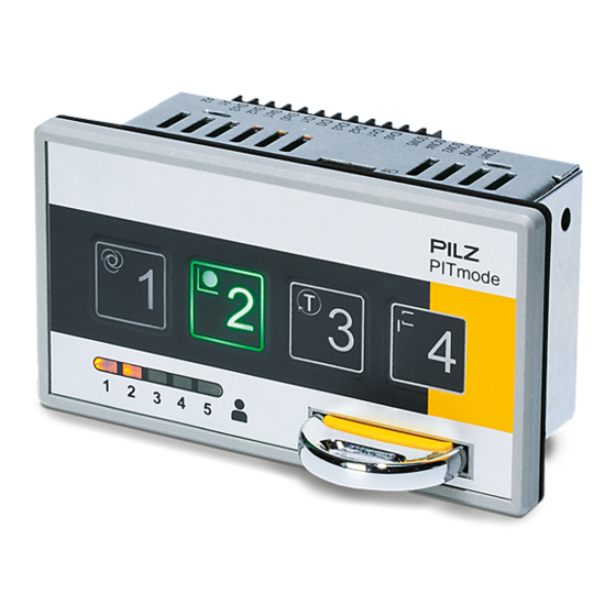
Overview Control elements Fig.: Front view Legend: Button to select an operating mode Button for OM1 / OM5 Button for OM2 Button for OM3 Button for OM4 Authorisation display – LEDs to display the authorisations for the relevant transpon der key Authorisation for OM1 Authorisation for OM2 Authorisation for OM3 Authorisation for OM4 Authorisation for OM5 Slot for inserting the transponder key Transponder key Operating Manual PIT m3.2p 1003176EN04... - Page 11 Overview 4 3 2 1 Fig.: View from above Legend: DIP switch for configuring the switching behaviour after the transponder key has been removed Operating Manual PIT m3.2p 1003176EN04...
-
Page 12: Safety
Safety Safety Intended use The operating mode selector switch is suitable for machines that can be operated in mul tiple operating modes with different protective measures and/or work procedures. It enables you to switch between defined operating modes, such as: Setup mode Manual mode Automatic mode Service The operating mode selector switch meets the following safety requirements: Interlock to protect against unauthorised switching Contact with a transponder key is required in order to switch to an operating mode. Access authorisations are restricted to certain groups A transponder key with the relevant authorisation is required in order to switch to a cer tain operating mode. Prevents unintentional switching The switch to a different operating mode is only recognised once the corresponding (selection) pushbutton has been operated for a defined period ("deliberate operator ac tion"). Multiple operation of (selection) pushbuttons is detected. Safe "1 from n" circuit of the operating mode outputs The operating mode selector switch only ever leads to one operating mode output "1" signal. Depending on the application area and its respective regulations, the operating mode se lector switch can be used up to SIL CL 2 (EN IEC 62061) and up to PL d (EN ISO 138491), if the operating modes are evaluated by a safety control system with safe "1oon" evaluation. Switching must not initiate a hazardous movement, nor can it cancel an existing control command. Operating Manual PIT m3.2p 1003176EN04... -
Page 13: Safety Regulations
Safety Safety regulations 3.2.1 Use of qualified personnel The products may only be assembled, installed, programmed, commissioned, operated, maintained and decommissioned by competent persons. A competent person is someone who, because of their training, experience and current pro fessional activity, has the specialist knowledge required to test, assess and operate the work equipment, devices, systems, plant and machinery in accordance with the general standards and guidelines for safety technology. It is the company’s responsibility only to employ personnel who: Are familiar with the basic regulations concerning health and safety / accident preven tion Have read and understood the information provided in this description under "Safety" And have a good knowledge of the generic and specialist standards applicable to the specific application. 3.2.2 Warranty and liability All claims to warranty and liability will be rendered invalid if The product was used contrary to the purpose for which it is intended Damage can be attributed to not having followed the guidelines in the manual Operating personnel are not suitably qualified Any type of modification has been made (e.g. exchanging components on the PCB boards, soldering work etc.). 3.2.3 Disposal In safetyrelated applications, please comply with the mission time T in the safetyre lated characteristic data. When decommissioning, please comply with local regulations regarding the disposal of electronic devices (e.g. Electrical and Electronic Equipment Act). Operating Manual PIT m3.2p 1003176EN04... -
Page 14: Function Description
Function description Function description The operating mode selector switch enables you to switch between 5 different operating modes (operating modes OM1 ... OM4 and special operating mode OM5 (Service)). For OM1 ... OM4, one button each is available. For the special operating mode (Service), button OM1 must be operated for a certain period (see Monitoring of operating time [ 50]). Each button is assigned a monitored semiconductor output. Operating the button changes the semiconductor output from a "0" signal to a "1" signal. The operating mode selector switch guarantees that only one of the semiconductor outputs has a "1" sig nal at any one time. Terminals Power SOM1 SOM2 Transponder Key SOM3 RFID SOM4 Receiver SOM5 IDo0 User Interface IDo1 IDo2 IDo3 IDi0 Inputs IDi1 SIo0 SIo1 SIo2 SIo3 Fig.: Block diagram Legend: Transponder Key Electronic key to enable a change of operating mode User Interface Button to select the operating mode Authorisation display (LEDs to display the authorisations for the relevant transponder key) - Page 15 Function description A1, A2 Supply voltage SOM1 … SOM5 Operating mode interface Interface to display the operating mode that is currently selected, consisting of 5 monitored outputs IDo0 … IDo3 and Key ID interface IDi0 … IDi1 Interface to download the Key ID number to a control system, consisting of 4 outputs and 2 inputs SIo0 … SIo3 Interface for status information Interface to signal status information, consisting of 4 signal outputs The operating mode selector switch is protected against unauthorised operation. A switch between operating modes must be enabled via a transponder key. Authorisations of a transponder key A total of 5 transponder keys are available for an operating mode selector switch. Each transponder key provides authorisation to switch up to 5 operating modes, including special authorisations. A transponder key can be identified via the printed key mode. Assignment of key modes to authorisations Designation Marking on transponder key Authorisation for operating mode Key Mode 01 Key Mode 02 OM1 + OM2 Key Mode 03 OM1 + OM2 + OM3 Key Mode 04 OM1 + OM2 + OM3 + OM4 Key Service Service OM1 + OM2 + OM3 + OM4 + OM5 (Service) Operating Manual PIT m3.2p 1003176EN04...
-
Page 16: Interface For Status Information
Function description Interface for status information Various status information can be signalled via the interface for status information (see Block diagram [ 14]). The status information can be evaluated through a control system. The status information is subdivided into the following information classes: Operator actions – Insert transponder key – Remove transponder key – Select operating mode Messages (e.g. user error, fault) NOTICE When the operating mode is selected (SIo3 … SIo0 = 3h, 8h ... Bh) and when there is a device error (Dh) the information remains indefinitely present. All other information stays active for just 200 ms. After that time the selected operating mode is again displayed. Value SIo3 SIo0 Status information Information class (MSB) SIo2 SIo1 (LSB) Hex) Reserved Reserved Transponder key 5 – Inserted [1] Operator action OM5 selected Operator action Transponder key 1 – Inserted [1] Operator action Transponder key 2 – Inserted [1] Operator action Transponder key 3 – Inserted [1] Operator action... - Page 17 Function description [1] When a pushbutton is released, information as to which transponder key is used will be displayed for 200 ms (see Status information 2h and 4h … 7h). The selected operating mode is then displayed (see Status information 3h and 8h … Bh). Please refer to the Timing diagrams for operator actions [ 18]. [2] The fault "No authorisation" (Ch) is registered in the following cases: Operating mode selected without transponder key Operating mode selected with a transponder key that is not authorised for the selected operating mode Transponder key is not authorised for the active operating mode Transponder key is not inserted in time before the operating mode is selected Please refer to the Timing diagrams for user error: "No authorisation" [ 21]. [3] "Device error" (Dh) is signalled in the event of an internal device error or when one of the operating mode outputs SOM1... SOM5 are stuck because of external voltage (stuck at1 or stuckat0). Remedy: Rectify error, switch supply voltage off and then on again Change the unit Please refer to the Timing diagram for device error [ 20]. [4] The fault "Pushbutton operated incorrectly" (Eh) is displayed in the following cases: Multiple operation of pushbuttons Pushbutton operated for too long (timeout for OM1 to OM4 = 5 s and timeout for OM5 = 10 s) Note: If a key is operated for < 50 ms this will not be evaluated, so there will be no re action. Pushbutton was released after the transponder key was removed Please refer to the Timing diagrams for user error: "Button operated incorrectly" [ 23]. Operating Manual PIT m3.2p 1003176EN04...
-
Page 18: Timing Diagrams For Operator Actions
Function description 4.1.1 Timing diagrams for operator actions The following timing diagram shows how status information is registered at outputs Slo0 ... Slo3, based on operator actions. Legend: Message is displayed constantly Message is displayed briefly (200 ms) Select operating mode 1. Start position: – OM1 selected – DIP switch in default setting 2. Operator action: Insert transponder key (e.g. Authorisation Key Mode 02) 3. Operator action: Select operating mode (e.g. Press button "2" for OM2) 4. Operator action: Remove transponder key Fig.: Timing diagram for "Select operating mode" with DIP switch setting [1] (default setting) Operating Manual PIT m3.2p 1003176EN04... - Page 19 Function description Remove transponder key 1. Start position: a OM5 is selected and the transponder key "Key Service" is inserted a One of the operating modes OM1 ... OM4 is selected and a transponder key with the relevant authorisation is inserted 2. Operator action: Remove transponder key Fig.: Timing diagram for "Remove transponder key" with DIP switch setting [1] (default setting) Fig.: Timing diagram for "Remove transponder key" with DIP switch setting [2] Fig.: Timing diagram for "Remove transponder key" with DIP switch setting [3] Operating Manual PIT m3.2p 1003176EN04...
-
Page 20: Timing Diagram For Device Error
Function description 4.1.2 Timing diagram for device error The following timing diagram shows how status information is registered at outputs Slo0 ... Slo3, based on a device error. Legend: Message is displayed constantly Message is displayed briefly (200 ms) Device error Fig.: Timing diagram in the event of a device error Operating Manual PIT m3.2p 1003176EN04... -
Page 21: Timing Diagrams For User Error: "No Authorisation
Function description 4.1.3 Timing diagrams for user error: "No authorisation" The following timing diagram shows how status information is registered at outputs Slo0 ... Slo3, based on the user error "No authorisation". Legend: Message is displayed constantly Message is displayed briefly (200 ms) Operating mode selected without transponder key Fig.: Timing diagram for "Operating mode selected without transponder key" Operating mode selected with a transponder key that is not authorised for the selec ted operating mode Fig.: Timing diagram for operating mode selection where there is insufficient authorisation for the op erating mode requiring selection Operating Manual PIT m3.2p 1003176EN04... - Page 22 Function description Operating mode selected with a transponder key that is not authorised for the active operating mode SIo3:0 Pushbutton Key Mode 01 Fig.: Timing diagram for operating mode selection where there is insufficient authorisation for the act ive operating mode Transponder key is not inserted in time before the operating mode is selected SIo3:0 Pushbutton „2" Key Mode 02 Fig.: Timing diagram for selecting the operating mode before the transponder key is inserted Operating Manual PIT m3.2p 1003176EN04...
-
Page 23: Timing Diagrams For User Error: "Button Operated Incorrectly
Function description 4.1.4 Timing diagrams for user error: "Button operated incorrectly" The following timing diagram shows how status information is registered at outputs Slo0 ... Slo3, based on the user error "Button operated incorrectly" Legend: Message is displayed constantly Message is displayed briefly (200 ms) Multiple operation of pushbuttons Fig.: Timing diagram for "Multiple operation of buttons" Operating Manual PIT m3.2p 1003176EN04... - Page 24 Function description Button operated for too long "Button operated for too long" with authorisations "Key Mode 01" … "Key Mode 04" "Button operated for too long" with authorisation "Key Service" SIo3:0 SIo3:0 Pushbutton Pushbuttons 10 s „1" „1" … „4" Key Service Key Mode 04 Fig.: Timing diagram for "Button operated for too long" Pushbutton was released after the transponder key was removed SIo3:0 Pushbutton „2" Key Service Fig.: Timing diagram for user errors when releasing the button Operating Manual PIT m3.2p 1003176EN04...
-
Page 25: Operating Mode Interface
Function description Operating mode interface The operating mode interface consists of the monitored outputs SOM1 … SOM5 (seeBlock diagram [ 14]). "SOM" stands for "Safe Operating Mode". The outputs are assigned to buttons, which can be used to select an operating mode if they have the relevant authorisa tion (transponder key): Pushbutton Output Operating mode SOM1 The operating mode OM1/OM5 is selected based on the operating time of button 1 (see SOM5 Monitoring of operating time [ 50]) SOM2 SOM3 SOM4 4.2.1 Switch behaviour after a transponder key is removed If the transponder key is removed after changing to a different operating mode, it is possible to configure the subsequent switch behaviour of SOM1 … SOM5. A DIP switch is available for this purpose (see Control elements [ 10]). NOTICE Please note the following: – The configuration may only be performed by a competent person. – The configuration must be performed when the supply voltage is switched off. – The configuration is adopted as the device is started up, provided the switch setting is valid. If not, the device switches to a "Device error" fault condition. – During operation, the DIP switch setting is monitored for any change. If the switch setting is changed during operation, the device switches to a "Device error" fault condition. Operating Manual PIT m3.2p 1003176EN04... - Page 26 Function description Configuration options via the DIP switch Operating mode Behaviour after the transponder DIP switch setting currently selected Assigned output key is removed [1]: Default setting SOM1 Operating mode currently se 4 3 2 1 lected is maintained SOM2 The assigned button is backlit. SOM3 The assigned output has a "1" SOM4 signal SOM5 Switch to OM1 Button 1 is backlit SOM1 has a "1" signal SOM1 Operating mode currently se 4 3 2 1 lected is maintained SOM2 OM1 … OM4: The assigned SOM3 button is backlit. SOM4 OM5: All 4 buttons flash. SOM5 The assigned output has a "1"...
-
Page 27: Control Program Requirements
Function description 4.2.2 Control program requirements In order to achieve SIL CL 2 (EN IEC 62061)/PL d (EN ISO 138491) in an application, the evaluation must be carried out by a safetyrelated function block. The safetyrelated func tion block must meet the following requirements: The function block must enable safe "1oon" evaluation of the output signals at SOM1 ... SOM5. If two or more operating modes are present at the same time, this must be detected as an error. INFORMATION The function block must bridge the t1 switchover delay (see Switchover delay t1 [ 50]). If a PNOZmulti (e.g. PNOZ m1p) is used as the safety control system in conjunction with an "operating mode selector switch" function element, then this requirement is met automatically. Operating Manual PIT m3.2p 1003176EN04... -
Page 28: Key Id Interface
Function description Key ID interface The Key ID interface (see Block diagram [ 14]) is used to download the Key ID number to a control system. 4.3.1 Key ID number of the transponder key The Key ID number is used to clearly identify the transponder key and is unique. It is prin ted on the transponder key’s type label as a 9digit decimal figure. NOTICE Please note: The Key ID number is not printed on the transponder key packaging. If the transponder key is lost, it is impossible to supply a replacement transponder key with an identical Key ID number. The Key ID number consists of two parts: Bit 27 = 24: Key Mode (0 … 15 Bit 23 = 00: Consecutive number (0 … 999999999 Bit27 ... Bit24 Bit23 ... Bit16 Bit15 ... Bit08 Bit07 ... Bit00 0 ... 15 0 ... 999999999 Key Mode Bit27 Bit26 Bit25 Bit24 Consecutive Number Service Fig.: Structure of the Key ID number... - Page 29 Function description Examples: Key-ID-Number: 130000044 1101 0000 0000 0000 0000 0010 1100 Key Mode Service Consecutive number: 44 Key-ID-Number: 020000510 0010 0000 0000 0000 0001 1111 1110 Consecutive number: 510 Key Mode 02 Operating Manual PIT m3.2p 1003176EN04...
-
Page 30: Communication Mode For Downloading The Key Id Number
Function description 4.3.2 Communication mode for downloading the Key ID number The unique Key ID number for the relevant transponder key is downloaded to the higher level process control system using a defined protocol, depending on the configured com munication mode. The communication mode is configured on the Key ID interface of the operating mode selector switch (jumpers available/not available). The operating mode selector switch detects the configured communication mode at each poweron. As long as voltage is applied to the operating mode selector switch, the con figured communication mode will be active; the change in communication mode does not come into effect until the supply voltage is switched off and then on again. It’s possible to choose between the following communication modes: Transmittercontrolled communication mode Handshakecontrolled communication mode 4.3.2.1 Transmittercontrolled communication mode With transmittercontrolled communication mode, the download of the Key ID number is started by the operating mode selector switch (= transmitter). Features of this communication mode: Download of Key ID number starts once the transponder key is connected Constant bit rate (100 ms) Download on 2 data lines Constant download time (typ. 1.8 s) Monitored data download Input/outputs required on the control system: 4 inputs and 2 outputs Download is repeated by reconnecting the transponder key No special coding is required on the Key ID interface in order to download the Key ID num ber of a transponder key to the control system in transmittercontrolled communication mode. The terminals on the Key ID interface are used as follows: Brief description of applic Key ID interface ation Coding via jumpers IDo0 IDsync No configuration required IDo1 IDclock IDo2 IDout0 IDo3 IDout1 IDi0... - Page 31 Function description 4.3.2.2 Handshakecontrolled communication mode With handshakecontrolled communication mode, the download of the Key ID number is started by the control system (Request). Features of this communication mode: Download starts via a request to the control system, once the transponder key is con nected Download is repeated by a renewed request to the control system Variable bit rate (min. 2 PLC cycles per bit) Download on 1 data line Min. download time: 28 Bit * (20 ms + 2 * PLC cycle) Identifier for ID end for feasibility check Input/outputs required on the control system: 3 inputs and 1 output The Key ID interface must be coded with a jumper between IDo3 and IDi1 in order to down load the Key ID number of a transponder key to the control system in handshakecontrolled communication mode. The terminals on the Key ID interface are used as follows: Brief description of applic Key ID interface ation Coding via jumpers IDo0 IDsync IDo1 IDresponse IDo2 IDdata IDo3 Coding: OUT IDo3 Coding: OUT IDi0 IDrequest IDi1 Coding: IN IDi1 Coding: IN In handshakecontrolled communication mode, the operating mode selector switch can be operated in a functional variant. In this case the Key ID number of the transponder key is not downloaded to the control system. The control system is only used to evaluate IDo0 on the Key ID interface. In this case IDo0 is used as a signal output, enabling the control sys...
-
Page 32: Evaluation By A Control System
Function description 4.3.3 Evaluation by a control system 4.3.3.1 Evaluation of the Key ID number with transmittercontrolled communication max. 100 ms min. 60 ms IDo0 (IDsync) IDo1 (IDclock) IDo2 Bit 25 … Bit 16 Bit 27 Bit 26 Bit 15 Bit 14 (IDout0) IDo3 Bit 11 … Bit 02 Bit 13 Bit 12 Bit 11 Bit 00 (IDout1) - Page 33 Function description Download procedure The operating mode selector switch sets the signal at IDo0 (IDsync: control line) to "1" for 100 ms, thereby signalling to the control system that transmis sion has started. A rising edge at IDo1 (IDclock: test pulse line) indicates that the data at data lines IDo2 and IDo3 is present and valid and can be read by the control sys tem. By the time there is a falling edge at IDo1 (IDclock: test pulse line), the control system must have sent the previously read bit back to the operating mode se lector switch via the data lines IDi0 and IDi1. Before the rising edge at IDo1 (IDclock: test pulse line), the operating mode selector switch reads the bits sent back to IDi0 and IDi1 by the control system and checks it for equivalence. At least 60 ms after the falling edge at IDo1 (IDclock: test pulse line), the last bit sent back by the control system must be present at data lines IDi0 and IDi1. A maximum of 100 ms after the falling edge at IDo1 (IDclock: test pulse line), the last bit sent back by the control system must be present at data lines IDi0 and IDi1; in other words, by this point at the latest, data transfer must be com pleted and the data lines must have a "0" signal. INFORMATION If the control system does not feed back the previously read Bits correctly, the download is aborted and restarted. The "IDsync" signal is set once again. The download is repeated until the Key ID number is downloaded completely. The download of the Key ID number typically takes 1.8 s. Operating Manual PIT m3.2p 1003176EN04...
- Page 34 Function description Flowchart for evaluating the Key ID interface See Fig. „Timing Diagramm Start of sender controlled signal transfer“ <IDsync> = 1 <IDsync> = 0 Clear Bit Counter <IDsync> = 1 <IDclock> = 1 Read <IDout0> AND <IDout1> Increment Bit Counter Set <IDin0> = <IDout0> Set <IDin1> = <IDout1> <IDclock>...
-
Page 35: Evaluation Of The Key Id Number With Handshakecontrolled Communica
Function description 4.3.3.2 Evaluation of the Key ID number with handshakecontrolled communication IDend 200 ms IDo0 (IDsync) IDo1 (IDresponse) IDo2 Bit 25 … Bit 02 Bit 27 Bit 26 Bit 01 Bit 00 (IDdata) IDi0 (IDrequest) Fig.: Timing diagram for handshakecontrolled signal download Legend: The additional terminal designations (IDsync, IDresponse, IDdata and IDrequest etc.) are abbreviations for the terminal signal's application. IDo0 Control line The signal is generated by the operating mode selector switch. "0" signal No transponder key is connected or the transponder key that is con nected is invalid. The control system cannot request the Key ID number. "1" signal A valid transponder key is connected and the control system can re quest the Key ID number. - Page 36 Function description End of Key ID Number Transfer (200 ms) IDend After the last falling edge at IDi0, the operating mode selector switch still has a "1" signal at output IDo1 for 200 ms. In this way, the end of the Key ID number and therefore the end of the download (End of Key ID Number Transfer) is dis played. This can be used for the feasibility check. Download procedure "1" signal at IDo0 (control line): A valid transponder key is present at the operating mode selector switch. "1" signal at IDi0 (handshake line): The control system requests a data bit at data line IDo2 an (= Request). "1" signal at IDo1 (handshake line): The operating mode selector switch confirms the validity of the data bit at data line IDo2 (= Response). "0" signal at IDi0 (handshake line): The control system confirms that it has read the requested data bit without error. "0" signal at IDo1 (handshake line): The operating mode selector switch is ready to issue a new data bit at data line IDo2. "0" signal at IDo0 (control line): The transponder key has been removed. The control system must request all the data bits of a Key ID number (Bit27 … Bit00). Only then is it possible to start downloading a new Key ID number. The end of the download is indicated by the signal extension (t ) at IDo1. IDend Operating Manual PIT m3.2p 1003176EN04...
- Page 37 Function description Status diagram for handshakecontrolled signal download Fig.: Status diagram for handshakecontrolled signal download Operating Manual PIT m3.2p 1003176EN04...
- Page 38 Function description Flowchart for evaluating the Key ID interface See Fig. „State diagram Start of handshake controlled signal transfer“: Requirement See Fig. „Timing diagram Set Bit Counter = 0 of handshake controlled signal transfer“: sync <ID > = 1 response <ID > = 0 Bit Request request Set <ID >= 1 Data Read and...
-
Page 39: Installation
Installation Installation General installation guidelines The installation site must conform to the protection type IP54. Ensure that the operating mode selector switch has sufficient ventilation. Attach the operating mode selector switch using the brackets provided. Make sure that the gasket is seated correctly. Operating Manual PIT m3.2p 1003176EN04... -
Page 40: Dimensions
Installation Dimensions Front view View from below Operating Manual PIT m3.2p 1003176EN04... -
Page 41: Mounting Cutout
Installation Mounting cutout 84.2 Operating Manual PIT m3.2p 1003176EN04... -
Page 42: Wiring
Wiring Wiring Terminal configuration INFORMATION The connection terminals are not supplied with the unit. Fig.: Terminal configuration Legend SOM1 .. SOM5 Operating mode interface: Monitored semiconductor outputs for the op erating modes OM1 … OM5 IDo0 … IDo3 Key ID interface: Semiconductor outputs for sending the output signals to the control system The function of the terminals depends on the communication mode that has been configured. IDi0 … IDi1 Key ID interface: Inputs for receiving the input signals from the control system The function of the terminals depends on the communication mode that has been configured. SIo0 … SIo3 Interface for status information Evaluation of status information A1, A2 Terminals for connecting the supply voltage Functional earth Operating Manual PIT m3.2p 1003176EN04... -
Page 43: Connecting The Unit
Wiring Connecting the unit Proceed as follows: 1. Connecting the supply voltage a Connect the supply voltage to (A1, A2). Please note the following: The power supply must meet the regulations for extra low voltages with protective separation (SELV, PELV). The cables for the unit's supply voltage (A1, A2) must be fitted with a 4 A fuse, characteristic B/C. 2. Connecting the operating mode interface's semiconductor outputs a Connect the operating mode interface's semiconductor outputs to a control system that supports "1ooN" evaluation. You must read the information concerning intended use (see Intended use [ 12]). 3. Connecting the interface's terminals for status information a Connect the terminals (SIo0 ... SIo3) to a control system that supports evaluation of the status information. 4. Configure communication mode for downloading the Key ID number a To download the Key ID number in handshakecontrolled communication mode, connect terminals IDo3 and IDi1 of the Key ID interface. No configuration is required for transmittercontrolled communication mode. 5. Connecting the terminals of the Key ID interface a Depending on the selected communication mode, connect the terminals of the Key ID interface to a control system that supports the download of the Key ID number. a Connect IDo0 to a control system, if all you wish to do in handshakecontrolled communication mode is evaluate whether the transponder key is valid/invalid. In this case you will only use IDo0 as a signal output. The unused terminals on the Key ID interface (IDo1, IDo2 and IDi0) may remain unwired ("open"). -
Page 44: Connection To A Control System
Wiring Connection to a control system Depending on the application area and its respective regulations, the operating mode se lector switch can be used up to SIL CL 2 (EN IEC 62061) and up to PL d (EN ISO 138491), if the operating modes are evaluated by a safety control system with safe "1oon" evaluation. The examples below meet the following conditions: A PNOZ m1p is used as a safety control system. An "operating mode selector switch" function element is configured in the PNOZmulti Configurator for safe "1oon" evaluation. The Key ID interface and the interface for status information are evaluated via a higher level process control system. The cables for the unit's supply voltage (A1, A2) contain a 4 A fuse, characteristic B/C. Operating Manual PIT m3.2p 1003176EN04... - Page 45 Wiring Connection for transmittercontrolled communication mode Fig.: Connection for transmittercontrolled communication mode (example) Operating Manual PIT m3.2p 1003176EN04...
- Page 46 Wiring Connection for handshakecontrolled communication mode Fig.: Connection for handshakecontrolled communication mode (example) Operating Manual PIT m3.2p 1003176EN04...
- Page 47 Operation Operation Switchon behaviour INFORMATION After the operating mode selector switch is switched on (Power ON) or after voltage is returned (reset), operating mode OM1 is selected automatically. This also applies if no transponder key is connected, or a transponder key is detected but is invalid. Behaviour in the event of an error in operating modes OM1 … OM4 NOTICE In the event of an error, the unit does not change operating mode. The act ive operating mode (OM1, OM2, OM3 or OM4) is displayed via the backlit button and the assigned semiconductor output has a 1 signal. Behaviour in the event of an error in special operating mode OM5 (Service) NOTICE In the event of an error, the unit does not change operating mode. Faulty operation is indicated by the fact that all buttons are either all lit or all out. The assigned semiconductor output has a 1 signal. Operating Manual PIT m3.2p 1003176EN04...
-
Page 48: Select Operating Modes Om1
Operation Select operating modes OM1 ... BA4 Prerequisites A transponder key with the relevant authorisations must be present. The operating mode selector switch must recognise the transponder key as valid. The transponder key must be present at the operating mode selector switch for the whole time the button is operated. Several buttons may not be operated simultaneously when selecting an operating mode. Procedure 1. Establish the connection with the transponder key a Insert the transponder key into the slot. Note: The transponder key must support the operating mode/operating modes into which you wish to switch. The authorisation display LEDs provide information about the authorisations available with the relevant transponder key (see Control elements [ 10]). 2. Select operating mode a Select the required operating mode by pressing the relevant button. Please note the required operating time (see Monitoring of operating time [ 50]). The operating mode has been selected correctly if the button is rear lit once it is released. 3. Complete operating mode selection a Complete the operating mode selection by removing the transponder key. Once you have removed the transponder key, the operating mode selector switch behaves in accordance with the configuration (see Switch behaviour after a transponder key is removed [ 25]). INFORMATION You can switch at will between the individual operating modes OM1, OM2, OM3 and OM4; i.e. it is possible to switch from OM1 to OM3 or from OM4 to OM2, for example. Operating Manual PIT m3.2p 1003176EN04... -
Page 49: Select Special Mode (Service)
Operation Select special mode (service) Prerequisites A transponder key must be available with authorisation for special operating mode OM5 (Service). The operating mode selector switch must recognise the transponder key as valid. The transponder key must be present at the operating mode selector switch for the whole time the button is operated. Several buttons may not be operated simultaneously when selecting an operating mode. Procedure 1. Establish the connection with the transponder key a Insert the transponder key "Key Service" into the slot. Note: All authorisation display LEDs must light (see Control elements [ 10]). 2. Select special mode OM5 (Service) a Press button 1 (OM1). Please note the required operating time (see Monitoring of operating time [ 50]). The operating mode has been selected correctly if all the buttons flash when button 1 is released. The buttons flash for as long as they are in special operating mode OM5 (Service). 3. Complete operating mode selection a Complete the operating mode selection by removing the transponder key. Once you have removed the transponder key, the operating mode selector switch behaves in accordance with the configuration (see Switch behaviour after a transponder key is removed [ 25]). INFORMATION Special operating mode OM5 (Service) can be selected from any of the op erating modes. Operating Manual PIT m3.2p 1003176EN04... -
Page 50: Monitoring Of Operating Time
Operation Monitoring of operating time A change of operating modes is only detected if the relevant button has been operated for a defined time period. Button's operating time Pushbut Operating mode Output Operating time SOM1 > 50 ms and < 5 s SOM2 SOM3 SOM4 OM5 (Service) SOM5 > 5 s and < 10 s Switchover delay t1 Once a button has been released, the assigned output on the operating mode interface switches to a "1" signal after the switchover delay t1 has elapsed (see Technical details [ 54]). This defined switchover delay guarantees that only one operating mode at a time has a "1" signal at the assigned output. SOM1 SOM2 SOM3 SOM4 SOM5 Fig.: Time behaviour when switching operating mode Operating Manual PIT m3.2p 1003176EN04... -
Page 51: Troubleshooting
Operation Troubleshooting If an error occurs on the operating mode selector switch, the last operating mode to be set will be retained. Error Possible cause Remedy Unable to switch the Multiple operation of but Make sure that only one button is operating mode tons operated Operating time too long or Make sure that the period of opera too short tion is observed. Transponder key is not de Make sure that the transponder key tected is connected to the operating mode selector switch or inserted correctly. No valid authorisation Make sure that you use a transpon der key that has the required au thorisation Operating Manual PIT m3.2p 1003176EN04... -
Page 52: Diagnostics
Operation Diagnostics The operating mode selector switch has various options for displaying status information: Interface for status information (SIo0 … SIo3) Button backlighting Authorisation display (LEDs 1 … 5) 7.6.1 Status information about the interface for status information Various status information can be signalled via the interface for status information (see Block diagram [ 14]). The status information can be evaluated through a control system (see Interface for status information [ 16]). 7.6.2 Status information about button backlighting Pushbuttons 1 … 4 (see Control elements [ 10]) have pushbutton backlighting. Pushbut ton backlighting is used to indicate which operating mode is active; in other words, which output (SOM 1 ... SOM5) has a "1" signal. Evaluation of pushbutton backlighting Legend: LED on LED flashes LED off LED pushbut LED pushbut LED pushbut LED pushbut ton 1 ton 2 ton 3 ton 4 Meaning No supply voltage OM 5 (Service) is active SOM1 has a "1" signal OM 1 is active SOM1 has a "1" signal OM 2 is active SOM2 has a "1" signal OM 3 is active SOM3 has a "1" signal OM 4 is active... -
Page 53: Status Information Via Authorisation Display
Operation 7.6.3 Status information via authorisation display If a transponder key is inserted in the slot of the operating mode selector switch, its author isations are displayed via the authorisation display LEDs (see Control elements [ 10]). Evaluation of LED signals Legend: LED on LED off Status Meaning All LEDs No transponder key connected or Authorisation not recognised, or not recognised fully Authorisation available for OM1 ... OM5 LED "1" No authorisation for OM1 Authorisation available for OM1 LED "2" No authorisation for OM2 Authorisation available for OM2 LED "3" No authorisation for OM3 Authorisation available for OM3 LED "4" No authorisation for OM4 Authorisation available for OM4 LED "5" No authorisation for OM5 Authorisation available for OM5 Operating Manual PIT m3.2p 1003176EN04... -
Page 54: Technical Details
Technical details Technical details General Approvals CE, FCC, IC, TÜV, cULus Listed Sensor's mode of operation Transponder Transponder interface Energy supply to transponder passive (battery free) Operating frequency 125 kHz Electrical data Supply voltage Voltage 24,0 V Kind Voltage tolerance 15 %/+10 % Output of external power supply (DC) 1,0 W Residual ripple DC 20 % Continuous duty 100 % Status indicator Inputs Number Signal level at "0" 3 +5 V DC Signal level at "1" 15 30 V DC Voltage at inputs 24 V DC Input current range 2,0 mA Galvanic isolation Semiconductor outputs Overall performance ext. loading, semiconductor 3,5 W Number of positiveswitching singlepole semicon... - Page 55 Technical details Environmental data Storage temperature Temperature range 25 70 °C Climatic suitability In accordance with the standard EN 60068278 Humidity 95 % r. h. at 40 °C EN 6094751 Vibration In accordance with the standard EN 6006826 Frequency 10,0 55,0 Hz Amplitude 0,35 mm Airgap creepage In accordance with the standard EN 606641 Overvoltage category Pollution degree Rated insulation voltage 60 V Rated impulse withstand voltage 0,80 kV Protection type Mounting area (e.g. control cabinet) IP64 Housing IP20 Terminals IP20 Mechanical data Operating distances Typical operating distance So 5,0 mm Max. cable length 1000 m Material Bottom ST + 10µ Zn...
-
Page 56: Safety Characteristic Data
Technical details Safety characteristic data Operating EN ISO EN ISO EN 62061 EN 62061 IEC 61511 IEC 61511 EN ISO mode 138491: 138491: 138491: SIL CL [1/h] 2008 2008 2008 Category [year] – PL d Cat. 3 SIL CL 2 1,10E08 SIL 2 5,28E04 All the units used within a safety function must be considered when calculating the safety characteristic data. INFORMATION A safety function's SIL/PL values are not identical to the SIL/PL values of the units that are used and may be different. We recommend that you use the PAScal software tool to calculate the safety function's SIL/PL values. Operating Manual PIT m3.2p 1003176EN04... -
Page 57: Supplementary Data
2) this product must accept any interference received, including interference that may cause undesired operation. Changes or modifications made to this product not expressly approved by Pilz may void the FCC authorization to operate this equipment. NOTE: This equipment has been tested and found to comply with the limits for a Class A digital device, pursuant to Part 15 of the FCC Rules. -
Page 58: Order Reference
Order reference Order reference 10.1 Product Type Features Order no. PIT m3.2p Operating mode selector switch 402 230 PIT m3.2p machine tools pic Operating mode selector switch 402 231 togram 10.2 Accessories Terminals Type Features Order no. Springloaded terminals 1 set 402 302 Angled screw terminals 1 set 402 303 Screw terminals 1 set 402 305 Transponder key Type Features Order no. PIT m3 key mode 1 Transponder Key Mode 01 402 211 PIT m3 key mode 2 Transponder Key Mode 02 402 212 PIT m3 key mode 3 Transponder Key Mode 03 402 213 PIT m3 key mode 4... - Page 59 Front cover Support Technical support is available from Pilz round the clock. Americas Australia Scandinavia Brazil +61 3 95446300 +45 74436332 +55 11 97569-2804 Spain Canada Europe +34 938497433 Switzerland +1 888-315-PILZ (315-7459) Austria +43 1 7986263-0 +41 62 88979-30 Mexico...