Table of Contents
Advertisement
Quick Links
Advertisement
Table of Contents

Related Manuals for Pilz PIT m3.3p


Summary of Contents for Pilz PIT m3.3p
- Page 1 PIT m3.3p Control and signal devices Operating Manual-1003190-EN-08...
- Page 2 Preface This document is a translation of the original document. All rights to this documentation are reserved by Pilz GmbH & Co. KG. Copies may be made for internal purposes. Suggestions and comments for improving this documentation will be gratefully received.
- Page 3 Evaluation of the Key ID number with handshake-controlled communica- tion 4.4.3.3 Evaluation of the Key ID number with advanced communication Operating mode lock and operating mode preselection 4.5.1 Operating mode lock 4.5.2 Operating mode pre-selection Section 5 Installation General installation guidelines Dimensions Operating Manual PIT m3.3p 1003190-EN-08...
-
Page 4: Table Of Contents
Section 8 Technical details Safety characteristic data Section 9 Supplementary data Radio approval Chemical resistance 9.2.1 Front membrane 9.2.2 Plastic frame Section 10 Order reference 10.1 Product 10.2 Accessories Section 11 EC declaration of conformity Operating Manual PIT m3.3p 1003190-EN-08... - Page 5 Validity of documentation This operating manual explains the function and operation, describes the installation and provides guidelines on how to connect the product. This documentation is valid for the product PIT m3.3p. It is valid until new documentation is published. 1.1.1 Retaining the documentation This documentation is intended for instruction and should be retained for future reference.
- Page 6 Introduction INFORMATION This gives advice on applications and provides information on special fea- tures. Operating Manual PIT m3.3p 1003190-EN-08...
- Page 7 1 semiconductor output per operating mode Interface for status information, consisting of 4 signal outputs (24 V) Status information is divided into information classes: – Operator actions - Insert transponder key - Remove transponder key - Select operating mode Operating Manual PIT m3.3p 1003190-EN-08...
- Page 8 A transponder key contains a Key ID number and the authorisations to which you can switch with that transponder key. Features: Replaces the mechanical key Different authorisations Authorisations are identified via printed "Key Mode". Unique identification of a certain transponder key via Key-ID number Operating Manual PIT m3.3p 1003190-EN-08...
- Page 9 Authorisation display – LEDs to display the authorisations for the relevant transpon- der key Authorisation for OM1 Authorisation for OM2 No function No function Authorisation for OM5 Slot for inserting the transponder key Transponder key Operating Manual PIT m3.3p 1003190-EN-08...
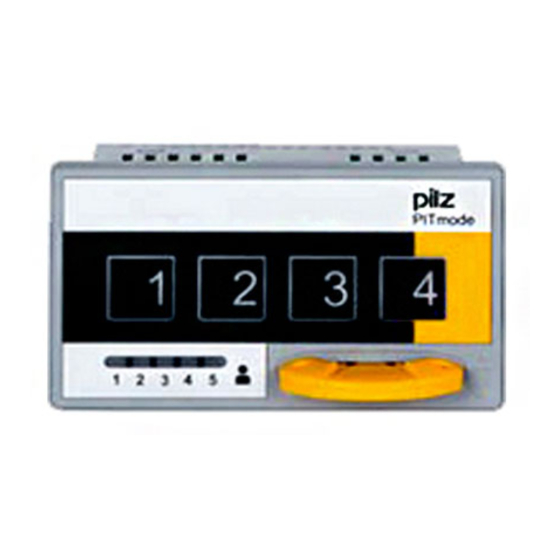
- Page 10 Explanation of front membrane There is a version of the operating mode selector switch with front membrane, for use with moulding machines. The front membrane contains symbols of the various operating modes. Fig.: PITm3.3p with front membrane Operating Manual PIT m3.3p 1003190-EN-08...
- Page 11 Overview The table below explains what the symbols mean: Operating mode Display Explanation Automatic mode (EN ISO 16090-1:2014) Set-up (EN ISO 16090-1:2014) Operating Manual PIT m3.3p 1003190-EN-08...
- Page 12 (EN ISO 13849-1), if the operating modes are evaluated by a safety control system with safe "1oon" evaluation. NOTICE Faulty operation of PITmode can lead to hazardous situations. Switching to an operating mode must not initiate a hazardous movement, nor can it can- cel an existing control command. Operating Manual PIT m3.3p 1003190-EN-08...
- Page 13 In safety-related applications, please comply with the mission time T in the safety-re- lated characteristic data. When decommissioning, please comply with local regulations regarding the disposal of electronic devices (e.g. Electrical and Electronic Equipment Act). Operating Manual PIT m3.3p 1003190-EN-08...
- Page 14 16]), after a restart the unit will start with the last selected operating mode. If OM storage is not configured, the unit always starts with OM1. For this reason you should make sure that OM1 represents the safest operating mode. Operating Manual PIT m3.3p 1003190-EN-08...
- Page 15 SOM1 … SOM5 Operating mode interface Interface for displaying the selected operating mode SOM1 Monitored output for OM1 SOM2 Monitored output for OM2 SOM3 No function SOM4 No function SOM5 Monitored output for OM5 (Service) Operating Manual PIT m3.3p 1003190-EN-08...
- Page 16 The communication modes have different functions. These functions are described in the following subsections: Transmitter-controlled communication mode [ Handshake-controlled communication mode [ Advanced communication mode [ Operating Manual PIT m3.3p 1003190-EN-08...
- Page 17 Sender or handshake- controlled communica- 4 3 2 1 tion mode OM fallback Sender or handshake- controlled communica- 4 3 2 1 tion mode OM storage Sender or handshake- controlled communica- 4 3 2 1 tion mode Operating Manual PIT m3.3p 1003190-EN-08...
- Page 18 DIP configuration NOTICE It is essential to note that only the DIP switch settings described above will be assessed as valid. With all other DIP switch settings, the device switches to a "Device error" fault condition. Operating Manual PIT m3.3p 1003190-EN-08...
- Page 19 "1" signal. NOTICE Switching of the operating mode to OM1 by removing the transponder key is not a safety-related function. Switching of the operating mode has to be val- idated in accordance with the requirements. Operating Manual PIT m3.3p 1003190-EN-08...
- Page 20 Various status information can be signalled via the interface for status information (see Block diagram [ 14]). The status information can be evaluated through a control system. The status information is subdivided into the following information classes: Operator actions – Transponder key inserted – Remove transponder key Operating Manual PIT m3.3p 1003190-EN-08...
- Page 21 [2] The error "No authorisation" (Ch) is registered in the following cases: Operating mode selected without transponder key Operating mode selected with a transponder key that is not authorised for the selected operating mode Transponder key is not authorised for the active operating mode Operating Manual PIT m3.3p 1003190-EN-08...
- Page 22 [5] In the configurations with DIP switch settings [5] … [8] the switching of operating mode outputs to the preselected operating mode is displayed for 200 ms during an operating mode preselection. This is used as a feedback for the control system. Operating Manual PIT m3.3p 1003190-EN-08...
- Page 23 (e.g. Authorisation Key Mode 02) 3. Operator action: Select operating mode (e.g. Press button "2" for OM2) 4. Operator action: Remove transponder key Fig.: Timing diagram for "Select operating mode" with DIP switch setting [1] (default setting) and [5] Operating Manual PIT m3.3p 1003190-EN-08...
- Page 24 Fig.: Timing diagram for "Remove transponder key" with DIP switch setting [1] (default setting) and 8h … 9h as before as before SIo3:0 SIo3:0 Key Mode 01 … 02 Key Service Fig.: Timing diagram for "Remove transponder key" with DIP switch setting [2], [4], [6] and [8] Operating Manual PIT m3.3p 1003190-EN-08...
- Page 25 Application error: "No authorisation" The following timing diagrams show how status information is registered at outputs Slo0 ... Slo3, based on the application error "No authorisation". Legend: Message is displayed constantly Message is displayed briefly (200 ms) Operating Manual PIT m3.3p 1003190-EN-08...
- Page 26 Operating mode selected with a transponder key that is not authorised for the selec- ted operating mode Fig.: Timing diagram for operating mode selection where there is insufficient authorisation for the op- erating mode requiring selection Operating Manual PIT m3.3p 1003190-EN-08...
- Page 27 Application error: "Pushbutton operated incorrectly" The following timing diagrams show how status information is registered at outputs Slo0 ... Slo3, based on the application error "Pushbutton operated incorrectly" Legend: Message is displayed constantly Message is displayed briefly (200 ms) Operating Manual PIT m3.3p 1003190-EN-08...
- Page 28 "Pushbutton operated for too long" with authorisations "Key Mode 01" … "Key Mode 02" "Pushbutton operated for too long" with authorisation "Key Service" SIo3:0 SIo3:0 Pushbutton Pushbuttons 10 s „1" „1" … „2" Key Service Key Mode 02 Fig.: Timing diagram for "Pushbutton operated for too long" Operating Manual PIT m3.3p 1003190-EN-08...
- Page 29 Please note: The Key ID number is not printed on the transponder key packaging. If the transponder key is lost, it is impossible to supply a replacement transponder key with an identical Key ID number. Operating Manual PIT m3.3p 1003190-EN-08...
- Page 30 Fig.: Structure of the Key ID number Examples: Key-ID-Number: 130000044 1101 0000 0000 0000 0000 0010 1100 Key Mode Service Consecutive number: 44 Key-ID-Number: 020000510 0010 0000 0000 0000 0001 1111 1110 Consecutive number: 510 Key Mode 02 Operating Manual PIT m3.3p 1003190-EN-08...
- Page 31 Brief description of ap- Assignment control sys- Key ID interface plication Coding IDo0 IDsync Input No coding required IDo1 IDclock Input IDo2 IDout0 Input IDo3 IDout1 Input IDi0 IDin0 Output IDi1 IDin1 Output Operating Manual PIT m3.3p 1003190-EN-08...
- Page 32 With this functional vari- ant, only 1 input is required on the control system. The unused terminals on the Key ID in- terface (IDresponse, IDdata and IDrequest) may remain unwired ("open"). Operating Manual PIT m3.3p 1003190-EN-08...
- Page 33 48]) on the Key ID interface are used as follows: Brief description of ap- Assignment control sys- Key ID interface plication Coding IDo0 IDresponse Input Configuration via DIP switch setting IDo1 IDrequest Output IDo2 IDdata Input IDo3 IDsync Input IDi0 keylock Output IDi1 Output Operating Manual PIT m3.3p 1003190-EN-08...
- Page 34 The control system sends the previously received Key ID number back to the operating mode selector switch via these two data lines. IDin0: Receive Bit 27 … Bit 14 IDin1 Receive Bit 13 … Bit 00 Operating Manual PIT m3.3p 1003190-EN-08...
- Page 35 The "IDsync" signal is set once again. The download is repeated until the Key ID number is downloaded completely. The download of the Key ID number typically takes 1.8 s. Operating Manual PIT m3.3p 1003190-EN-08...
- Page 36 Set <IDin1> = <IDout1> <IDclock> = 0 Bit Counter = 14 Start Last Bit Timer Last Bit Timer >= 60ms Clear <IDin0> AND <IDin1> Store ID-Number Fig.: Evaluation of the Key ID number via a control system (principle) Operating Manual PIT m3.3p 1003190-EN-08...
- Page 37 "1" signal A new bit is requested at IDdata. IDsync Enable Time (min. 0 ms) Data Output Valid Time (max. 10 ms) Data Output Hold Time (min. 0 ms) Data Output Access Time (max. 10 ms) Operating Manual PIT m3.3p 1003190-EN-08...
- Page 38 The control system must request all the data bits of a Key ID number (Bit27 … Bit00). Only then is it possible to start downloading a new Key ID number. The end of the download is indicated by the signal extension (t ) at IDresponse. IDend Operating Manual PIT m3.3p 1003190-EN-08...
- Page 39 Function description Status diagram for handshake-controlled signal download Fig.: Status diagram for handshake-controlled signal download Operating Manual PIT m3.3p 1003190-EN-08...
- Page 40 Last Bit Control <IDsync> = 0 <IDresponse> = 0 Time Control <t > >= 200ms IDend Bit Counter = 28 Store ID Number Fig.: Evaluation of the Key ID number via a control system (principle) Operating Manual PIT m3.3p 1003190-EN-08...
- Page 41 You can deactivate the function, although it is configured. To do this, connect a "1" signal to input IDi0. NOTICE The operating mode lock is not a safety-related function. Switching of the operating mode has to be validated in accordance with the requirements. Operating Manual PIT m3.3p 1003190-EN-08...
- Page 42 Fig.: Changing the operating mode after removing the transponder key, with DIP switch settings [7] Legend To assign the terminal designations to the short descriptions, please refer to the table in Advanced communication mode [ 33]. Acknowledge Time min. 120 ms. Operating Manual PIT m3.3p 1003190-EN-08...
- Page 43 "Operating mode preselection switched" (see Schnittstelle für Statusinformationen [ 20]) The pushbutton backlighting for the newly selected operating mode is lit continuously and the pushbutton backlighting for the last confirmed operating mode goes out. Operating Manual PIT m3.3p 1003190-EN-08...
- Page 44 SOM 1 SOM 2 Output OM1 selected [8h] [5h] OM2 selected [9h] OM1 selected [8h] SI3:0 Output SOM 1 Fig.: Exiting the operating mode preselection after operating the pushbutton, with DIP switch setting [5] to [8] Operating Manual PIT m3.3p 1003190-EN-08...
- Page 45 20 ms, in order to adopt the signal status. "0" signal Preventing the switching of operating mode outputs "1" signal Enabling the switching of operating mode outputs display SOM Pushbutton backlighting Output SI3:0 Interface for control information Output SOM Operating mode outputs Operating Manual PIT m3.3p 1003190-EN-08...
- Page 46 Do not exceed the max. torque setting of 0.30 Nm. The locking hooks can break off if the torque setting is too high. Make sure that the gasket is seated correctly. Please refer to the regulations in EN 60204-1 with regard to the protective earth sys- tem. Dimensions Front view Operating Manual PIT m3.3p 1003190-EN-08...
-
Page 47: Mounting Cutout
Installation View from below Mounting cutout 84.2 Operating Manual PIT m3.3p 1003190-EN-08... -
Page 48: Wiring
SOM5 Monitored semiconductor output for OM5 (Service) IDo0 … IDo3 Key ID interface: Semiconductor outputs for sending the output signals to the control system The function of the terminals depends on the communication mode that has been configured. Operating Manual PIT m3.3p 1003190-EN-08... -
Page 49: Connecting The Unit
In this case you will only use IDsync as a signal output. The unused terminals on the Key ID interface (IDresponse, IDdata and IDrequest) may remain unwired ("open"). Operating Manual PIT m3.3p 1003190-EN-08... -
Page 50: Connection To A Control System
Configurator for safe "1oon" evaluation. The Key ID interface and the interface for status information are evaluated via a higher- level process control system. The cables for the unit's supply voltage (A1, A2) contain a 4 A fuse, characteristic B/C. Operating Manual PIT m3.3p 1003190-EN-08... - Page 51 Wiring Connection for transmitter-controlled communication mode Fig.: Connection for transmitter-controlled communication mode (example) Operating Manual PIT m3.3p 1003190-EN-08...
- Page 52 Wiring Connection for handshake-controlled communication mode Fig.: Connection for handshake-controlled communication mode (example) Operating Manual PIT m3.3p 1003190-EN-08...
- Page 53 Wiring Connection for advanced communication mode Fig.: Connection for advanced communication mode (example) Operating Manual PIT m3.3p 1003190-EN-08...
-
Page 54: Operation
In the event of an error, the unit does not change operating mode. Faulty operation is indicated by the fact that all pushbuttons are either all lit or all out. The assigned semiconductor output has a "1" signal. Operating Manual PIT m3.3p 1003190-EN-08... -
Page 55: Select Operating Modes Om1/Om2
Once you have removed the transponder key, the operating mode selector switch behaves in accordance with the configuration (see Switch behaviour after a transponder key is removed [ 20]). INFORMATION You can switch between the individual operating modes at will. Operating Manual PIT m3.3p 1003190-EN-08... -
Page 56: Select Special Mode (Service)
A change of operating modes is only detected if the relevant button has been operated for a defined time period. Button's operating time Button Operating mode Output Operating time SOM1 > 50 ms and < 5 s SOM2 OM5 (Service) SOM5 > 5 s and < 10 s Operating Manual PIT m3.3p 1003190-EN-08... -
Page 57: Switchover Delay T1
(stuck-at-1 or stuck- at-0) Internal device error Switch supply voltage off and then on again, change unit if ne- cessary Please refer to the timing diagram for Device error [ 25]. Operating Manual PIT m3.3p 1003190-EN-08... -
Page 58: Delete Error
Configure DIP switch setting as shown (all switches to ON) 4 3 2 1 Device restart → device error is still displayed Switch off device Configure required DIP switch position Device restart → Error deleted Operating Manual PIT m3.3p 1003190-EN-08... -
Page 59: Diagnostics
Status information about the interface for status information Various status information can be signalled via the interface for status information (see Block diagram [ 14]). The status information can be evaluated through a control system (see Interface for status information [ 20]). Operating Manual PIT m3.3p 1003190-EN-08... -
Page 60: Status Information About Button Backlighting
SOM1 has a "1" signal * OM serves only as an example. One of the operating modes must always light or flash. ** Pushbutton backlighting for the newly selected operating mode and all other pushbutton backlights flash alternately Operating Manual PIT m3.3p 1003190-EN-08... -
Page 61: Status Information About Authorisation Display
No authorisation for OM1 Authorisation available for OM1 LED 2 No authorisation for OM2 Authorisation available for OM2 LED 3 No function LED 4 No function LED 5 No authorisation for OM5 Authorisation available for OM5 Operating Manual PIT m3.3p 1003190-EN-08... -
Page 62: Technical Details
Supply interruption before de-energisation 20 ms Switchover delay t1 50 ms Operating time button 1 ... 4 50 ms ... 5 s Operating time, service button 5 s ... 10 s Environmental data Climatic suitability DIN IEC 60068-2-3 Operating Manual PIT m3.3p 1003190-EN-08... - Page 63 0,2 - 2,5 mm², 24 - 12 AWG Spring-loaded terminals: Terminal points per connec- tion Stripping length with spring-loaded terminals 9 mm Dimensions Height 55 mm Width 98 mm Depth 43 mm Weight 160 g Operating Manual PIT m3.3p 1003190-EN-08...
-
Page 64: Safety Characteristic Data
A safety function's SIL/PL values are not identical to the SIL/PL values of the units that are used and may be different. We recommend that you use the PAScal software tool to calculate the safety function's SIL/PL values. Operating Manual PIT m3.3p 1003190-EN-08... -
Page 65: Supplementary Data
2) this product must accept any interference received, including interference that may cause undesired operation. Changes or modifications made to this product not expressly approved by Pilz may void the FCC authorization to operate this equipment. NOTE: This equipment has been tested and found to comply with the limits for a Class A digital device, pursuant to Part 15 of the FCC Rules. -
Page 66: Chemical Resistance
Alcohol, foodstuffs Red wine Slight White wine None Stamp ink Slight Ethanol None Methanol Min. milky Blackcurrant juice Slight Coffee Medium Fats Olive oil Solvents, hydrocarbons Ethylene glycol Slightly milky Methyl ethyl ketone Shinier Toluene None Operating Manual PIT m3.3p 1003190-EN-08... - Page 67 Discolouration Xylene None Chloroform Shinier Dichloromethane Shinier Dichloroethane Shinier N,N-dimethylformamide Spices Mustard Medium Ketchup Slight Iodine/disinfectant Betaisadona Slight Hydrogen peroxide None Dibromol tincture Octenisept Legend OK, resistant Non-resistant Cell empty Test not performed Operating Manual PIT m3.3p 1003190-EN-08...
-
Page 68: Plastic Frame
Sodium chloride (solution) Ammonia, 25% in water Acetone Petrol (normally lead-free) Benzene Butyl acetate Chloroform Chlorinated lime Diethylene glycol Dimethylformamide Diesel oil 1.4 dioxane Ethanol (pure) Ethylene glycol Ethylene chloride Ethyl chloride Acetic acid (25%) Glycerin Operating Manual PIT m3.3p 1003190-EN-08... - Page 69 Silicone oil Carbon tetrachloride Tetrachloroethane White spirit Tricresyl phosphate Triethylene glycol Xylene Legend Resistant Conditionally resistant, moisture expansion, initiation or development of tension cracks possible Non-resistant, severe moisture expansion, disintegration, initiation or formation of tension cracks Operating Manual PIT m3.3p 1003190-EN-08...
-
Page 70: Order Reference
Order reference Order reference 10.1 Product Product type Features Order No. PIT m3.3p Operating mode selector switch 402240 PIT m3.3p machine tools pic- Operating mode selector switch 402241 togram 10.2 Accessories Terminals Product type Features Order No. Spring-loaded terminals 1 set... - Page 71 Order reference Product type Features Order No. PIT m3 key2hq mode service Transponder key, authorisation for 402 295 OM1/2/3/4/service mode, material: Plastic with zinc die cast metal frame, chrome plated Operating Manual PIT m3.3p 1003190-EN-08...
-
Page 72: Ec Declaration Of Conformity
European Parliament and of the Council. The complete EC Declaration of Conformity is available on the Internet at www.pilz.com/downloads. Representative: Norbert Fröhlich, Pilz GmbH & Co. KG, Felix-Wankel-Str. 2, 73760 Ost- fildern, Germany Operating Manual PIT m3.3p... - Page 73 Front cover Support Technical support is available from Pilz round the clock. Americas Australia Scandinavia Brazil +61 3 95600621 +45 74436332 +55 11 97569-2804 Spain Canada Europe +34 938497433 +1 888-315-PILZ (315-7459) Austria Switzerland Mexico +43 1 7986263-0 +41 62 88979-30...