Advertisement
Quick Links
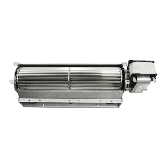
Model:
GFK4B Fan Kit
This fan kit has been tested for use with specific Hearth & Home Technologies fireplaces. Check with your local building
code agency before you begin installation to ensure compliance with local codes, including the need for permits and follow-
up inspections. If you encounter any problems regarding code approvals, or if you need clarification of any of the instruc-
tions contained here, contact your Hearth & Home Technologies dealer. For the dealer nearest you, please visit www.
hearthnhome.com.
The GFK4B Fan Kit has been designed to circulate room air through the appliance to enhance heat output. The fan kit oper-
ates on 120VAC, 60 Hz power. This is available through a receptacle in the factory installed junction box. The junction box
is located in the controls compartment of the appliance.
A control module is provided with the fan kit which automatically turns the fan on and off at preset times and is equipped with
a variable speed control to provide a quiet forced air flow at the desired speeds.
Check Contents of Shipping Carton
Compare contents of carton in Table 1 with the actual parts received. If any parts are missing or damaged, contact your
dealer before starting installation. Do not install a damaged fan kit.
Installation Precautions
The GFK4B Fan Kit is tested and safe when installed in accordance with this installation manual. It is your responsibility to
read all instructions before starting installation and to follow these instructions carefully during installation to assure maxi-
mum benefit from, and safe operation of, the fan.
WARNING
Shock Risk
Explosion Risk
Do NOT wire 110-120 VAC to gas control
valve.
Do NOT wire 110120 VAC to wall switch
•
Incorrect wiring will damage millivolt
values.
•
Incorrect wiring will override IPI safety
lockout and may cause explosion.
Note: This appliance must be electrically wired and grounded
in accordance with local codes or, in the absence of local
codes, with National Electric Code ANSI/NFPA 70-latest
edition or the Canadian Electric Code CSA C22.1.
CAUTION
Sharp Edges
•
Wear protective gloves and safety
glasses during installation.
Note: An arrow () found in the text signifies change in
content.
tm
Hearth & Home Technologies • GFK4B Fan Kit • 4016-095 Rev N • 04/21
WARNING
Shock Risk
Fire Risk
Use ONLY optional accessories approved
for this appliance.
•
Using non-listed accessories voids
warranty.
•
Using non-listed accessories may result
in a safety hazard.
•
Only Hearth & Home Technologies
approved accessories may be used
safely.
Part
Description
Number
Fan
19263A
Fan Bracket
4016-099
Electrical Cord
26648
Control Module
4021-708
Air Deflector
22520
Fastener Pack
4025-019
Magnetic Tape
4021-654
Screws
Foam Tape
4021-655
Wire Assembly
2005-863
Jumper Wire
(blue)
Table 1
Contents of Carton
Note: You may not need all parts included with this kit.
Installation
Instructions
Qty.
1
1
1
1
1
1
2
6
2
1
1
1
Advertisement

Related Manuals for Hearth and Home Technologies 19263A

Summary of Contents for Hearth and Home Technologies 19263A
- Page 1 Note: This appliance must be electrically wired and grounded Description Number Qty. in accordance with local codes or, in the absence of local 19263A codes, with National Electric Code ANSI/NFPA 70-latest Fan Bracket 4016-099 edition or the Canadian Electric Code CSA C22.1.
- Page 2 1. Install the Air Deflector • If the fan is being installed in a B-vent appliance, the fan shield supplied with the appliance will also need to be Open the bottom front panel by lifting and pulling it away attached. See Figure 4. from the appliance.
- Page 3 3. Install the Fan Position the fan all the way to the rear and center in the FIREBOX appliance. Press the fan (magnets to the bottom) to the BOTTOM back of the appliance. See Figure 7. Plug the fan cord into the fan receptacle labeled “FAN”...
- Page 4 • Dexen Valve (IPI) * (wiring diagram when using junction box with spade connectors) Connect the black, white and red wires with 1/4 in. female connectors from fan control module to appliance junction box as shown in Figure 10. Connect the black ground wire from the fan control module to the appliance. Remove the green ignition control wire from the valve.
- Page 5 • SIT Valve Connect the black, white and red wires with 1/4 in. female connectors from fan control module to appliance junction box as shown in Figure 12. Connect the black ground wire with the ring terminal to the TP screw on the valve (center). Connect blue jumper wire between fan control wire (black with white stripe) and valve.