
Related Manuals for Pilz PSSu E F 4DI


Summary of Contents for Pilz PSSu E F 4DI
- Page 1 PSSu E F 4DI(-T)(-R) Decentralised system PSSuniversal I/O Operating Manual-21310-EN-08...
- Page 2 Preface This document is a translation of the original document. All rights to this documentation are reserved by Pilz GmbH & Co. KG. Copies may be made for internal purposes. Suggestions and comments for improving this documentation will be gratefully received.
-
Page 3: Table Of Contents
Changing an electronic module during operation Section 6 Wiring General wiring guidelines 6.1.1 Mechanical connection of the base modules Terminal configuration Connecting the module Section 7 Operation Messages Display elements 7.2.1 Display elements for module diagnostics Operating Manual PSSu E F 4DI(-T)(-R), 21310-EN-08... - Page 4 Contents 7.2.2 Display elements for input status Section 8 Technical details Safety characteristic data Section 9 Order reference Product Accessories Operating Manual PSSu E F 4DI(-T)(-R), 21310-EN-08...
-
Page 5: Operating Manual Pssu E F 4Di(-T)(-R)
Introduction Validity of documentation This documentation is valid for the product types PSSu E F 4DI, PSSu E F 4DI-T and PSSu E F 4DI-R. It is valid until new documentation is published. This operating manual explains the function and operation, describes the installation and provides guidelines on how to connect the product. -
Page 6: Definition Of Symbols
It also highlights areas within the text that are of particular import- ance. INFORMATION This gives advice on applications and provides information on special fea- tures. Operating Manual PSSu E F 4DI(-T)(-R), 21310-EN-08... -
Page 7: Overview
Switch status of each input – Module error For failsafe applications in system environment A and B T-type: PSSu E F 4DI-T: for increased environmental requirements R-type: PSSu E F 4DI-R: for railway applications Operating Manual PSSu E F 4DI(-T)(-R), 21310-EN-08... -
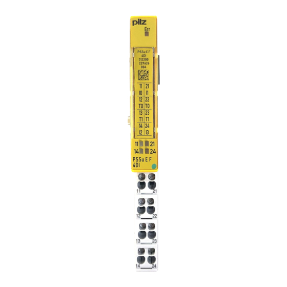
Page 8: Front View
2D code 3: Labelling strip for the terminal configuration on the base module 4: Status LEDs 5: Name of electronic module 6: Connection level 1 7: Connection level 2 8: Connection level 3 Operating Manual PSSu E F 4DI(-T)(-R), 21310-EN-08... - Page 9 11: Round connection holes (connection levels 1, 2, 3 and 4) for connecting the signal lines 12: Mounting slot for colour marker to label the connection level (connection levels 1, 2, 3 and 4) Operating Manual PSSu E F 4DI(-T)(-R), 21310-EN-08...
-
Page 10: Safety
The module may be used for failsafe applications in system environment A and B (automa- tion system PSS 4000). The modules PSSu E F 4DI and PSSu E F 4DI-T may be used as a safety components in accordance with the Lifts Directive 95/16/EC in accordance with the requirements of EN 81-1/2:1998+A3:2009, EN 81-20:2015, EN 81-50:2015, EN 81-22:2014 and... -
Page 11: Safety Regulations
Safety PSSu BP-C1 1/12 S PSSu BP-C1 1/12 C The PSSu E F 4DI-T and PSSu E F 4DI-R modules may be used in conjunction with the fol- lowing base modules: PSSu BP 1/8 S-T PSSu BP 1/8 C-T PSSu BP 1/12 S-T... -
Page 12: Function Description
Detection of shorts across contacts The test pulses are used to detect shorts between inputs. Shorts between inputs are detected when – the test pulses are different (test pulse 0, test pulse 1) or when Operating Manual PSSu E F 4DI(-T)(-R), 21310-EN-08... -
Page 13: Integrated Protection Mechanisms
(SafetyBUS p). The PSSu can be divided into sections A and B for this purpose. All the FS inputs on a PSSu always belong to section B. Section A and section B on a PSSu may belong to different I/O-Groups. Operating Manual PSSu E F 4DI(-T)(-R), 21310-EN-08... -
Page 14: Addresses In The Process Image
PSSu assignment in system environment B Data access is via pre-defined I/O data types: I/O data name I/O data type I/O data element Meaning I0(11), I1(21), I2(14), I3(24) FS_I_DI Data: SAFEBOOL Input data I0 ... I3 Operating Manual PSSu E F 4DI(-T)(-R), 21310-EN-08... -
Page 15: Installation
5.1.1 Dimensions Base modules with four connection levels: 12,6 mm 8,1 mm 52,1 mm (0.496") (0.319") (2.051") 12,6 mm 72,6 mm (0.496") (2.858") Operating Manual PSSu E F 4DI(-T)(-R), 21310-EN-08... -
Page 16: Installing The Base Module
Push the base module back [2] until you hear it lock into position. On the mounting rail, slide the base module to the left until you hear the two lateral mounting hooks on the adjacent module lock into position [3]. Operating Manual PSSu E F 4DI(-T)(-R), 21310-EN-08... -
Page 17: Inserting And Removing An Electronic Module
This is how the base module is coded. The mechanics of the electronic modules are designed for 50 plug in/out cycles. Operating Manual PSSu E F 4DI(-T)(-R), 21310-EN-08... -
Page 18: Inserting An Electronic Module
Installation 5.3.1 Inserting an electronic module Procedure: The electronic module must audibly lock into position [1]. Mark the electronic module using the labelling strips [2]. Schematic representation: Operating Manual PSSu E F 4DI(-T)(-R), 21310-EN-08... -
Page 19: Removing An Electronic Module
– The substitute values are used for the modules' FS outputs, with Valid Bits = FALSE. CAUTION! Sparking can cause interference and errors! Only change the module when the load is switched off! Operating Manual PSSu E F 4DI(-T)(-R), 21310-EN-08... -
Page 20: Wiring
Insert the screwdriver [4] into the square hole [1]. – Insert the stripped cable into the round fixing hole [2], as far as it will go [5]. – Pull out the screwdriver [6]. – Check that the cable is firmly seated. Operating Manual PSSu E F 4DI(-T)(-R), 21310-EN-08... - Page 21 To crimp the ferrules you can use crimp pliers (crimp form A or C) conforming to EN 60947-1, such as the PZ 1.5 or PZ 6.5 from Weidmüller, for example. – Maximum torque setting: 0.8 Nm Use copper wiring. Operating Manual PSSu E F 4DI(-T)(-R), 21310-EN-08...
-
Page 22: Terminal Configuration
+24 V output (periphery supply, 12-22 linked within the base module) 13 -23: Test pulse output T1 or +24 V output (periphery supply, 13-23 linked within the base module) 14: Input I2 24: Input I3 Operating Manual PSSu E F 4DI(-T)(-R), 21310-EN-08... - Page 23 14: Input I2 24: Input I3 15 -25: Test pulse output T1 or +24 V output (periphery supply, 15-25 linked within the base module) 16 -26: C-rail supply (13-23-16-26 linked within the base module) Operating Manual PSSu E F 4DI(-T)(-R), 21310-EN-08...
-
Page 24: Connecting The Module
+ 24 V Without test pulses (unchecked) Input device with homogeneous channels + 24 V + 24 V Without test pulses (unchecked) Input device with diverse channels + 24 V + 24 V Operating Manual PSSu E F 4DI(-T)(-R), 21310-EN-08... - Page 25 Wiring Input circuit Single-channel input device Dual-channel input device With test pulses (checked) With test pulses (checked) Input device with homogeneous channels With test pulses (checked) Input device with homogeneous channels Operating Manual PSSu E F 4DI(-T)(-R), 21310-EN-08...
- Page 26 Wiring Input circuit Single-channel input device Dual-channel input device With test pulses (checked) Input device with diverse channels Operating Manual PSSu E F 4DI(-T)(-R), 21310-EN-08...
-
Page 27: Operation
Change faulty module. Possible cause: Input defective. Test pulse error Possible causes: Short circuit Rectify the short circuit or change between a test pulse and a supply the faulty module. voltage, or a defective module. Operating Manual PSSu E F 4DI(-T)(-R), 21310-EN-08... -
Page 28: Display Elements
- - - 0 signal 13 23 (Input 2) 14 24 Green 1 signal - - - 0 signal (Input 3) Green 1 signal - - - 0 signal (Input 4) Green 1 signal Operating Manual PSSu E F 4DI(-T)(-R), 21310-EN-08... -
Page 29: Technical Details
Max. threshold voltage when signal changes from "0" to "1" 10 V 10 V 10 V Max. processing time of input when signal changes from "1" to "0" 1 ms 1 ms 1 ms Operating Manual PSSu E F 4DI(-T)(-R), 21310-EN-08... - Page 30 Climatic suitability EN 60068-2-1, EN EN 60068-2-1, EN 60068-2-14, EN 60068-2-14, EN EN 50125-1, EN 50125-3, 60068-2-2, EN 60068-2-2, EN EN 50155, EN 60068-2-1, 60068-2-30, EN 60068-2-30, EN EN 60068-2-14, EN 60068-2-78 60068-2-78 60068-2-2 Operating Manual PSSu E F 4DI(-T)(-R), 21310-EN-08...
- Page 31 Number of shocks Acceleration Duration 11 ms 11 ms 11 ms In accordance with the standard EN 60068-2-27 EN 60068-2-27 EN 61373 Number of shocks 1000 1000 Acceleration Duration 16 ms 16 ms 30 ms Operating Manual PSSu E F 4DI(-T)(-R), 21310-EN-08...
-
Page 32: Safety Characteristic Data
Where standards are undated, the 2009-10 latest editions shall apply. Safety characteristic data NOTICE You must comply with the safety-related characteristic data in order to achieve the required safety level for your plant/machine. Operating Manual PSSu E F 4DI(-T)(-R), 21310-EN-08... - Page 33 A safety function's SIL/PL values are not identical to the SIL/PL values of the units that are used and may be different. We recommend that you use the PAScal software tool to calculate the safety function's SIL/PL values. Operating Manual PSSu E F 4DI(-T)(-R), 21310-EN-08...
-
Page 34: Order Reference
PSSu BP-C1 1/12 S-T Base module with C-rail and screw terminals, T-type 314 622 PSSu BP-C1 1/12 C Base module with C-rail and cage clamp terminals 312 623 PSSu BP-C1 1/12 C-T Base module with C-rail and cage clamp terminals, T-type 314 623 Operating Manual PSSu E F 4DI(-T)(-R), 21310-EN-08... - Page 35 Front cover Support Technical support is available from Pilz round the clock. Americas Australia Scandinavia Brazil +61 3 95600621 +45 74436332 +55 11 97569-2804 Spain Canada Europe +34 938497433 +1 888-315-PILZ (315-7459) Austria Switzerland Mexico +43 1 7986263-0 +41 62 88979-30...