Advertisement
Quick Links
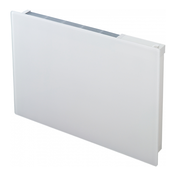
Girona Panel Heaters
Dimensions
(millimetres)
Model(s)
Watt
GFP050 W/B
0.5kW
GFP075 W/B
0.75kW
GFP100 W/B
1.0kW
GFP150 W/B
1.5kW
GFP200 W/B
2.0kW
IMPORTANT: THESE INSTRUCTIONS SHOULD BE READ CAREFULLY AND RETAINED FOR FUTURE REFERENCE
Important Safety Advice
When using electrical appliances, basic precautions
should always be followed to reduce the risk of fire,
electrical shock, and injury to persons, including the
following:
IIMPORTANT – The wall bracket supplied with the
appliance must be used.
WARNING - DO NOT USE THIS HEATER IN THE IMMEDIATE
SURROUNDINGS OF A BATH, A SHOWER OR A SWIMMING
POOL.
IMPORTANT – If the heater is installed in a room
containing a bath or shower, it must be so installed that
switches and other controls cannot be touched by a
person using a bath or shower.
Do not use outdoors.
Do not locate the heater immediately below a fixed socket
outlet or connection box.
Do not cover the heater. Do not place material or
garments on the heater, or obstruct the air circulation
around the heater, for instance by curtains or furniture,
as this could cause overheating and a fire risk.
NEVER cover or obstruct in any way the heat outlet slots
at the top of the heater or the air inlet slots in the base of
the heater.
The heater carries the Warning symbol indicating
that it must not be covered.
WARNING – THE SURFACES OF THIS HEATER CAN BE HOT.
Momentary contact with any part of the heater should
not cause injury.
This appliance is not intended for use by persons
(including children) with reduced physical, sensory or
mental capabilities, or lack of experience and
knowledge, unless they have been given supervision or
instruction concerning use of the appliance by a person
responsible for their safety. Children should be
supervised to ensure that they do not play with the
appliance.
Note that due care and consideration must be taken
when using this heater in series with a thermal control,
a program controller, a timer or any other device that
switches on the heat automatically, since a fire risk
exists when the heater is accidentally covered or
displaced.
If the supply cord is damaged, it must be replaced by a
special cord or assembly available from the
manufacturer or its service agent.
A
B
150
Min.
530
107
530
107
700
107
770
107
940
107
Installation and Operating Instructions
A
Electrical
WARNING – THIS APPLIANCE MUST BE EARTHED
The electrical installation must be carried out by a competent
electrician, and be in strict accordance with the current I.E.E.
regulations for Electrical Equipment in Buildings.
The wires in this mains lead are coloured in accordance
with the following code :
GREEN AND YELLOW :
BLUE :
BROWN :
BLACK :
- see also 'Pilot Wire Connection'.
The heater is fitted with a length of flexible cable type H05VV-
F size 4 x 1.0mm
2
for connection to the fixed wiring of the
premises through a suitable connection box positioned
adjacent to the heater.
A means for disconnection must be incorporated in the fixed
wiring of the premises in accordance with the wiring rules.
The supply circuit to the heater must incorporate a double
pole isolating switch having a contact separation of at least
3mm.
Pilot Wire Connection
The BLACK control wire is designed to carry a signal from
slot in or wall mounted Dimplex programmers. If, however a
programmer is not being used, the pilot wire should be
isolated in accordance with the current IEE Wiring
Regulations.
IMPORTANT - DO NOT connect the BLACK pilot wire to earth.
Care should be taken with the installation of the pilot wire(s)
as when switching to background (set back) they become
energised at 240V although only at a current of less than
100mA. In every case a suitable means of isolation must be
provided for the pilot wire and marked to indicate that two
sources of supply may be present at the heater.
Where pilot wires are installed separately from the heater
final sub-circuit they should be protected, double insulated
and carry their own integral earth continuity conductor.
Supplementary Earth Bonding
Should Equipotential Earth Bonding be required the earthing
conductor in the supply cord is deemed to provide the
supplementary bonding connection (see Regulation 547-
th
03-05, 17
Edition I.E.E. Wiring Regulations).
INDGUKP7RG Issue 2
shelf
300 Min.
B
565
150 Min.
EARTH
NEUTRAL
LIVE
PILOT WIRE
Fig. 1
Advertisement

Related Manuals for Dimplex GFP050


Summary of Contents for Dimplex GFP050
- Page 1 The BLACK control wire is designed to carry a signal from WARNING – THE SURFACES OF THIS HEATER CAN BE HOT. slot in or wall mounted Dimplex programmers. If, however a Momentary contact with any part of the heater should programmer is not being used, the pilot wire should be not cause injury.
- Page 2 General The heater is designed for wall mounting on the wall bracket supplied. It should only be operated when in the upright position - see Fig. 1. All models are splashproof to IPX4 standard and may be used in bathrooms, however not in the immediate vicinity of baths, showers, water connections, wash basins or swimming pools.
- Page 3 Notes to the Installer Safety - Overheat protection For your safety this appliance is fitted with a thermal cut-out. Test Mode In the event that the product overheats for some reason, the When the heater is connected via a pilot wire system, the cut-out prevents excessive temperatures on the product by cutting the power to the heater.
- Page 4 Southampton Hampshire. SO30 2DF Republic of Ireland Tel. 01 8424833 [c] Dimplex UK Limited All rights reserved. Material contained in this publication may not be reproduced in whole or in part, without prior permission in writing of Dimplex UK Limited.