natus neoBLUE Service Manual
Led phototherapy system
Hide thumbs
Also See for neoBLUE:
- Service manual (47 pages) ,
- User manual (23 pages) ,
- Manual for home use (9 pages)
Table of Contents
Advertisement
Advertisement
Chapters
Table of Contents

Related Manuals for natus neoBLUE


Summary of Contents for natus neoBLUE
- Page 1 Service Manual...
- Page 2 Bili-meter is a registered trademark of Olympic Medical. © 2006 Natus Medical Incorporated. All rights reserved. This manual may not be reprinted or copied in whole or in part without written consent from Natus Medical Inc. The content of this manual may change without notice.
-
Page 3: Table Of Contents
About this manual 1.1.1 Overview 1.1.2 Intended users 1.1.3 Manual conventions Product description Pictorial introduction to the neoBLUE system Before you start Contacting Natus Technical Support Routine Maintenance Procedures CHAPTER 2 Cleaning 2.1.1 Cleaning the light enclosure and accessories 2.1.2... - Page 4 4.6.3 Removing the rocker switches Parts and Specifications CHAPTER 5 How to order parts Parts in context Parts list Illustrations of major parts Accessory pack Specifications Technical Note on Photometers Appendix: Index neoBLUE® LED Phototherapy System Service Manual PN 051296...
- Page 5 TABLE 3-1 Troubleshooting Guide TABLE 4-1 Equipment TABLE 4-2 Equipment TABLE 5-1 Parts List for Natus neoBLUE system TABLE 5-2 Accessory Pack TABLE A-1 neoBLUE Light Intensity Output Conversion Chart Figures FIGURE 1-1 External, front view FIGURE 1-2 External, rear view...
- Page 6 FIGURE 5-1 Subplate and its attachments FIGURE 5-2 Enclosure and its attachments FIGURE 5-3 LED light panel (item #1) FIGURE 5-4 Enclosure (item #2) FIGURE 5-5 Subplate (item #3) FIGURE 5-6 LED light current assembly (item #4) neoBLUE® LED Phototherapy System Service Manual PN 051296...
-
Page 7: Introduction
Pictorial introduction to the neoBLUE system Before you start Contacting Natus Technical Support About this manual 1.1.1 Overview This manual contains information needed for servicing the neoBLUE Phototherapy System. • Description of the product and overview illustrations (Chapter 1) • Troubleshooting guide (Chapter 2) •... -
Page 8: Intended Users
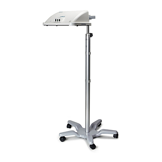
Parts List (Chapter 5) is used to identify the part. Product description The neoBLUE LED Phototherapy System consists of two products – the neoBLUE Phototherapy light source (light) and the neoBLUE Phototherapy Roll Stand (roll stand). neoBLUE® LED Phototherapy System Service Manual... -
Page 9: Pictorial Introduction To The Neoblue System
Pictorial introduction to the neoBLUE system This section is meant to acquaint you with the various views of the neoBLUE light that you will see in the course of troubleshooting and repairing it. The item numbers and names used in the Parts List (see Chapter 5) are used throughout the book whenever parts are discussed. -
Page 10: Figure 1-1 External, Front View
Light intensity rocker switch Sets intensity to high or low Target light rocker switch Controls red target light. Momentary action. Calibration access cover Covers potentiometers for adjusting light intensity Self tapping screw Screw, 5/8” neoBLUE® LED Phototherapy System Service Manual PN 051296... -
Page 11: Figure 1-2 External, Rear View
Pictorial introduction to the neoBLUE system External, rear view FIGURE 1-2 Item Description Notes Enclosure Diffuser Diffuses the light from the LEDs AC power entry module Includes on/off switch (I/0); fuses Enclosure fan filter assembly Consists of a cover, filter, and backplate... -
Page 12: Figure 1-3 Internal, View From Top
LED light panel Subplate Holds power supply, assembly, and subplate fan LED light current assembly Power supply Diffuser Diffuses the light from the LEDs AC power entry module Includes on/off switch (1/0); fuses neoBLUE® LED Phototherapy System Service Manual PN 051296... - Page 13 Pictorial introduction to the neoBLUE system Item Description (Continued) Notes light intensity rocker switch For selecting intensity level Target light rocker switch Indicates center of treatment area Enclosure fan Cools the enclosure Vent guard Subplate fan Cools the LED light panel and diffuser...
- Page 14 LED light current assembly FIGURE 1-5 LED light panel header, J1 Main power, fan header, J2 Front panel switch header, J3 Light intensity adjustment potentiometers The block diagram, Figure 1-6, lays out the electrical connections. neoBLUE® LED Phototherapy System Service Manual PN 051296...
-
Page 15: Figure 1-6 Block Diagram
Pictorial introduction to the neoBLUE system Block diagram FIGURE 1-6 neoBLUE® LED Phototherapy System Service Manual PN 051296... -
Page 16: Before You Start
Contacting Natus Technical Support Should you encounter situations that are not covered by this Service Manual, contact a Natus Technical Support representative. Please have your Natus device model and serial number available when calling Technical Support. -
Page 17: Routine Maintenance Procedures
Routine Maintenance CHAPTER 2 Procedures This chapter includes procedures for routine maintenance of the neoBLUE light, hereafter called the Unit Under Test (UUT). Cleaning Safety testing Performance Verification Adjusting light intensity These procedures must be performed after any of the following events and/or as prescribed by the institution’s maintenance schedule:... -
Page 18: Cleaning The Light Enclosure And Accessories
The air filter should be cleaned at least every 30 days to prevent possible instrument overheating. Remove the cover from the enclosure fan filter assembly, shown below in Figure 2-1. Locating the filter FIGURE 2-1 neoBLUE® LED Phototherapy System Service Manual PN 051296... -
Page 19: Safety Testing
UL 2601-1 ANSI/NFPA 99 500 μA 300 μA Normal Closed Closed 500 μA 300 μA Reversed Closed Closed 1000 μA 500 μA Normal Open Closed 1000 μA 500 μA Normal Closed Open neoBLUE® LED Phototherapy System Service Manual PN 051296... -
Page 20: Performance Verification
Ohmeda BiliBlanket® Meter II or equivalent (see Note below) Potentiometer adjustment tool GC Electronics 8608 or small flat head screwdriver Allen wrench 5/16” 90 degree or equivalent Safety glasses Amber Work pad Any non-abrasive non-static surface neoBLUE® LED Phototherapy System Service Manual PN 051296... -
Page 21: Verifying General Performance
Note: If a different photometer is used please refer to the "Technical Note on Photometers" on page 55. If the meter is not listed in the conversion chart, please contact Natus Technical Service before adjusting the LED light panel intensity. -
Page 22: Checking The Light Intensity
( ) as shown in Figure 2-2. Check the intensity on the HIGH setting: • Place the light intensity rocker switch (8) in the HIGH position. neoBLUE® LED Phototherapy System Service Manual PN 051296... - Page 23 UUT can be returned to the user. Turn off the UUT and ignore all further steps in this chapter. If light intensity on either setting was not within tolerance, leave the test setup as is and proceed to Section 2.4. neoBLUE® LED Phototherapy System Service Manual PN 051296...
-
Page 24: Adjusting Light Intensity
If necessary, use the adjustment tool to adjust potentiometer B for a light intensity of 12-15μW/cm /nm. If the tolerances in steps 4 and 5 in Section 2.3.2 are met, replace the calibration access cover. The UUT can be returned to the user. neoBLUE® LED Phototherapy System Service Manual PN 051296... -
Page 25: Troubleshooting The Neoblue Light Troubleshooting The Led Light Current Assembly
Troubleshooting Guide CHAPTER 3 This chapter assumes that you are a qualified biomedical technician who is familar with the neoBLUE light as described in Chapter 1. Troubleshooting the neoBLUE light Troubleshooting the LED light current assembly Troubleshooting the neoBLUE light... -
Page 26: Light Intensity Will Not Adjust
Figure 2-3 on reached mum trim position of the intensity adjustment page 22 potentiometer. If you still cannot achieve the desired intensity, Section 4.2 on replace the LED light panel. page 32 neoBLUE® LED Phototherapy System Service Manual PN 051296... -
Page 27: Light Intensity Will Not Change Between High And Low
Perform an end to end continuity check on the power/fan cable No power Verify with a DVM that there is 24-26.5V Figure 1-5 on between pins 1 and 4 of J2. page 12 neoBLUE® LED Phototherapy System Service Manual PN 051296... -
Page 28: Figure 1-4 Power Supply
If any of the tests below fail, you have a damaged board and need to replace it. Visually inspect for any burnt, broken, or shorted components. Check for power (24-26.5VDC) at the following pin locations: • J1 pins 1,2,3 • U1 pin 4 neoBLUE® LED Phototherapy System Service Manual PN 051296... - Page 29 R3 (High) and R6 (Low) are turned. Turning clockwise should decrease the voltage. Conversely turning counterclockwise should increase the voltage. Function Pins Voltage range Blue LEDs U1 pin 7 1.5-0.5 VDC (HIGH setting) 0.85-0.17 VDC (LOW setting) neoBLUE® LED Phototherapy System Service Manual PN 051296...
- Page 30 Chapter 3 Troubleshooting Guide neoBLUE® LED Phototherapy System Service Manual PN 051296...
-
Page 31: Repair Procedures
Repair procedures CHAPTER 4 This chapter presents procedures for repairing the neoBLUE light, hereafter call the UUR (Unit Under Repair). Only qualified personnel should open the enclosure, remove and/or replace components or make adjustments. If your medical facility does not have qualified per- sonnel, please contact Natus Technical Service for further assistance. -
Page 32: Removing The Light Diffuser
CAUTION: Approved anti-static measures must be used anytime the UUR is disassembled. Removing the light diffuser Detach the UUR from its roll stand. Place the UUR upside-down on a suitable work pad. neoBLUE® LED Phototherapy System Service Manual PN 051296... -
Page 33: Figure 4-1 Removing The Diffuser
The diffuser must be screwed in securely. Failing to secure the diffuser could cause injury to the patient if the diffuser itself or any internal components were to become loose and fall during therapy. neoBLUE® LED Phototherapy System Service Manual PN 051296... -
Page 34: Removing The Led Light Panel
(B) or under the outside board edge. Repeat the process until all six fasteners are released. Then carefully lift the edge of the board using the Allen wrench until the board can be removed from the subplate. neoBLUE® LED Phototherapy System Service Manual PN 051296... -
Page 35: Removing The Subplate
Note: There are six lock fasteners around the periphery of the subplate and many open slots on the subplate. Release the lock fasteners by depressing the protruding latch into the post while gently pulling the subplate away from the enclosure. neoBLUE® LED Phototherapy System Service Manual PN 051296... -
Page 36: Figure 4-3 Detaching The Subplate
LED light panel by reversing the steps in Section 4.2 on page 32. Then return to Chapter 3. If you are replacing the subplate: • First remove all components (Section 4.4). neoBLUE® LED Phototherapy System Service Manual PN 051296... -
Page 37: Removing Components From The Subplate
Removing the power supply assembly (Section 4.4.1) • Removing the LED light current assembly (Section 4.4.2) • Removing the subplate fan assembly (Section 4.4.3) • Removing the LED light panel cable (Section 4.4.4) neoBLUE® LED Phototherapy System Service Manual PN 051296... -
Page 38: Removing The Power Supply Assembly
Then reverse all steps in Section 4.3 until the UUR is completely assembled. • Return to Chapter 2 and perform the safety tests and performance verification and adjustment. If the subplate is being replaced continue to Section 4.4.2. neoBLUE® LED Phototherapy System Service Manual PN 051296... -
Page 39: Removing The Led Light Current Assembly
Disconnect all cable connectors from their receptacles observing orientation and cable colors. Use the wire cutters to remove the two tie-wraps securing the cable to the subplate and remove the the cable. neoBLUE® LED Phototherapy System Service Manual PN 051296... -
Page 40: Replacing The Subplate
Removing the AC power entry module (Section 4.6.2) • Removing the rocker switches (Section 4.6.3) Equipment TABLE 4-2 Tools required Type Screwdriver Phillips, medium Hex driver 5/16" deep socket Hex driver 1/4" deep socket neoBLUE® LED Phototherapy System Service Manual PN 051296... -
Page 41: Removing The Enclosure Fan
Obtain the replacement and reverse these steps to install. • Reverse all steps in Section 4.3 until the UUR is completely assembled. • Return to Chapter 2 and perform the safety tests and performance verification and adjustment. neoBLUE® LED Phototherapy System Service Manual PN 051296... -
Page 42: Removing The Ac Power Entry Module
Obtain the replacement and reverse these steps to install. • Reverse all steps in Section 4.3 until the UUR is completely assembled. • Return to Chapter 2 and perform the safety tests and performance verification and adjustment. neoBLUE® LED Phototherapy System Service Manual PN 051296... -
Page 43: Parts And Specifications
Call Technical Service at 1-888-496-2887 to order parts or for general technical information. A minimum order may be required for spare parts. The list of product specifications in this chapter will guide you in making purchases from ven- dors other than Natus. neoBLUE® LED Phototherapy System Service Manual PN 051296... -
Page 44: Parts In Context
Chapter 5 Parts and Specifications Parts in context Two views of the neoBLUE light appear below, to show you where the parts are and how they fit together. The views are: • Subplate and its attachments. The subplate holds the power supply, subplate fan, and LED light current assembly •... -
Page 45: Figure 1-5 Led Light Current Assembly
27 (x5) 27 (x4) 19 (x4) 31 (x3) Item Description Item Description Subplate Screw 1/4” LED light current assembly Nut 5/16” Power supply Nylon board lock fasteners Subplate fan Screw 1 1/4” neoBLUE® LED Phototherapy System Service Manual PN 051296... -
Page 46: Figure 5-2 Enclosure And Its Attachments
AC power entry module Nut, 5/16” light intensity Screw, 1 3/4” Target rocker switch Screw, 5/8” Fan, external Vent guard Reverse lock fastener Enclosure fan filter assembly Thumbscrew Calibration access cover Locating post screw neoBLUE® LED Phototherapy System Service Manual PN 051296... -
Page 47: Parts List
The column headings in the parts list table are: Item # Number used to refer to the part in this manual Quantity of this part used in the neoBLUE light Part # Natus part number, for ordering the part Name... -
Page 48: Parts List For Natus Neoblue System
Chapter 5 Parts and Specifications Parts List for Natus neoBLUE system TABLE 5-1 Item# Part # Name Illustration 600123 Rocker switch, target light 040772 Fan, enclosure 600131 Vent guard 600126 Enclosure fan filter assembly 030646 Calibration access cover neoBLUE® LED Phototherapy System Service Manual... - Page 49 Parts list Parts List for Natus neoBLUE system TABLE 5-1 Item# Part # Name Illustration 040773 Fan, subplate 030707 Cable, Intensity/target 5 conductor cable w/ 1 connector and 5 spade connectors. 030708 Cable, Fan/power supply 4 Conductor cable w/2 connectors...
- Page 50 Chapter 5 Parts and Specifications Parts List for Natus neoBLUE system TABLE 5-1 Item# Part # Name Illustration 800043 Screw, 4-40x5/8” 800008 Nut, 4-40 800221 Fastener, Reverse lock 800228 Fastener, Nylon board lock 800230 Rubber foot, attached to diffuser 800226 Thumbscrew, 8-32 neoBLUE®...
- Page 51 Parts list Parts List for Natus neoBLUE system TABLE 5-1 Item# Part # Name Illustration 800227 Screw, Locating post 800050 Screw, 6-32x1 1/4” 040757 Accessory pack Section 5.5 on page 51 neoBLUE® LED Phototherapy System Service Manual PN 051296...
-
Page 52: Illustrations Of Major Parts
Illustrations of major parts LED light panel (item #1) FIGURE 5-3 27 (x4) Connector for LED cable Nylon board lock fastener Enclosure (item #2) FIGURE 5-4 26 (x6) Roll stand mounting plate Reverse lock fastener neoBLUE® LED Phototherapy System Service Manual PN 051296... -
Page 53: Accessory Pack
Nylon board lock fasterner Accessory pack The accessory pack included with your neoBLUE light includes spare parts and information. Its contents are listed in Table 5-2 on page 52. The CD Rom in the accessory pack contains the follow- ing files: •... - Page 54 CD Rom Power Cord, Hospital Grade Power cord strain relief Thumbscrew, 8-32 Screw, Locating post Enclosure filter set, 5 filters Cable, Intensity/target 5 conductor cable w/ 1 connector and 5 spade connectors. neoBLUE® LED Phototherapy System Service Manual PN 051296...
-
Page 55: Specifications
< 100 μA Leakage current Audible Noise <60 dB Dimensions Maximum Height < 6 ft (1.83 m) Weight < 8.0 lbs (3.6 kg) (light enclosure only) < 40 lbs (18 kg) (with roll stand) neoBLUE® LED Phototherapy System Service Manual PN 051296... - Page 56 0º (horizontal) to approx. 40º Clearance of base from floor <4 inches (10 cm) Base 5 legs with casters (2 locking casters) Regulatory Standards Type BF EN 60601-1-1, EN60601-1-2 EN60601-2-50 UL2601-1 CSA C22.2 606.1 neoBLUE® LED Phototherapy System Service Manual PN 051296...
-
Page 57: Technical Note On Photometers
(typically on an annual basis). The light intensity output of the neoBLUE device is measured at Natus (prior to shipment) with the Ohmeda BiliBlanket® Meter II. Because your facility may use a different photometer to measure the light intensity output, it is necessary to understand how your reading correlates to the Ohmeda reading. -
Page 58: Neoblue Light Intensity Output Conversion Chart
+/- 3% +/- 2% +/- 1.9% * This photometer is used for measuring the neoBLUE light intensity output prior to shipment. If necessary, please call Natus Medical Technical Service at +1 650.802.0400 or your autho- rized service representative. neoBLUE® LED Phototherapy System Service Manual... -
Page 59: Index
33, 34, 39, 47 calibration all attachments access cover illus. See "light intensity" cleaning cautions components definition illus. cleaning removing enclosure front view neoBLUE® LED Phototherapy System Service Manual PN 051296... - Page 60 9, 10 J1, J2, J3 part numbers in manual leakage See "LED light current assembly" 17, 53 LED light current assembly photometers damaged conversion chart illus. different brands removing using neoBLUE® LED Phototherapy System Service Manual PN 051296...
- Page 61 See "roll stand" yellow lights standards 17, 54 subplate all attachments illus. components, illus. components, removing removing illus. replacing subplate fan removing switches light intensity on/off target light neoBLUE® LED Phototherapy System Service Manual PN 051296...
- Page 62 Index neoBLUE® LED Phototherapy System Service Manual PN 051296...