natus neoBLUE Service Manual
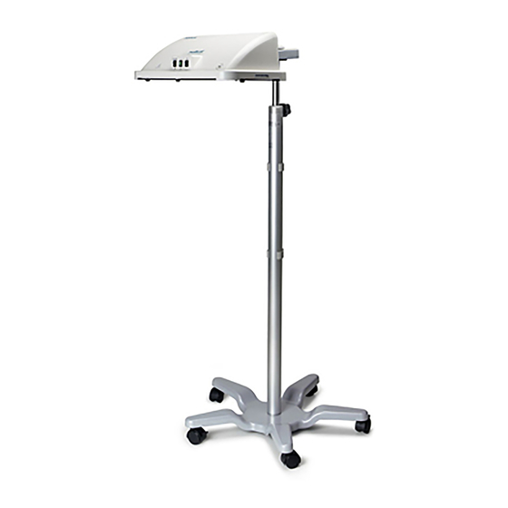
Led phototherapy system
Hide thumbs
Also See for neoBLUE:
- Service manual (62 pages) ,
- User manual (23 pages) ,
- Manual for home use (9 pages)
Table of Contents
Advertisement
Advertisement
Table of Contents
Troubleshooting

Related Manuals for natus neoBLUE


Summary of Contents for natus neoBLUE
- Page 1 Service Manual...
- Page 2 Joey is a registered trademark of Philips Healthcare. © 2015 Natus Medical Incorporated. All rights reserved. This manual may not be reprinted or copied in whole or in part without written consent from Natus Medical Incorporated. The content of this manual may change without notice.
-
Page 3: Table Of Contents
5.2 Parts in context 5.3 Parts list 5.4 Illustrations of major parts 5.5 Accessory pack 5.6 Specifications Chapter 6 Measuring the neoBLUE light with a radiometer Chapter 7 Electromagnetic Specifications ® neoBLUE LED Phototherapy System Service Manual PN 001320 Rev K... -
Page 4: List Of Figures
Figure 5-1 Enclosure and its attachments Figure 5-2 Enclosure and its attachments Figure 5-3 LED light panel (item # 1) Figure 5-4 Enclosure (item # 2) Figure 5-5 LED light current assembly (item # 3) neoBLUE LED Phototherapy System Service Manual PN 001320 Rev K... -
Page 5: Chapter 1 Introduction
Contacting Natus Technical Support 1.1 About this manual 1.1.1 Overview This manual contains information needed for servicing the neoBLUE Phototherapy System. • Description of the product and overview illustrations (Chapter 1) • Maintenance procedures (Chapter 2) • Troubleshooting guide (Chapter 3) •... - Page 6 Throughout the manual, when parts are referred to in figures or in the text, the Item Number from the Parts List (Chapter 5) is used to identify the part. neoBLUE LED Phototherapy System Service Manual PN 001320 Rev K...
-
Page 7: Product Description
1.3 Pictorial introduction to the neoBLUE system This section is meant to acquaint you with the various views of the neoBLUE light that you will see in the course of troubleshooting and repairing it. The item numbers and names used in the Parts List (see Chapter 5) are used throughout the book whenever parts are discussed. -
Page 8: Figure 1-1 External, Front View
Sets intensity to high or low Target light rocker switch Controls red target light; momentary action On/standby switch Lights up when device is on 1-2 E IGURE XTERNAL REAR VIEW neoBLUE LED Phototherapy System Service Manual PN 001320 Rev K... - Page 9 Includes fuses Enclosure fan filter assembly Consists of a cover, filter, and backplate Thumbscrew For attaching enclosure to roll stand Locating post screw Slotted Timer Counts hours device is on ® neoBLUE LED Phototherapy System Service Manual PN 001320 Rev K...
-
Page 10: Figure 1-3 Internal, View From Top
Indicates center of treatment area Vent Guard Mounting plate Mounts light to roll stand On/standby switch Lights up when device is on Timer Counts the hours the device is on neoBLUE LED Phototherapy System Service Manual PN 001320 Rev K... -
Page 11: Figure 1-4 Power Supply
1-4 P IGURE OWER SUPPLY Item Description 24 volt ground Pins 5-8 24 volts + Pins 1-4 AC inlet ® neoBLUE LED Phototherapy System Service Manual PN 001320 Rev K... -
Page 12: Figure 1-5 Led Light Current Assembly
LED light panel header, J8 Main power, fan header, J2 Front panel switch header, J3 Light intensity adjustment potentiometers On/standby header, J4 Timer power header, J5 Fan power header, J6 Timer reset header, J7 neoBLUE LED Phototherapy System Service Manual PN 001320 Rev K... -
Page 13: Before You Start
The block diagram, Figure 1-6, lays out the electrical connections. 1-6 B IGURE LOCK DIAGRAM 1.4 Before you start WARNING Observe Electrostatic Discharge (ESD) precautions when handling, adjusting, or performing any procedure with the device internal components. ® neoBLUE LED Phototherapy System Service Manual PN 001320 Rev K... -
Page 14: Contacting Natus Technical Support
Chapter 1 Introduction 1.5 Contacting Natus Technical Support Should you encounter situations that are not covered by this Service Manual, contact a Natus Technical Support representative. Please have your Natus device model and serial number available when calling Technical Support. -
Page 15: Chapter 2 Routine Maintenance Procedures
Performance Verification Adjusting light intensity This chapter includes procedures for routine maintenance of the neoBLUE light, hereafter called the Unit Under Test (UUT). These procedures must be performed after any of the following events and/or as prescribed by the institution’s maintenance schedule: •... -
Page 16: Cleaning
Inspect filters for damage. If damaged, they must be replaced. Clean the filter by holding it under warm running water to clean away dust and other foreign materials. 2-1 L IGURE OCATING THE TWO FILTERS ON BACKSIDE OF ENCLOSURE neoBLUE LED Phototherapy System Service Manual PN 001320 Rev K... -
Page 17: Safety Testing
Closed Closed 100 µA Normal Closed Open 500 µA Normal Open Closed 100 µA Reversed Closed Open 500 µA Reversed Open Closed 500 µA Reversed Closed Open 500 µA ® neoBLUE LED Phototherapy System Service Manual PN 001320 Rev K... -
Page 18: Performance Verification
Note: If a different radiometer is used, please refer to the Conversion Chart in chapter If the meter is not listed, please contact Natus Technical Service before adjusting light intensity.. 2.3.1 Verifying general performance Turn off the Illuminated On/Standby switch and disconnect the AC power cord. - Page 19 Because your facility may use a different radiometer to measure the light intensity output, it is necessary to understand how your reading may differ from the neoBLUE Radiometer reading. Please refer to the Conversion Chart in chapter 6 for information on other meters.
-
Page 20: Figure 2-2 Measuring Distance
Determine the distance (B), which corresponds to how far the LED light panel will be from the patient during therapy. ® Important! The light intensity was factory calibrated with the neoBLUE Radiometer and was based off the distance (B) of 12 inches (30.5 cm). -
Page 21: Adjusting Light Intensity
If necessary, use the adjustment tool to adjust potentiometer B for a light intensity of 15 ± 2 µW/cm /nm. If the tolerances in steps 4 and 5 in Section 2.3.2 are met, the UUT can be returned to the user. ® neoBLUE LED Phototherapy System Service Manual PN 001320 Rev K... -
Page 22: Chapter 3 Troubleshooting Guide
In this chapter: Troubleshooting the neoBLUE light Troubleshooting the LED light current assembly This chapter assumes that you are a qualified biomedical technician who is familiar with the neoBLUE light. 3.1 Troubleshooting the neoBLUE light When opening the device, be sure to follow the procedures described in Chapter 4, as well as the steps and precautions in Section 2.2 on page 15 and Section 2.3 on page 16. - Page 23 If you still cannot achieve the desired Section 4.2 on intensity, replace the LED light panel. page 29 Broken switch Open device and verify intensity switch Light intensity will continuity using a DVM not change ® neoBLUE LED Phototherapy System Service Manual PN 001320 Rev K...
- Page 24 LED short or open You can increase the intensity if necessary. Section 2.4 on page 19 If the device still produces enough light there is no need to replace the panel. neoBLUE LED Phototherapy System Service Manual PN 001320 Rev K...
-
Page 25: Troubleshooting The Led Light Current Assembly
3.2 Troubleshooting the LED light current assembly Note: The tests in this section are intended as a guide to trouble shooting a neoBlue that has the appearance of not operating at optimum level. Successfully passing the tests of this section is not intended to indicate an acceptable operational level of the neoBLUE. - Page 26 Failure of this check indicates a possible problem with: 1. The Constant Current PCBA 2. The cable between the Constant Current PCBA and the LED PCBA 3. The LED PCBA. neoBLUE LED Phototherapy System Service Manual PN 001320 Rev K...
- Page 27 J4.1(+), J4.4(-) 21.5-24.5 VDC J4.2(+), J4.4(-) 0.0-0.1 VDC J4.3(+), J4.4(-) 0.0-0.1 VDC J5.1(+), J5.3(-) 0.0-0.1 VDC Failure of any of these checks indicates a possible Constant Current PCBA problem. ® neoBLUE LED Phototherapy System Service Manual PN 001320 Rev K...
-
Page 28: Chapter 4 Repair Procedures
Removing the LED light panel Removing components from the enclosure This chapter presents procedures for repairing the neoBLUE light, hereafter called the UUR (Unit Under Repair). Only qualified personnel should open the enclosure, remove and/or replace components or make adjustments. If your medical facility does not have qualified personnel, please contact Natus Technical Service for further assistance. -
Page 29: Removing The Lens
15) and Performance Verification (Section 2.3 on page 16). If further disassembly is required, store the lens in a protected area and proceed to Removing the LED light panel. ® neoBLUE LED Phototherapy System Service Manual PN 001320 Rev K... -
Page 30: Removing The Led Light Panel
If no further repair is required, reverse all previous steps in this procedure. Then return to Chapter 2 and perform safety and performance verification and adjustment. If further disassembly is required store the LED light panel in a safe anti-static environment. neoBLUE LED Phototherapy System Service Manual PN 001320 Rev K... -
Page 31: Removing Components From The Enclosure
Removing the switches on page 31 • Removing the timer on page 31 4-2 E ABLE QUIPMENT Tools required Type Screwdriver Phillips, medium Hex driver 5/16" deep socket Hex driver 1/4" deep socket ® neoBLUE LED Phototherapy System Service Manual PN 001320 Rev K... - Page 32 Remove the AC power entry module grounding cable to the mounting plate. Remove the two screws securing the AC power entry module from the enclosure and remove the module. neoBLUE LED Phototherapy System Service Manual PN 001320 Rev K...
- Page 33 Return to Chapter 2 and perform the safety tests and performance verification and adjustment. • Reverse all steps in Section 4.2 on page 28 until the UUR is completely assembled. ® neoBLUE LED Phototherapy System Service Manual PN 001320 Rev K...
-
Page 34: Chapter 5 Parts And Specifications
The list of product specifications in this chapter will guide you in making purchases from vendors other than Natus. 5.2 Parts in context Two views of the neoBLUE light appear below, to show you where the parts are and how they fit together. The views are: •... -
Page 35: Figure 5-1 Enclosure And Its Attachments
5-1 E IGURE NCLOSURE AND ITS ATTACHMENTS 19(x4) 19(x4) Item Description Screw 1/4” LED light current assembly Power supply Enclosure fan, Constant Current Board Side Enclosure fan, Power Supply Side ® neoBLUE LED Phototherapy System Service Manual PN 001320 Rev K... -
Page 36: Figure 5-2 Enclosure And Its Attachments
Screw, 1 3/4” Target rocker switch Screw, 5/8” Fan Enclosure, Power Supply Thumbscrew side Vent guard Locating post screw Enclosure fan filter assembly Illuminated on/standby switch Fan Enclosure, CCB side Timer neoBLUE LED Phototherapy System Service Manual PN 001320 Rev K... -
Page 37: Parts List
The column headings in the parts list table are: Item # Number used to refer to the part in this manual Quantity of this part used in the neoBLUE light Part # Natus part number, for ordering the part Name... - Page 38 10 Conductor cable w/ 2 connectors 800004 Screw, 6-32x 1/4” 014898 Screw, 8-32x1/4” 800232 Nut, 6-32x 5/16” 920164 Screw, 6-32x 1 3/4” 800043 Screw, 4-40x5/8” 800008 Nut, 4-40 001267 Rubber foot neoBLUE LED Phototherapy System Service Manual PN 001320 Rev K...
-
Page 39: Illustrations Of Major Parts
Cable, On/standby switch, 4 conductors with 1 connector and 4 spade connectors 5.4 Illustrations of major parts 5-3 LED # 1) IGURE LIGHT PANEL ITEM Connector for LED cable ® neoBLUE LED Phototherapy System Service Manual PN 001320 Rev K... -
Page 40: Figure 5-4 Enclosure (Item # 2)
Chapter 5 Parts and Specifications 5-4 E # 2) IGURE NCLOSURE ITEM Timer hole Roll stand mounting plate Illuminated switch hole 5-5 LED # 3) IGURE LIGHT CURRENT ASSEMBLY ITEM neoBLUE LED Phototherapy System Service Manual PN 001320 Rev K... -
Page 41: Accessory Pack
5.5 Accessory pack The accessory pack included with your neoBLUE light includes spare parts and information. Its contents are listed in Table 5-2. The CD Rom in the accessory pack contains the following files: • PDF files for the User Manual and this Service Manual. These manuals may be used online or printed out. -
Page 42: Specifications
LED PHOTOTHERAPY EQUIPMENT WITH RESPECT TO ELECTRICAL SHOCK, FIRE AND MECHANICAL HAZARDS ONLY IN ACCORDANCE WITH ANSI/AAMI ES60601-1 (2005), CAN/CSA-C22.2 NO. 60601-1 (2008), IEC 60601-2-50, UL 60601-1, AND CSA C22.2 No. 601.1-M90. neoBLUE LED Phototherapy System Service Manual PN 001320 Rev K... -
Page 43: Chapter 6 Measuring The Neoblue Light With A Radiometer
The intensity of the light is inversely related to the distance from the source. The light output can be adjusted using the two potentiometers (located on the side of the light enclosure) to accommodate different distances. Please refer to Section 2.4, Adjusting Light Intensity to adjust the neoBLUE light to the desired intensity when changing the distance. -
Page 44: Chapter 7 Electromagnetic Specifications
The neoBLUE LED Phototherapy device is intended for use in the electromagnetic environment ® specified below. The customer or the user of the neoBLUE LED Phototherapy device should assure that it is used in such an environment. Table 7.1 Electromagnetic emissions... - Page 45 UT) for 25 cycles in UT) for 25 cycles ® recommended that the neoBLUE input lines <5% UT (>95% dip <5% UT (>95% dip LED Phototherapy device be powered IEC 61000-4-11...
- Page 46 LED Phototherapy device is intended for use in an electromagnetic environment in which ® radiated RF disturbances are controlled. The customer or the user of the neoBLUE LED Phototherapy device can help prevent electromagnetic interference by maintaining a minimum distance between ®...
- Page 47 • At 80 MHz and 800 MHz, the separation distance for the higher frequency range applies. • These guidelines may not apply in all situations. Electromagnetic propagation is affected by absorption and reflection from structures, objects, and people. ® neoBLUE LED Phototherapy System Service Manual PN 001320 Rev K...