Acer TravelMate 4200 Series Service Manual
Hide thumbs
Also See for TravelMate 4200 Series:
- User manual (76 pages) ,
- Service manual (110 pages) ,
- Manual do utilizador (110 pages)
Table of Contents
Advertisement
Quick Links
Download this manual
See also:
User Manual
Advertisement
Table of Contents

Related Manuals for Acer TravelMate 4200 Series


Summary of Contents for Acer TravelMate 4200 Series
- Page 1 TravelMate 4200 Series Service Guide Service guide files and updates are available on the ACER/CSD web; for more information, please refer to http://csd.acer.com.tw PRINTED IN TAIWAN...
-
Page 2: Revision History
Revision History Please refer to the table below for the updates made on TravelMate 4200 service guide. Date Chapter Updates... - Page 3 Copyright Copyright © 2005 by Acer Incorporated. All rights reserved. No part of this publication may be reproduced, transmitted, transcribed, stored in a retrieval system, or translated into any language or computer language, in any form or by any means, electronic, mechanical, magnetic, optical, chemical, manual or otherwise, without the prior written permission of Acer Incorporated.
- Page 4 Conventions The following conventions are used in this manual: SCREEN MESSAGES NOTE WARNING CAUTION IMPORTANT Denotes actual messages that appear on screen. Gives bits and pieces of additional information related to the current topic. Alerts you to any damage that might result from doing or not doing specific actions.
- Page 5 DIFFERENT part number code to those given in the FRU list of this printed Service Guide. You MUST use the list provided by your regional Acer office to order FRU parts for repair and service of customer machines.
-
Page 7: System Specifications
256/512 MB of DDR2 533/677 MHz memory, upgradeable to 2 GB using two so DIMM modules (dual-channel support ) Display and graphics 15.4” WXGA color TFT LCD, 1280 x 800 pixel resolution, supporting simultaneous multi-window viewing via Acer DridVista 15” XGA color TFT LCD, 1024x 768 pixel resolution ® NVIDIA GeForce ®... - Page 8 5 C to 35 C Non-operating: -20 C to 65 C Humidity (non-condensing): operating: 20%~80% Non-operating: 20%~80% and MS Sound compatible ® PRO/Wireless 3945ABG network connection (dual-band tri-mode solution, supporting Acer SignalUp ® 2.0+EDR ° ° ° wireless technology Chapter 1...
-
Page 9: System Block Diagram
System Block Diagram This is for UMA models Fan Control DVI-D Conn. LCD Conn. page 17 page 15 L VDS CH7307C page 17 3.3V 33 MHz IDSEL:AD16 IDSEL:AD18 IDSEL:AD17 (PIRQE#, (PIRQG/H#, (PIRQF#, GNT#2, GNT#3, GNT#3, REQ#2) REQ#3) REQ#3) IEEE 1394 Mini PCI LAN (10/100) socket... -
Page 10: Board Layout
Board Layout Top View LCD Connector Lid Switch MDC Connector Power Button Connector Media Board Connector Touchpad Board Connector JP43 SIM Card Connector Touchpad Right Button Touchpad Left Button Touchpad Down Button Touchpad Up Button Touchpad Left Button Touchapd Left Button JP13 Internal Microphone Connector JP12... -
Page 11: Bottom View
Bottom View NOTE: This is engineering sample. The image above may not be exactly the same as the real main board you get. JP19 FAN Connector VGA Chipset JP18 CPU Socket JP16 DVI Connector JP15 CRT Connector JP14 TV-Out Connector PCN1 DC-IN Jack JP17... - Page 12 Jumper Board Layout Switch Board Top View Label Media Board Top View Label Description Arcade/TV tunver switch Volume Up switch Volume Down switch Play/Pause switch Stop switch Forward/Next switch Backward/Previous switch Description Power Button E-mail Button Internet Button User Button E-Power Button Chapter 1...
- Page 13 Media Board Bottom View Label LS-2923P Power Board Top View Label Chapter 1 Description USB Connector USB Connector RF INe Connector RF Cable Connector AV IN Connector Board to Main Board Connector Description SIM Card Connector...
-
Page 14: Jumper Setting
Jumper Setting Label Description Clear CMOS Jumper Note: J3 locates at bottom side of the main board as the red circle highlighted. Chapter 1... -
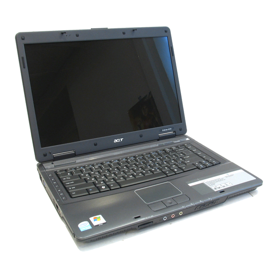
Page 15: Your Acer Notebook Tour
Your Acer Notebook tour After knowing your computer features, let us show you around your new TravelMate computer. TravelMate 4200 front view Icon Chapter 1 Item Display screen Also called LCD (liquid-crystal display), displays computer output. Keyboard For entering data into your computer. -
Page 16: Closed Front View
Closed Front View Item Item Icon Speaker Bluetooth communication button/ indicator Wireless communication button/ indicator Power indicator Icon Item Battery indicator Icon Item Microphone-in jack Line-in jack Headphones/ speakers/line-out jack with S/PDIF support Latch Description Description Item Description "Easy-launch buttons" on page 18 Left and right speakers deliver stereo audio output. -
Page 17: Left View
Left View Icon Right View Icon Chapter 1 Item Kensington lock slot Connects to a Kensington-compatible computer security lock. Ventilation slots Enables the computer to stay cool, even after prolonged use. Two USB 2.0 ports Connects to USB 2.0 devices (e.g., USB mouse, USB camera). -
Page 18: Rear Panel
Rear Panel Icon Base view Item Battery lock Cooling fan Hard disk bay Ethernet (RJ-45) Connects to an Ethernet 10/100/1000- based network. Item DC-in jack Connects to an AC adapter. External display Connects to a display device(e.g., (VGA) port external monitor, LCD projector). Battery Powers the computer Description... - Page 19 Indicators The computer has four easy-to-read status indicators on the upper-right above the keyboard, and four on the front panel. TravelMate 4200: The power, battery and wireless communication status indicators are visible even when the LCD display is closed. Icon...
- Page 20 Web browser, Empowering Key “ Press “ “ to run the Acer Empowering Technology. The mail and Web browser buttons are pre-set to email and Internet programs, but can be reset by users. To set the Web browser, mail and programmable buttons, run the Acer Launch Manager.
-
Page 21: Using The Keyboard
Lock Keys and embedded numeric keypad The keyboard has three lock keys which you can toggle on and off. Aspire Series: TravelMate 4200: Lock Key Caps Lock When Caps Lock is on, all alphabetic characters typed are in uppercase. -
Page 22: Windows Keys
BIOS utility. To activate hot keys, press and hold the <Fn> key before pressing the other key in the hotkey combination. Aspire Series: TravelMate 4200: Num Lock On Num Lock Off Type the letters in a normal manner. - Page 23 Fn-y Fn-x Chapter 1 Function Hot key help Displays help on hot keys. Acer eSetting Launches the Acer eSettings in Acer eManager. Acer Launches the Acer ePowerManagement in Acer ePowerManagement eManager. Sleep Puts the computer in Sleep mode. Display toggle Switches display output between the display screen, external monitor (if connected) and both.
-
Page 24: Special Key
You can locate the Euro symbol and US dollar sign at the upper-center and/or bottom-right of your keyboard. To type: Aspire Series: TravelMate 4200: The Euro symbol Open a text editor or word processor. Either directly press the <Euro> symbol at the bottom-right of the keyboard, or hold <Alt Gr> and then press the<5>... -
Page 25: Acer Empowering Technology
Help function. Acer eDataSecurity Management Acer eDataSecurity Management is handy file encryption utility that protexts your files from being accessed by unauthorized persons. It is conveniently integrated with Windows explorer as a shell extension for quick and Chapter 1 >... - Page 26 easy data encryption/decryption and also supports on-the-fly file encryption for MSN Messager and Microsoft Outlook. There are two passwords that can be used to encrypt/decrypt a file; the supervisor passowrd and the file- specific password. The supervisor passwork is a “master” password that cna decrypt any file on your system; the file-specific password will be used to encrypt files by default, or you cna choose to enter your own file- specific password when encrypting a file.
-
Page 27: Acer Elock Management
Floppy disk drives - 3.5-inch disks only. To activate Acer eLock Management, a password must be set first. Once set, you may apply lock to any of the three kinds of devices. Lock(s) will immediately be set without any reboot necessary, and will remain locked after rebooting, until unlocked. -
Page 28: Acer Eperformance Management
Acer ePerformance Management Acer ePerformance Management is a system optimization tool that boosts the performance of your Acer notebook. It provides you with the following options to enhance overall system performance: Memory optimization - releases unused memory and check usage. -
Page 29: Acer Erecovery Management
Acer eRecovery Management Acer eRecovery Management is a powerful utility that does away with the need for recovery disks provided by the manufacturer. The Acer eRecovery Management utility occupies space in a hidden partition on your system’s HDD. User-created backups are stored on D:\ drive. Acer eRecovery Management provides you with: Password protection. -
Page 30: Acer Esettings Management
NOTE: If your computer did not come with a Recovery CD or System CD, please use Acer eRecovery Management’s “System backup to optical disk” feature to burn a backup image to CD or DVD. To ensure the best results when recovering your system using a CD or Acer eRecovery Management, detach all peripherals (except the external Acer ODD, if your computer has one), including your Acer ezDock. -
Page 31: Acer Enet Management
To access this utility, either click on the “Acer eNet Management” icon on your notebook, or start the program from the Start menu. You also have the option to set Acer eNet Management to start automatically when you boot up your PC. -
Page 32: Acer Epower Management
Acer eNet Management does not store username and password information. Acer ePower Management Acer ePower Management features a straightforward user interface. To launch it, select Acer ePower Management from the Empowering Technology interface, or double-click the Acer ePower Management icon in the task tray. - Page 33 You can also click “Advanced Settings” to: Set alarms. Re-load factory defaults. Select what actions will be taken when the cover is closed, and set passwords for accessing the system after Hibernation or Standby. View information about Acer ePower Management. Chapter 1...
- Page 34 Acer ePresentation Management Acer ePresentation Management lets you select from two of the most common projector resolutions: XGA and SVGA. Chapter 1...
-
Page 35: Hardware Specifications And Configurations
Hardware Specifications and Configurations Processor Item CPU type Core logic CPU package CPU core voltage BIOS Item BIOS vendor BIOS Version BIOS ROM type BIOS ROM size BIOS package Supported protocols BIOS password control Second Level Cache Item Cache controller Cache size 1st level cache control 2st level cache control... - Page 36 Memory Combinations Slot 1 128MB 128MB 128MB 128MB 256MB 256MB 256MB 256MB 512MB 512MB 512MB 512MB 1024MB 1024MB 1024MB 1024MB 1024MB NOTE: Above table lists some system memory configurations. You may combine DIMMs with various capacities to form other combinations. On above table, the configuration of slot 1 and slot 2 could be reversed.
- Page 37 Bluetooth Interface Item Data throughput Protocol Interface Connector type Wireless Module 802.11b/g (optional device) Item Chipset Data throughput Protocol Interface Hard Disk Drive Interface Item Vendor & Seagate 40G ST9402112A Model Name Toshiba MK4025GAS Hitachi HTS421240H9AT00 WD WD400UE-22HCT0 Samsung M40MP0402H Capacity (MB) 40000 Bytes per...
- Page 38 Combo Drive Interface Item Vendor & model name Performance Specification Transfer rate (KB/sec) Buffer Memory Interface Applicable disc format Loading mechanism Power Requirement Input Voltage DVD-Dual Interface Item Vendor & model name Performance Specification Transfer rate (KB/sec) Buffer Memory Interface Applicable disc format Loading mechanism Power Requirement...
- Page 39 HD Audio Interface Item Audio onboard or optional Mono or Stereo Resolution Compatibility Mixed sound source Voice channel Sampling rate Internal microphone Internal speaker / Quantity Video Interface Item Chipset Package Interface Supports ZV (Zoomed Video) port Memory Interface Memory Bandwidth(GB/sec) Fill Rate (Gpixels/sec) Vertices/Second (Millions) Memory Data Rate (MHz)
- Page 40 USB Port Item Number of USB port Location Serial port function control PCMCIA Port Item PCMCIA controller Supports card type Number of slots Access location Supports ZV (Zoomed Video) port Supports 32 bit CardBus System Board Major Chips Item Core logic USB 2.0 Super I/O controller MODEM...
- Page 41 Battery Item Battery Type Pack capacity Number of battery cell Package configuration Normal voltage Charge voltage LCD 14.1” inch Item Vendor & model name Screen Diagonal (mm) Active Area (mm) Display resolution (pixels) Pixel Pitch Pixel Arrangement Display Mode Typical White Luminance (cd/m also called Brightness Luminance Uniformity Contrast Ratio...
- Page 42 LCD Inverter Item Vendor & model name Brightness conditions Input voltage (V) Input current (mA) Output voltage (V, rms) Output current (mA, rms) Output voltage frequency (k Hz) AC Adaptor Item Input rating Maximum input AC current Inrush current Efficiency System Power Management ACPI mode Mech.
-
Page 43: System Utilities
ATAPI Model Name : None ATAPI Serial Number : BIOS Version: V1.10 Intel V1256 VGA BIOS Ver xxxxxxxxxxxxxxxxxxxxxx Serial Number Asset Tag Number Produce Name TravelMate 4200 Manufacturer Name: Acer xxxxxxxxxxxxxxxxxxxxxxxxxxxxxxxx UUID: Help Select Item ↑ ↓ ← → Exit Select Menu Chapter 2 during POST (when “Press <F2>... -
Page 44: Navigating The Bios Utility
Navigating the BIOS Utility There are six menu options: Info., Main, System Devices, Security, Boot, and Exit. Follow these instructions: To choose a menu, use the cursor left/right keys (zx). To choose a parameter, use the cursor up/down keys ( wy). To change the value of a parameter, press por q. - Page 45 ATAPI Model Name : None ATAPI Serial Number : BIOS Version: V1.10 Intel V1256 VGA BIOS Ver xxxxxxxxxxxxxxxxxxxxxx Serial Number Asset Tag Number Produce Name TravelMate 4200 Manufacturer Name: Acer xxxxxxxxxxxxxxxxxxxxxxxxxxxxxxxx UUID: Help ↑ ↓ Select Item ← → Exit Select Menu NOTE: The system information is subject to different models.
- Page 46 Main The Main screen displays a summary of your computer hardware information, and also includes basic setup parameters. It allows the user to specify standard IBM PC AT system parameters. Information Main System Time: [22:03:28] System Date: [12/21/2005] System Memory: 640 KB Extended Memory: 255 MB...
- Page 47 The table below describes the parameters in this screen. Settings in boldface are the default and suggested parameter settings. Parameter System Time Sets the system time. The hours are displayed with 24-hour format. System Date Sets the system date. System Memory This field reports the memory size of the system.
- Page 48 Advanced The Advanced screen contains parameters involving your hardware devices. It also provides advanced settings of the system. Information Main Infrared Port (FIR) Help Select Item ↑ ↓ ← → Exit Select Menu The table below describes the parameters in the screen. Settings in boldface are the default and suggested parameter settings.
-
Page 49: Security
Security The Security screen contains parameters that help safeguard and protect your computer from unauthorized use. Information Main Supervisor Password Is : User Password Is : HDD Password Is: Set Supervisor Password Set User Password Set Hdd Password Password on Boot Help ↑... -
Page 50: Setting A Password
The table below describes the parameters in this screen. Settings in boldface are the default and suggested parameter settings. Parameter User Password is Supervisor Password is Set User Password Set Supervisor Password Primary HardDisk Security Password on Boot NOTE: When you are prompted to enter a password, you have three tries before the system halts. Don’t forget your password. -
Page 51: Changing A Password
Use the w and y keys to highlight the Set Supervisor Password parameter and press the e key. The Set Password box appears: Type the current password in the Enter Current Password field and press e. Press e twice without typing anything in the Enter New Password and Confirm New Password fields. The computer then sets the Supervisor Password parameter to “Clear”. - Page 52 If the new password and confirm new password strings do not match, the screen will display the following message. Chapter 2...
- Page 53 Boot This menu allows the user to decide the order of boot devices to load the operating system. Bootable devices includes the distette drive in module bay, the onboard hard disk drive and the CD-ROM in module bay. Information Main Boot priority order: 1: IDE 0: TOSHIBA MK6025GAS-(PM)
- Page 54 Exit The Exit screen contains parameters that help safeguard and protect your computer from unauthorized use. Information Main Exit Saving Changes Exit Disarding Changes Load Setup Defaults Discard Changes Save Changes Help Select Item ↑ ↓ ← → Exit Select Menu The table below describes the parameters in this screen.
-
Page 55: Bios Flash Utility
BIOS Flash Utility The BIOS flash memory update is required for the following conditions: New versions of system programs New features or options Restore a BIOS when it becomes corrupted. Use the Phlash utility to update the system BIOS flash ROM. NOTE: If you do not have a crisis recovery diskette at hand, then you should create a Crisis Recovery Diskette before you use the Phlash utility. - Page 56 Chapter 2...
-
Page 57: Machine Disassembly And Replacement
Machine Disassembly and Replacement This chapter contains step-by-step procedures on how to disassemble the notebook computer for maintenance and troubleshooting. To disassemble the computer, you need the following tools: Wrist grounding strap and conductive mat for preventing electrostatic discharge Small Philips screw driver Philips screwdriver Plastic flat head screw driver Tweezers... -
Page 58: General Information
General Information Before You Begin Before proceeding with the disassembly procedure, make sure that you do the following: Turn off the power to the system and all peripherals. Unplug the AC adapter and all power and signal cables from the system. Remove the battery pack. -
Page 59: Disassembly Procedure Flowchart
Disassembly Procedure Flowchart The flowchart on the succeeding page gives you a graphic representation on the entire disassembly sequence and instructs you on the components that need to be removed during servicing. For example, if you want to remove the system board, you must first remove the keyboard, then disassemble the inside assembly frame in that order. - Page 60 LCD Panel G*2 for 15.4" Wireless Antenna Set Screw List Item Description SCREW M2.5*3(NL) SCREW M2.5*6(NL) SCREW M2.5*10(NL) SCREW M2.5*15(NL) SCREW M2*2.2 SCREW M2*3(NL) SCREW M2*4 SCREW M3*4(NL) SCREW D-SUB 4#X40* 1/5-NI (NL) LCD Module LCD Bezel G*1 for 15" G*2 for 15.4"...
-
Page 61: Removing The Battery Pack
Removing the Battery Pack Slide the battery latch then remove the battery. Chapter 3... -
Page 62: Removing The Hdd Module
Removing the HDD Module/Memory/System Fan/Thermal Module/ CPU/ODD Module and LCD Module Removing the HDD Module Remove the two screws fastening the HDD door. Detach the HDD door from the notebook. Pull the HDD module outwards to disconnect the HDD module from the main board. Take out the HDD module carefully. - Page 63 Remove the two screws fastening the system fan. Take out the system fan from the main unit. Remove the four screws fastening the thermal module. Then detach the thermal module carefully. 10. Use a flat-headed screwdriver to release the CPU lock (Turn anti-clockwise). 11.
-
Page 64: Removing The Odd Module
14. Remove the screw holding the mini cover. 15. Detach the mini cover from the main unit. Removing the ODD Module First, remove the screw fastening the ODD module as shown. Push the ODD module outwards then remove it. Removing the LCD Module Open the LCD module as shown (See the left and the middle picture). - Page 65 Disconnect the keyboard cable from the main board. Turn over the notebook, remove two screws fastening the LCD module on the bottom. Then turn the notebook to the front side. Take out the antenna then disconnect the LCD cable (See the middle and the right images).
-
Page 66: Disassembling The Main Unit
Disassembling the Main Unit Separate the Main Unit Into the Upper and the Lower Case Assembly Remove two screws fastening the upper case assembly to the lower case assembly. Disconnect the LED board cable from the main board. Disconnect the touchpad cable from the main board. Remove eight screws fastening the upper case assembly and the lower case assembly on the bottom as shown. -
Page 67: Disassembling The Lower Case Assembly
12. Disconnect the touchpad FFC. 13. Then remove the touchpad FFC from the touchpad. 14. Detach the touchpad from the upper case. Disassembling the Lower Case Assembly Detach the switch board from the main board. Remove the screw fastening the modem board. Disconnect the modem board from the main board then detach the modem board. - Page 68 Remove the screw fastening the main board to the lower case. Pull the lower case outwards as the image shows and detach the main board from the lower case carefully. Take out the microphone from the lower case. 10. Remove the two screws fastening the speaker set. 11.
-
Page 69: Disassembling The Lcd Module
Disassembling the LCD Module Remove the four screw caps as shown. Remove the four screws holding the LCD bezel. Then detach the LCD bezel from the LCD module. Remove the screw fastening the LCD inverter. Take out the LCD inverter from the LCD cover, then disconnect the LCD cable from the inverter. Disconnect the LCD power cable on the other side. - Page 70 12. Remove the four screws holding the LCD left bracket. 13. Remove the LCD left bracket. Chapter 3...
-
Page 71: Disassembling The External Modules
Disassembling the External Modules Disassembling the HDD Module Remove two screws hodling the HDD bracket on one side. Remove another two screws fastening the HDD bracket on the other side. Detach the HDD from the HDD bracket. Disassembling the ODD Module Remove the three screws holding the optical bracket. - Page 72 Chapter 3...
-
Page 73: Table Of Contents
Troubleshooting Use the following procedure as a guide for computer problems. NOTE: The diagnostic tests are intended to test only Acer products. Non-Acer products, prototype cards, or modified options can give false errors and invalid system responses. Obtain the failing symptoms in as much detail as possible. -
Page 74: System Check Procedures
System Check Procedures External Diskette Drive Check Do the following to isolate the problem to a controller, driver, or diskette. A write-enabled, diagnostic diskette is required. NOTE: Make sure that the diskette does not have more than one label attached to it. Multiple labels can cause damage to the drive or cause the drive to fail. -
Page 75: Memory Check
If any of these devices do not work, reconnect the cable connector and repeat the failing operation. Memory check Memory errors might stop system operations, show error messages on the screen, or hang the system. Boot from the diagnostics diskette and start the doagmpstotics program (please refer to main board. Go to the diagnostic memory in the test items. -
Page 76: Check The Power Adapter
Check the Power Adapter Unplug the power adapter cable from the computer and measure the output voltage at the plug of the power adapter cable. See the following figure If the voltage is not correct, replace the power adapter. If the voltage is within the range, do the following: Replace the System board. -
Page 77: Check The Battery Pack
Check the Battery Pack To check the battery pack, do the following: From Software: Check out the Power Management in control Panel In Power Meter, confirm that if the parameters shown in the screen for Current Power Source and Total Battery Power Remaining are correct. -
Page 78: Power-On Self-Test (Post) Error Message
Power-On Self-Test (POST) Error Message The POST error message index lists the error message and their possible causes. The most likely cause is listed first. NOTE: Perform the FRU replacement or actions in the sequence shown in FRU/Action column, if the FRU replacement does not solve the problem, put the original part back in the computer. -
Page 79: Error Message List
Index of Error Messages Error Code List Error Codes <No error code> <No error code> Error Message List Error Messages Failure Fixed Disk Stuck Key Keyboard error Keyboard Controller Failed Keyboard locked - Unlock key switch Monitor type does not match CMOS - Run Setup Run “Load Default Settings” in BIOS Setup Utility. Shadow RAM Failed at offset: nnnn System RAM Failed at offset: nnnn Extended RAM Failed at offset: nnnn... - Page 80 Error Message List Error Messages Real time clock error Previous boot incomplete - Default configuration used Memory size found by POST differed from CMOS Diskette drive A error Incorrect Drive A type - run SETUP System cache error - Cache disabled CPU ID: DMA Test Failed Software NMI Failed...
- Page 81 Error Message List No beep Error Messages No beep, power-on indicator turns off and LCD is blank. No beep, power-on indicator turns on and LCD is blank. No beep, power-on indicator turns on and LCD is blank. But you can see POST on an external CRT.
-
Page 82: Phoenix Bios Beep Codes
Phoenix BIOS Beep Codes Code Beeps Verify Real Mode Disable Non-Maskable Interrupt (NMI) Get CPU type Initialize system hardware Initialize chipset with initial POST values Set IN POST flag Initialize CPU registers Enable CPU cache Initialize caches to initial POST values Initialize I/O component Initialize the local bus IDE Initialize Power Management... - Page 83 Code Chapter 4 Beeps 2-1-2-3 Check ROM copyright notice Check video configuration against CMOS Initialize PCI bus and devices Initialize all video adapters in system QuietBoot start (optional) Shadow video BIOS ROM Display BIOS copyright notice Display CPU type and speed Initialize EISA board Test keyboard Set key click if enabled...
- Page 84 Code Beeps Initialize floppy controller Determine number of ATA drives (optional) Initialize hard-disk controllers Initialize local-bus hard-disk controllers Jump to UserPatch2 Build MPTABLE for multi-processor boards Install CD ROM for boot Clear huge ES segment register Fixup Multi Processor table Search for option ROMs.
- Page 85 Code Code Chapter 4 Beeps Unknown interrupt Beeps Initialize the chipset Initialize the bridge Initialize the CPU Initialize the system timer Initialize system I/O Check force recovery boot Checksum BIOS ROM Go to BIOS Set Huge Segment Initialize Multi Processor Initialize OEM special code Initialize PIC and DMA Initialize Memory type...
-
Page 86: Index Of Symptom-To-Fru Error Message
Index of Symptom-to-FRU Error Message LCD-Related Symptoms Symptom / Error LCD backlight doesn't work LCD is too dark LCD brightness cannot be adjusted LCD contrast cannot be adjusted Unreadable LCD screen Missing pels in characters Abnormal screen Wrong color displayed LCD has extra horizontal or vertical lines displayed. - Page 87 Power-Related Symptoms Symptom / Error Battery can’t be charged PCMCIA-Related Symptoms Symptom / Error System cannot detect the PC Card (PCMCIA) PCMCIA slot pin is damaged. Memory-Related Symptoms Symptom / Error Memory count (size) appears different from actual size. Speaker-Related Symptoms Symptom / Error In Windows, multimedia programs, no sound comes from the computer.
- Page 88 Power Management-Related Symptoms Symptom / Error Battery fuel gauge in Windows doesn’t go higher than 90%. System hangs intermittently. Peripheral-Related Symptoms Symptom / Error System configuration does not match the installed devices. External display does not work correctly. USB does not work correctly Print problems.
-
Page 89: Intermittent Problems
Intermittent Problems Intermittent system hang problems can be caused by a variety of reasons that have nothing to do with a hardware defect, such as: cosmic radiation, electrostatic discharge, or software errors. FRU replacement should be considered only when a recurring problem exists. When analyzing an intermittent problem, do the following: Run the advanced diagnostic test for the system board in loop mode at least 10 times. -
Page 90: Undetermined Problems
System Check” on page 71.): Power-off the computer. Visually check them for damage. If any problems are found, replace the FRU. Remove or disconnect all of the following devices: Non-Acer devices Printer, mouse, and other external devices Battery pack Hard disk drive... -
Page 91: Jumper And Connector Locations
Jumper and Connector Locations Board Layout Top View LCD Connector Lid Switch MDC Connector Power Button Connector Media Board Connector Touchpad Board Connector JP43 SIM Card Connector Touchpad Right Button Touchpad Left Button Chapter 5 Touchpad Down Button Touchpad Up Button Touchpad Left Button Touchapd Left Button JP13... - Page 92 Bottom View NOTE: This is engineering sample. The image above may not be exactly the same as the real main board you get. JP19 FAN Connector VGA Chipset JP18 CPU Socket JP16 DVI Connector JP15 CRT Connector JP14 TV-Out Connector PCN1 DC-IN Jack JP17...
- Page 93 Jumper Board Layout Switch Board Top View Label Media Board Top View Label Chapter 5 Description Arcade/TV tunver switch Volume Up switch Volume Down switch Play/Pause switch Stop switch Forward/Next switch Backward/Previous switch Description Power Button E-mail Button Internet Button User Button E-Power Button...
- Page 94 Media Board Bottom View Label LS-2923P Power Board Top View Label Description USB Connector USB Connector RF INe Connector RF Cable Connector AV IN Connector Board to Main Board Connector Description SIM Card Connector Chapter 5...
- Page 95 Jumper Setting Label Chapter 5 Description Clear CMOS Jumper Note: J3 locates at bottom side of the main board as the red circle highlighted.
- Page 96 Chapter 5...
-
Page 97: Field Replaceable Unit
DIFFERENT part number code from those given in the FRU list of this printed Service Guide. You MUST use the local FRU list provided by your regional Acer office to order FRU parts for repair and service of customer machines. -
Page 98: Exploded Diagram
Exploded Diagram The exploded diagram is not available as the service guide released. We will update this chapter as soon as we get the data from our vendor. Chapter 6... - Page 99 MINI PCI WIRELESS BOARD 802.11 A/B/G JPN SWITCH BOARD W/O TV AS/TM SIM BOARD W/FFC INVERTER BOARD - 15 IN. INVERTER BOARD - 15.4 IN. EXPRESS CARD FFC CABLE - T/P TO MB Acer PN AP.09001.003 AP.09003.006 AP.09006.004 BT.00603.017 BT.00605.004 BT.00604.008 54.TAVV5.001 54.TAVV5.002...
- Page 100 POWER CORD INDIA 3 PIN POWER CORD TWN 3 PIN MIDDLE COVER TM UPPER CASE TM W/O TV LOWER CASE W/O CARD 1394 FIR DVI TV THERMAL DOOR MINI DOOR T/P BRACKET W/MYLAR Acer PN 50.TAVV5.002 50.TAVV5.003 50.TAVV5.004 50.TAVV5.005 27.TAVV5.001 27.TAVV5.002 27.TAVV5.003 27.TAVV5.004 27.TAVV5.005...
- Page 101 LCD PANEL 15.4 IN. WITH LOGO W/ 15.4 IN. ANTENNA TM LCD BEZEL - 15 IN. LCD BEZEL - 15.4 TEXTURE LCD BRACKET SET (R&L) - 15 LCD BRACKET SET (R&L) - 15.4 Acer PN 33.TAVV5.002 42.TAVV5.004 33.TAVV5.003 42.TAVV5.005 42.TAVV5.006 42.TAVV5.010...
- Page 102 GSA-4028N TRAY IN HDD PATA 80G 5400RPM SEAGATE MERCURY2 ST98823A FW:3.04 (ROHS) HDD PATA 80G 5400RPM HGST MORAGA+ HTS541080G9AT00 FW:A56J (ROHS) HDD PATA 80G 5400RPM WD ML40 WD800-22HCTO (ROHS) Acer PN 50.TAVV5.011 50.TAVV5.012 47.TAVV5.001 47.TAVV5.006 47.TAVV5.002 KC.26001.DTP KC.25001.DTP KC.24001.DTP KC.23001.DTP KO02406.13...
- Page 103 ASSY LCD MODULE 15 IN. XGA AUO (B150XG02. V4) TM FOR WIRELESS ASSY LCD MODULE 15.4 WXGA TM FOR WIRELESS MAINBOARD 945GM UMA 10/100 W/ O EXPRESS CARD, CARD READER, CPU, MEMORY PCMCIA SOCKET Acer PN KB.TNT07.001 KB.TNT07.003 KB.TNT07.023 KB.TNT07.018 KB.TNT07.002 KB.TNT07.014 KB.TNT07.021 KB.TNT07.012...
- Page 104 THERMAL MODULE - CPU NAME PLATE - TM4200 RUBBER FOOT - LARGE RUBBER FOOT - MIDDLE RUBBER FOOT - SMALL LATCH RUBBER THERMAL DOOR RUBBER TOUCHPAD W/SPONGE SPEAKER SET (R&L) Acer PN KN.51203.023 KN.51202.021 KN.51204.019 KN.5120B.015 KN.5120G.005 23.TAVV5.001 60.TAVV5.009 40.TAVV5.001 47.TAVV5.003...
- Page 105 SCREW D-SUB 4#X40* 1/5-NI (NL) Chapter 6 DESCRIPTION SCREW M2.5*3(NL) SCREW M2.5*6(NL) SCREW M2.5*10(NL) SCREW M2.5*15(NL) SCREW M2*2.2 SCREW M2*3(NL) SCREW M2*4 SCREW M3*4(NL) SCREW D-SUB 4#X40* 1/5-NI (NL) Acer PN 86.TAVV5.001 86.TAVV5.002 86.TAVV5.003 86.TAVV5.004 86.TAVV5.005 86.TAVV5.006 86.TAVV5.007 86.TAVV5.008 86.TAVV5.009...
- Page 106 Chapter 6...