Acer TravelMate 3200 Service Manual
Hide thumbs
Also See for TravelMate 3200:
- Manuel d'utilisation (92 pages) ,
- Guía del usuario (92 pages) ,
- Manual do utilizador (92 pages)

Related Manuals for Acer TravelMate 3200


Summary of Contents for Acer TravelMate 3200
- Page 1 Acer TravelMate 3200 Series Service Guide Service guide files and updates are available on the ACER/CSD web; for more information, please refer to http://csd.acer.com.tw PRINTED IN TAIWAN...
-
Page 2: Revision History
Revision History Please refer to the table below for the updates made on TravelMate 3200 service guide. Date Chapter Updates... - Page 3 Copyright Copyright © 2004 by Acer Incorporated. All rights reserved. No part of this publication may be reproduced, transmitted, transcribed, stored in a retrieval system, or translated into any language or computer language, in any form or by any means, electronic, mechanical, magnetic, optical, chemical, manual or otherwise, without the prior written permission of Acer Incorporated.
- Page 4 Conventions The following conventions are used in this manual: SCREEN MESSAGES NOTE WARNING CAUTION IMPORTANT Denotes actual messages that appear on screen. Gives bits and pieces of additional information related to the current topic. Alerts you to any damage that might result from doing or not doing specific actions.
- Page 5 DIFFERENT part number code to those given in the FRU list of this printed Service Guide. You MUST use the list provided by your regional Acer office to order FRU parts for repair and service of customer machines.
-
Page 7: Table Of Contents
Table of Contents Chapter 1 System Specifications Features ............1 System Block Diagram . - Page 8 TravelMate 3200 Series ........
-
Page 9: System Specifications
The 14.1” XGA (1024x768 resolution) SXGA+ (will ship)TFT LCD panel providing a large viewing area for maximum efficiency and ease-of-use 3D graphics support TravelMate 3200 series employs ATI MOBILITY (manufacturing option) Simultaneous display on LCD and CRT monitor, and other display devices like projector support “Automatic LCD dim”... - Page 10 Expansion One Type II CardBus PC Card slot Upgradeable memory modules Acer EasyPort I/O Ports One Type II PC Card slot One RJ-11 phone jack (V.90/92) One RJ-45 jack for LAN (Ethernet 10/100/1000 Base-T) One 100-pin port replicator One external monitor port One line-out jack (3.5mm minijack)
-
Page 11: System Block Diagram
Page : 19 USB * 2 Page :22 BATT CHARGER PAGE :30 USB ICSI 1213 3 IN 1 DC/DC PAGE :25,26,27,28 DAUGHTER BOARD Acer Inc. Size Document Number Custom BLOCK DIAGRAM Date: Thursday, April 22, 2004 USB 2.0 Conn. Sheet... -
Page 12: Board Layout
Board Layout Top View Chapter 1... - Page 13 RJ11 1394 Connector USB Connector VGA Connector Modem Cable Connector LCD Connector Internal MIC Connector Battery Connector FAN Connector Line-out Connector MIC Connector Speaker Connector DDR SO-DIMM (TOP) Chapter 1 Bluetooth Connector MDC Connector BIOS Socket ODD Connector Touchpad Connector Keyboard Connector QSB Cable Connector RTC battery Connector...
-
Page 14: Bottom View
Bottom View Chapter 1... - Page 15 DDR SO-DIMM (BOT) HDD Connector Mini-PCI Slot Chapter 1 PCMCIA Connector PCMCIA Slot...
-
Page 16: Outlook View
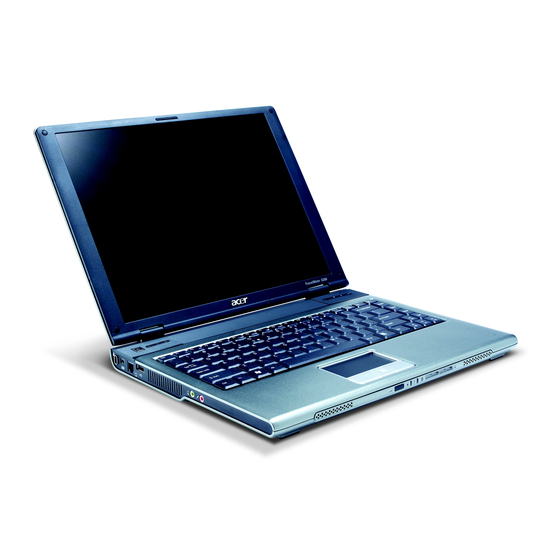
Outlook View A general introduction of ports allow you to connect peripheral devices, as you would with a desktop PC. Front Open View Icon Item Display screen Also called LCD (liquid-crystal display), displays computer output. Power button Turns on the computer. Status indicators Light-Emitting Diodes (LEDs) that turn on and off to show the status of the... - Page 17 Microphone Internal microphone for sound recording. Chapter 1...
-
Page 18: Front Closed View
Front Closed View Item Icon Speakers Infrared port Power indicator Battery indicator Bluetooth communications Wireless communication NOTE: The Bluetooth and Wireless buttons and indicators only work on models with Bluetooth and Wireless features, respectively. Note Description Item Description Left and right speakers deliver stereo audio output. -
Page 19: Left View
Left View Item Icon Security keylock IEEE 1394 port Modem jack USB port Ventilation slots Speaker/Line-Out/ Headphone jack Microphone jack Chapter 1 Description Item Description Connects to a Kensington-compatible computer security lock. Connects to IEEE 1394 devices. Connects to aphone line. Connect to Universal Serial Bus (USB) 2.0 devices (e.g., USB mouse, USB camera). -
Page 20: Right Panel
Right Panel Item Icon Description Item Optical drive Internal optical drive; accepts CDs or DVDs depending on the optical drive type. LED indicator Lights up when the optical drive is active. Emergency eject hole Ejects the optical drive tray when the computer is turned off. -
Page 21: Rear Panel
Rear Panel Item Icon Chapter 1 Description Item Expansion port Connects to I/O port replicator or EasyPort expansion devices. External display port Connects to a display device (e.g., external monitor, LCD projector). Description... -
Page 22: Bottom Panel
Bottom Panel Bottom view Item Icon Memory compartment Cooling fan Battery release latches Unlatches the battery to remove the battery Battery bay Battery lock Description Item Description Houses the computer’s main memory. Helps keep the computer cool. Note: Don’t cover or obstruct the opening Note of the fan. -
Page 23: Indicators
Indicators The computer has three easy-to-read status icons on the upper-left above the keyboard. Icon Function Icon Function Caps lock Num lock Media Activity In addition, there are two indicators at the front panel. Even when the cover is closed, the state or features can still b seen. - Page 24 Icon Function Power Battery Description Lights green when the power is on and orange when the computer is in standby mode. Lights orange when the battery is charging. Chapter 1...
-
Page 25: Using The Keyboard
Using the Keyboard The keyboard has full-sized keys and an embedded keypad, separate cursor keys, two Windows keys and twelve function keys. Lock Keys The keyboard has three lock keys which you can toggle on and off. Lock Key Lock Key Caps Lock When Caps Lock is on, all alphabetic characters typed are in uppercase. -
Page 26: Embedded Numeric Keypad
Embedded Numeric Keypad The embedded numeric keypad functions like a desktop numeric keypad. It is indicated by small characters located on the upper right corner of the keycaps. To simplify the keyboard legend, cursor-control key symbols are not printed on the keys. Desired Access Desired Access Number keys on embedded... -
Page 27: Windows Keys
Windows Keys The keyboard has two keys that perform Windows-specific functions. Icon Windows key Application Chapter 1 Description Description Pressed alone, this key has the same effect as clicking on the Windows Start button; it launches the Start menu. It can also be used with other keys to provide a variety of function: + Tab + Tab (Activates next taskbar button) -
Page 28: Hot Keys
Description Function Hot key help Displays help on hot keys. Acer eSetting Launches the Acer eSetting in the Acer eManager set by the Acer Empowering key. Acer Launches the Acer ePowerManagement in the Acer ePowerManagement eManager set by the Acer Empowering key. - Page 29 Hot Key Icon Fn-y Fn-x Fn-z Alt Gr-Euro Chapter 1 Function Volume down Decreases the speaker volume. Brightness up Increases the screen brightness. Brightness down Decreases the screen brightness Euro Types the Euro symbol. Description...
-
Page 30: The Euro Symbol
The Euro Symbol If your keyboard layout is set to United States-International or United Kingdom or if you have a keyboard with a European layout, you can type the Euro symbol on your keyboard. NOTE: For US keyboard users: The keyboard layout is set when you first set up Windows. For the Euro symbol to work, the keyboard layout has to be set to United States-International. -
Page 31: Launch Keys
Web browser, Empowering and programmable keys. Press the Acer Empowering Key to run the Acer EManager. The mail and Web browser are default for Email and Internet programs, but can be reset by users. To set the mail, Web browser and programmable keys, run the acer Launch Manager. - Page 32 Description Bluetooth Lights to indicate the status of Bluetooth communications (optional) communications. Wireless Lights to indicate the status of wireless LAN communication (optional) communications. Default application Chapter 1...
-
Page 33: Touchpad
Touchpad The built-in touchpad is a pointing device that senses movement on its surface. This means the cursor responds as you move your finger on the surface of the touchpad. The central location on the palmrest provides optimal comfort and support. NOTE: If you are using an external USB mouse, you can press Fn-F7 to disable the touchpad. - Page 34 Function Left Button Scroll NOTE: Keep your fingers dry and clean when using the touchpad. Also keep the touchpad dry and clean. The touchpad is sensitive to finger movements. Hence, the lighter the touch, the better the response. Tapping too hard will not increase the touchpad’s responsiveness. Right Button Scroll Button Click and hold...
-
Page 35: Hardware Specifications And Configurations
Hardware Specifications and Configurations Processor Item CPU type Core logic CPU package CPU core voltage BIOS Item BIOS vendor BIOS Version BIOS ROM type BIOS ROM size BIOS package Supported protocols BIOS password control Second Level Cache Item Cache controller Cache size 1st level cache control 2st level cache control... - Page 36 Memory Combinations Slot 1 128MB 128MB 128MB 128MB 256MB 256MB 256MB 256MB 512MB 512MB 512MB 512MB 1024MB 1024MB 1024MB 1024MB 1024MB NOTE: Above table lists some system memory configurations. You may combine DIMMs with various capacities to form other combinations. On above table, the configuration of slot 1 and slot 2 could be reversed.
- Page 37 Modem Interface Item Supports modem protocol Modem connector type Modem connector location Bluetooth Interface Item Chipset Data throughput Protocol Interface Wireless Module 802.11b (optional device) Item Chipset Data throughput Protocol Interface Wireless Module 802.11b/g (optional device) Item Chipset Data throughput Protocol Interface 3-in-1 card reader...
- Page 38 Hard Disk Drive Interface Item Performance Specifications Buffer size 2048KB/ Interface ATA/ATAPI-6; ATA-6 Max. media transfer rate (disk-buffer, Mbytes/s) Data transfer 100 MB/Sec. rate Ultra DMA mode-5 (host~buffer, Mbytes/s) DC Power Requirements Voltage 5V(DC) +/- 5% tolerance Combo Drive Interface Item Vendor &...
- Page 39 Audio Interface Item Resolution Compatibility Mixed sound source Voice channel Sampling rate Internal microphone Internal speaker / Quantity Audio Jack Item Number of audio jack Rated input Connector type Video Interface Item Chipset Package Interface Supports ZV (Zoomed Video) port Video Memory Item Chipset...
- Page 40 IEEE 1394 Port Item Location Connector type PCMCIA Port Item PCMCIA controller Supports card type Number of slots Access location Supports ZV (Zoomed Video) port Supports 32 bit CardBus System Board Major Chips Item Core logic IEEE 1394 USB 2.0 Super I/O controller MODEM Bluetooth...
- Page 41 Battery Item Number of battery cell Package configuration Normal voltage Charge voltage Item Vendor & model name Screen Diagonal (mm) Active Area (mm) Display resolution (pixels) Pixel Pitch Pixel Arrangement Display Mode Typical White Luminance (cd/m also called Brightness Luminance Uniformity Contrast Ratio Response Time (Optical Rise Time/Fall Time)msec...
- Page 42 AC Adaptor Item Input rating Maximum input AC current Inrush current Efficiency System Power Management ACPI mode Mech. Off (G3) Soft Off (G2/S5) Working (G0/S0) Suspend to RAM (S3) Save to Disk (S4) Specification 90VAC to 264VAC, 47Hz to 63Hz 3.16A 50A@115VAC 100A@230VAC...
-
Page 43: System Utilities
UJDA755 DVD/CDRW System BIOS Ver: 3A06 ATI M11-008.017M.146.000 VGA BIOS Ver: PQ1A27 KBC Ver: xxxxxxxxxxxxxxxxxxxxxx Serial Number Asset Tag Number: Product TravelMate 3200 Manufacturer Name: Acer xxxxxxxxxxxxxxxxxxxxxxxxxxxxxxxx UUID: Help Select Item ↑ ↓ ← → Exit Select Menu Chapter 2 during POST (when “Press <F2>... -
Page 44: Navigating The Bios Utility
Navigating the BIOS Utility There are six menu options: Info., Main, System Devices, Security, Boot, and Exit. Follow these instructions: To choose a menu, use the cursor left/right keys (zx). To choose a parameter, use the cursor up/down keys ( wy). To change the value of a parameter, press por q. -
Page 45: Information
ATAPI Device: UJDA755 DVD/CDRW System BIOS Ver: 3A06 ATI M11-008.017M.146.000 VGA BIOS Ver: PQ1A27 KBC Ver: xxxxxxxxxxxxxxxxxxxxxx Serial Number Asset Tag Number: Product TravelMate 3200 Manufacturer Name: Acer xxxxxxxxxxxxxxxxxxxxxxxxxxxxxxxx UUID: Help Select Item ↑ ↓ ← → Exit Select Menu Parameter IDE1 Model Name This field displays the model name of HDD installed on Primary IDE master. -
Page 46: Main
Main The Main screen displays a summary of your computer hardware information, and also includes basic setup parameters. It allows the user to specify standard IBM PC AT system parameters. Info. Main System Time: System Date: System Memory: Extended Memory: Video Memory Quiet Boot: Power on Display:... - Page 47 The table below describes the parameters in this screen. Settings in boldface are the default and suggested parameter settings. Parameter System Time Sets the system time. System Date Sets the system date. System Memory This field reports the memory size of the system. Memory size is fixed to 640KB Extended Memory This field reports the memory size of the...
-
Page 48: Advanced
Advanced The Advanced menu screen contains parameters involving your hardware devices. It also provides advanced settings of the system. Info. Main Serial Port Parallel port: Mode: Internal Touchpad: Infrared Port (FIR): Help Select Item ↑ ↓ ← → Exit Select Menu The table below describes the parameters in the screen. -
Page 49: Security
Security The Security screen contains parameters that help safeguard and protect your computer from unauthorized use. Info. Main Supervisor Password Is: User Password Is: Primary HardDisk Security: HDD Master ID: Set Supervisor Password Set User Passord Set HDD Password Password on Boot Help Select Item ↑... -
Page 50: Setting A Password
The table below describes the parameters in this screen. Settings in boldface are the default and suggested parameter settings. Parameter Supervisor Password is User Password is Set Supervisor Password Set User Password Primary Harddisk Security Password on Boot NOTE: When you are prompted to enter a password, you have three tries before the system halts. Don’t forget your password. - Page 51 After setting the password, the computer sets the User Password parameter to “Set”. If desired, you can opt to enable the Password on boot parameter. When you are done, press u to save the changes and exit the BIOS Setup Utility. Removing a Password Follow these steps: Use the w and y keys to highlight the Set Supervisor Password parameter and press the e key.
- Page 52 If the verification is OK, the screen will display as following. The password setting is complete after the user presses u. If the current password entered does not match the actual current password, the screen will show you the Setup Warning. If the new password and confirm new password strings do not match, the screen will display the following message.
-
Page 53: Boot
Boot This menu allows the user to decide the order of boot devices to load the operating system. Bootable devices includes the distette drive in module bay, the onboard hard disk drive and the CD-ROM in module bay. Info. Main Floppy Devices CD-ROM/DVD Drive +Hard Drive... -
Page 54: Exit
Exit The Exit screen contains parameters that help safeguard and protect your computer from unauthorized use. Info. Main Exit Saving Changes Exit Dicarding Changes Load Setup Defaults Discard Changes Save Changes Help Select Item ↑ ↓ ← → Exit Select Menu The table below describes the parameters in this screen. -
Page 55: Bios Flash Utility
BIOS Flash Utility The BIOS flash memory update is required for the following conditions: New versions of system programs New features or options Restore a BIOS when it becomes corrupted. Use the Phlash utility to update the system BIOS flash ROM. NOTE: If you do not have a crisis recovery diskette at hand, then you should create a Crisis Recovery Diskette before you use the Phlash utility. - Page 56 Chapter 2...
-
Page 57: Machine Disassembly And Replacement
Machine Disassembly and Replacement This chapter contains step-by-step procedures on how to disassemble the notebook computer for maintenance and troubleshooting. To disassemble the computer, you need the following tools: Wrist grounding strap and conductive mat for preventing electrostatic discharge Small Philips screw driver Philips screwdriver Plastic flat head screw driver Tweezers... -
Page 58: General Information
Unplug the AC adapter and all power and signal cables from the system. Remove the battery pack. NOTE: TravelMate 3200 series product uses mylar or tape to fasten the FFC/FPC/connectors/cable, you may need to tear the tape or mylar before you disconnect different FFC/FPC/connectors. -
Page 59: Disassembly Procedure Flowchart
Disassembly Procedure Flowchart The flowchart on the succeeding page gives you a graphic representation on the entire disassembly sequence and instructs you on the components that need to be removed during servicing. For example, if you want to remove the system board, you must first remove the keyboard, then disassemble the inside assembly frame in that order. - Page 60 SCREW M3.0*3.0-I NI SCREW MS25030IJ81 SCREW MM30035I354 SCREW MM25030IL65 SCREW MM25040I243 SCREW MM25050IL64 LCD Module LCD Bezel LCD Cover Assembly LCD coaxial cable Acer part No. 86.T23V7.009 86.A08V7.005 86.A03V7.013 86.T25V7.010 86.A03V7.019 86.T48V7.001 86.T48V7.002 86.T48V7.003 86.A10V7.007 86.A03V7.011 4 screw pads LCD Inverter...
-
Page 61: Removing The Battery Pack
Removing the Battery Pack Release the battery lock. Slide the battery latch. Remove the battery pack. Chapter 3... -
Page 62: And The Lcd Module
Removing the Wireless LAN Card/the HDD Module/the ODD Module/and the LCD module Removing the Wireless LAN Card Remove the two screws then remove the mini PCI cover. Disconnect the wireless antennae. Pop up the wireless LAN card then remove it. Removing the HDD Module Remove the five screws holding the DDR/HDD cover then remove the cover. -
Page 63: Removing The Lcd Module
Removing the LCD Module Remove the two screws holding the right hinge cover. Remove the two screws tightening the left hinge cover. Detach the right and the left hinge cover form the main unit. Disconnect the lid switch cable. Remove the two screws tightening the function board then remove it. Remove one screw holding the power board then remove it. - Page 64 11. Remove the three screws as shown. 12. Remove the two screws holding the right hinge. 13. Remove one screw tightening the left hinge. 14. Then remove the entire LCD module. Chapter 3...
-
Page 65: Disassembling The Main Unit
Disassembling the Main Unit Remove the Thermal Module Disconnect the fan cable. Remove the four screws tightening the thermal module. Remove the two screws as shown. Detach the thermal module from the main unit. Separate the Main Unit Into the Upper and the Lower Case Assembly Remove two screws as shown. -
Page 66: Disassembling The Upper Case Assembly
Disconnect the touchpad cable. Then detach the upper case assembly from the main unit. Disassembling the Upper Case Assembly Disconnect touchpad touchpad to touchpad board cable. Remove the seven screws tightening the touchpad bracket. Remove the touchpad bracket assembly. Then remove the touchpad assembly. Disconnect the touchpad to touchpad board cable. -
Page 67: Disassembling The Lower Case Assembly
Disassembling the Lower Case Assembly Disconnect the modem cable from the main board. Pop up the memory then remove it from the main board. Remove one screw that seucres the modem board. Disconnect the modem cable from the modem board then remove the modem board. Tear off the type fastening the modem cable on the main board. - Page 68 14. Tear off the type fastening the speaker set. 15. Remove the speaker set from the lower case. Chapter 3...
-
Page 69: Disassembling The Lcd Module
Disassembling the LCD Module Remove the four screw caps as shown. Then remove the four screws tightening the LCD bezel. Detach the LCD bezel from the LCD module. Then turn the LCD bezel over and remove the microphone. Tear off the type fastening the inverter cable then disconnect the inverter cable then remove the inverter. Remove the six screws holding the LCD to the LCD cover. - Page 70 12. Tear off the tape fastening the antennae set. 13. Then detach the antennae set from the LCD cover. Chapter 3...
-
Page 71: Disassembling The External Modules
Disassembling the External Modules Disassembling the HDD Module Remove the two screws holding the HDD bracket on one side. Remove the two screws holding the HDD bracket on the other side. Detach the hard disc drive from the HDD bracket. Disconnect the HDD cable then remove it. - Page 72 Chapter 3...
-
Page 73: Chapter 4 Troubleshooting
Troubleshooting Use the following procedure as a guide for computer problems. NOTE: The diagnostic tests are intended to test this model. Non-Acer products, prototype cards, or modified options can give false errors and invalid system responses. Duplicate symptom and obtain the failing symptoms in as much detail as possible. -
Page 74: System Check Procedures
System Check Procedures External Diskette Drive Check If an error occurs with the internal diskette drive, reconnect the diskette connector on the system board. If the error still remains: Reconnect the external diskette drive/DVD-ROM module. Replace the external diskette drive/CD-ROM module. Replace the main board. -
Page 75: Power System Check
Power System Check To verify the symptom of the problem, power on the computer using each of the following power sources: Remove the battery pack. Connect the power adapter and check that power is supplied. Disconnect the power adapter and install the charged battery pack; then check that power is supplied by the battery pack. -
Page 76: Touchpad Check
Check the Battery Pack To check the battery pack, do the following: From Software: Check out the Power Management in control Panel In Power Meter, confirm that if the parameters shown in the screen for Current Power Source and Total Battery Power Remaining are correct. -
Page 77: Power-On Self-Test (Post) Error Message
Power-On Self-Test (POST) Error Message The POST error message index lists the error message and their possible causes. The most likely cause is listed first. NOTE: Perform the FRU replacement or actions in the sequence shown in FRU/Action column, if the FRU replacement does not solve the problem, put the original part back in the computer. -
Page 78: Index Of Error Messages
Index of Error Messages Error Message List Error Messages Struck Key System CMOS checksum bad - Default configuration used Real time clock error Previous boot incomplete - Default configuration used Invalid System Configuration Data Operating system not found FRU/Action in Sequence See “Keyboard or Auxiliary Input Device Check”... - Page 79 Error Message List No beep Error Messages Power-on indicator turns off and LCD is blank. Power-on indicator turns on and LCD is blank. Power-on indicator turns on and LCD is blank. But you can see POST on an external CRT. Power-on indicator turns on and a blinking cursor shown on LCD during POST.
-
Page 80: Phoenix Bios Beep Codes
Phoenix BIOS Beep Codes Code Beeps Verify Real Mode Disable Non-Maskable Interrupt (NMI) Get CPU type Initialize system hardware Initialize chipset with initial POST values Set IN POST flag Initialize CPU registers Enable CPU cache Initialize caches to initial POST values Initialize I/O component Initialize the local bus IDE Initialize Power Management... - Page 81 Code Chapter 4 Beeps Check video configuration against CMOS Initialize PCI bus and devices Initialize all video adapters in system QuietBoot start (optional) Shadow video BIOS ROM Display BIOS copyright notice Display CPU type and speed Initialize EISA board Test keyboard Set key click if enabled 2-2-3-1 Test for unexpected interrupts...
- Page 82 Code Beeps Determine number of ATA drives (optional) Initialize hard-disk controllers Initialize local-bus hard-disk controllers Jump to UserPatch2 Build MPTABLE for multi-processor boards Install CD ROM for boot Clear huge ES segment register Fixup Multi Processor table Search for option ROMs. One long, two short beeps on checksum failure.
- Page 83 Code Chapter 4 Beeps Initialize the chipset Initialize the bridge Initialize the CPU Initialize the system timer Initialize system I/O Check force recovery boot Checksum BIOS ROM Go to BIOS Set Huge Segment Initialize Multi Processor Initialize OEM special code Initialize PIC and DMA Initialize Memory type Initialize Memory size...
-
Page 84: Index Of Symptom-To-Fru Error Message
Index of Symptom-to-FRU Error Message LCD-Related Symptoms Symptom / Error LCD backlight doesn't work LCD is too dark LCD brightness cannot be adjusted Unreadable LCD screen Missing pels in characters Abnormal screen Wrong color displayed LCD has extra horizontal or vertical lines displayed. - Page 85 Power-Related Symptoms Symptom / Error Battery can’t be charged or discharged System hang during POST PCMCIA-Related Symptoms Symptom / Error System cannot detect the PC Card (PCMCIA) PCMCIA slot pin is damaged. PC Card cannot be inserted or ejected Memory-Related Symptoms Symptom / Error Memory count (size) appears different from actual size.
- Page 86 Power Management-Related Symptoms Symptom / Error The system doesn't resume from hibernation/ standby mode. The system doesn't resume from standby mode after opening the lid of the portable computer. Battery fuel gauge in Windows doesn’t go higher than 90%. System hangs intermittently. Peripheral-Related Symptoms Symptom / Error System configuration does not match the...
- Page 87 Modem/LAN-Related Symptoms Symptom / Error Internal modem does not work correctly. Internal LAN does not work correctly NOTE: If you cannot find a symptom or an error in this list and the problem remains, see “Undetermined Problems” on page 81. Chapter 4 Action in Sequence Phone cable...
-
Page 88: Intermittent Problems
Intermittent Problems Intermittent system hang problems can be caused by a variety of reasons that have nothing to do with a hardware defect, such as: cosmic radiation, electrostatic discharge, or software errors. FRU replacement should be considered only when a recurring problem exists. When analyzing an intermittent problem, do the following: Run the diagnostic test for the system board in loop mode at least 10 times. -
Page 89: Undetermined Problems
System Check” on page 67): Power-off the computer. Visually check them for damage. If any problems are found, replace the FRU. Remove or disconnect all of the following devices: Non-Acer devices Printer, mouse, and other external devices Battery pack Hard disk drive... - Page 90 Chapter 4...
-
Page 91: Jumper And Connector Locations
Chapter 5 Jumper and Connector Locations Top View Chapter 5... - Page 92 RJ11 1394 Connector USB Connector VGA Connector Modem Cable Connector LCD Connector Internal MIC Connector Battery Connector FAN Connector Line-out Connector MIC Connector Speaker Connector DDR SO-DIMM (TOP) Bluetooth Connector MDC Connector CN12 BIOS Socket ODD Connector CN10 Touchpad Connector Keyboard Connector QSB Cable Connector CN11...
-
Page 93: Bottom View
Bottom View Chapter 5... - Page 94 DDR SO-DIMM (BOT) HDD Connector Mini-PCI Slot CN30 PCMCIA Connector CN31 PCMCIA Slot CN29 CN28 CN28 Chapter 5...
-
Page 95: Fru (Field Replaceable Unit) List
DIFFERENT part number code from those given in the FRU list of this printed Service Guide. You MUST use the local FRU list provided by your regional Acer office to order FRU parts for repair and service of customer machines. -
Page 96: Exploded Diagram
Exploded Diagram TravelMate 3200 FRU List Picture Adapter Battery Boards Cables Partname And Description ADAPTER 65W 3 PIN DELTA SADP-65KB BF ADAPTER 65W 3 PIN LITE-ON PA-1650-02 QA BATTERY SANYO LI-ION 3S2P 6CELL 4800mAH BATTERY SIMPLO LI-ION 3S2P 6CELL 4800mAH... - Page 97 TravelMate 3200 FRU List Picture Case/Cover/Bracket Assembly Chapter 6 Partname And Description FFC CABLE - TP/B TO MB LID SWICTH CABLE - HINGE COVER R MODEM CABLE SPARE PART BLUETOOTH CABLE HDD CONNECT CABLE POWER CORD US (3 pin) POWER CORD PRC ( 3 Pin)
- Page 98 TravelMate 3200 FRU List Picture Communication Module HDD/ Hard Disk Drive Keyboard Partname And Description LOWER CASE ASSY W/SPEAKER HDD SPONG HINGE COVER L HINGE COVER R TOUCHPAD BRACKET HDD BRACKET WIRELESS LAN ANTENNA HDD 40GB/2.5 IN. 4200PRM HGST MORAGA HTS424040M9AT00 13G1132 F/W:A60M HDD 40G 2.5 IN.
- Page 99 TravelMate 3200 FRU List Picture Chapter 6 Partname And Description KEYBOARD US INTERNATIONAL KEYBOARD CHINESE KEYBOARD SPANISH KEYBOARD THAI KEYBOARD BRAZILIAN PROTUGESE KEYBOARD UK KEYBOARD GERMAN KEYBOARD ITALIAN KEYBOARD FRENCH KEYBOARD SWISS/G KEYBOARD PORTUGUESE KEYBOARD ARABIC KEYBOARD BELGIUM KEYBOARD SWEDEN...
- Page 100 TravelMate 3200 FRU List Picture Main Board Memory Partname And Description LCD CABLE - 14 IN. XGA LCD BRACKET SET(R&L) 14.1 IN. XGA LCD PANEL 14.1 IN. W/LOGO ANTENNA (The picture here is bottom view) LCD BEZEL - 14.1 IN. W/ LOGO MIC MAINBOARD CPU DOTHAN 1.5G 64MB W/...
- Page 101 TravelMate 3200 FRU List Picture Optical Drive Pointing Device Speaker Heatsink Reader Chapter 6 Partname And Description MEMORY DDR333 256MB NANYA NT256D64SH8BAGM-6K MEMORY DDR333 256MB MICRON MT4VDDT3264HG-335C2 (0.11u) MEMORY DDR333 256MB SAMSUNG M470L3224FT0-CB3 MEMORY DDR333 256MB INFINEON HYS64D32020HDL-6-C (.11u) DVD/CDRW COMBO MODULE 24X PANASONIC UJDA-755 FW:1.0...
- Page 102 TravelMate 3200 FRU List Picture Screws Partname And Description 3 IN 1 CARD READER SCREW M2.5X4-I-NYLOK SCREW MM20030ICI3 SCREW MM20060ICI7 SCREW I2.5*2.5M-BNIH(4.5,0.8) SCREW I2.5*6M-BNIHY(M2.5L6 I) SCREW M2.5*8-I BNI NYLOK SCREW M2.5*12.0-I BKAG NYLOK SCREW M3.0*3.0-I NI SCREW M2.5*3L-BNI-NYLOK SCREW MM30035I354 Part Number 6K.T48V7.004...
- Page 103 Chapter 6...
-
Page 104: Appendix A Model Definition And Configuration
Model Definition and Configuration TravelMate 3200 Series Model Number 3201XCii PM 715 14.1" XGA (1.5GHz/ 3201XMi PM 715 14.1" XGA (1.5GHz/ 3202XCi 14.1" XGA 1.6G(Dotha 3202XMi 14.1" XGA 1.6G(Dotha Appendix A Memory (GB) DDR333 80GB 2x256MB DDR333 80GB 2x256MB DDR333... -
Page 105: Appendix B Test Compatible Components
Appendix B Test Compatible Components This computer’s compatibility is tested and verified by Acer’s internal testing department. All of its system ® functions are tested under Windows XP Home environment. Refer to the following lists for components, adapter cards, and peripherals which have passed these tests. -
Page 106: Microsoft Windows ® Xp Pro Environment Test
Handy Drive: SanDisk Cruzer USB 2.0 Handy Drive 256MB USB Mouse: BenQ M102-G80 Logitech Mouse M-BE58 Microsoft Wheel Mouse Optical USB & PS2 Compatible Acer MP0930 USB Keyboard: Microsoft Internet Keyboard Pro BenQ 6511-ME KILITEK USB KeyPad: LUNARIS TK-LU2BSV USB Keypad... - Page 107 Item USB Port GB LAN HUB PS/2 Port COM Port S-Video PC Card Appendix B Specifications USB CCD: ViewQuest NB330 USB HDD: HD 530 Tested to comply with FCC Standards USB FDD: Teac USB FDD Yano USB FDD UFD-04 NEC USB FDD Mitsumi USB FDD D353FUE USB Speaker: J-S USB 3D Speaker /J1321...
- Page 108 Item PC Cards Memory Card Audio Jacks Access Point Bluetooth Specifications LAN+Modem card: Xircom CreditCard Ethernet + Modem 56k (CEM56-100) ATA Card: 4 in1 WIN&MAC Card reader+Transcend 128MB Apapter CF Card Read + PNY CF CARD 128MB Wireless LAN Card: CISCO AIRONET 350 SERIES\AIR-PCM350 Linksys WPC11ver.4 Intel(R)PRO / Wireless 2011B LAN PC Card...
-
Page 109: Appendix C Online Support Information
This section describes online technical support services available to help you repair your Acer Systems. If you are a distributor, dealer, ASP or TPM, please refer your technical queries to your local Acer branch office. Acer Branch Offices and Regional Business Units may access our website. However some information sources will require a user i.d. - Page 110 Appendix C...
- Page 111 AFLASH Utility 47 Audio 30 Battery Pack 53 BIOS 27 package 27 password control 27 ROM size 27 ROM type 27 vendor 27 Version 27 BIOS Setup Utility 35 BIOS Supports protocol 27 BIOS Utility 35 Basic System Settings 40 Navigating 36 Onboard Device Configuration 42 Startup Configuration 41...
- Page 112 Second Level Cache 27 System Block Diagram 3 Layout 4 System Diagnostic Diskette 47 System Memory 27 System Utilities 35 System Utility Diskette 47 Test Compatible Components 97 Touchpad Check 68 Troubleshooting 65 Undetermined Problems 81 USB 31 utility BIOS 35 Video 31 Windows 2000 Environment Test 98 Index...