Table of Contents
Advertisement
Quick Links
SERVICE
LASER PRINTER
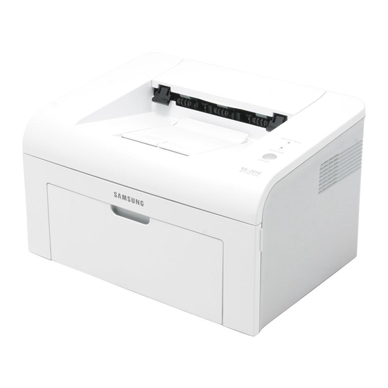
ML-2010
LASER PRINTER
ML-2010 Series
ML-2010/SEE
Basic Model : ML-2010
Manual
The keynote of Product
- Speed : 22ppm (Ltr) / 20ppm (A4),
600dpi 1200dpi
- Paper Path : MPF Type Cassette
- Emulation : SPL (ML-2010 / ML-2015)
- Processor : 150MHz Jupiter4e CPU
- Memory : 8MB
- Toner Cartridge : Initial (1K), Sales (3K)
- MP Cassette : 150 pages / Face Down
(50 pages)
- Manual Duplex : Manual Feed Guide
- Fuser Design : Lamp Type
- I/O : USB1.1
- Machine Life : 50K(pages)
Advertisement
Table of Contents

Related Manuals for Samsung ML-2010/SEE


Summary of Contents for Samsung ML-2010/SEE
- Page 1 LASER PRINTER ML-2010 Series ML-2010/SEE Basic Model : ML-2010 Manual SERVICE LASER PRINTER The keynote of Product - Speed : 22ppm (Ltr) / 20ppm (A4), 600dpi 1200dpi - Paper Path : MPF Type Cassette - Emulation : SPL (ML-2010 / ML-2015)
- Page 2 * This service manual is a property of Samsung Electronics Co., Ltd. Any unauthorized use of Manual can be punished under applicable international and/or domestic law. Samsung Electronics Co.,Ltd. May. 2005 * This service manual is also provided on the web, the ITSELF Printed in Korea.
-
Page 3: Table Of Contents
Contents 1. Precautions 1.1 Safety Warning 1.2 Safety Caution 1.3 ESD Precautions 2. Product Specification 2.1 Product Overview 2.2 Specifications 2.3 Model Comparison Table 3. System Overview 3.1 System Outline 3.2 H/W Structure and Descriptions 3.3 S/W Structure and Descriptions 3-19 3.4 Initial Product Installation 3-24... - Page 4 Continued 5. Disassembly and Reassembly 5.1 General Precautions on Disassembly 5.2 Disassembly and Reassembly 6. Troubleshooting 6.1 Checking Symptoms 6.2 Bad discharge 6.3 Malfunction 6.4 Bad software environment 6-13 6.5 Bad Image 6-17 7. Exploded Views & Parts List 7.1 Exploded Views and Parts List 8.
- Page 5 Continued 11. Reference Information 11.1 Troubleshooting Tools 11-1 11.2 Acronyms and Abbreviations 11-2 11.3 Selecting printer locations 11-4 11.4 Sample Tests Patterns 11-5 12. Circuit Description 12.1 Engine Controller 12-1...
-
Page 6: Precautions
Warning >> Never operate or service the printer with the protective cover removed from Laser/Scanner assembly. The reflected beam, although invisible, can damage your eyes. When using this product, these basic safety precautions should always be followed to reduce risk of fire, electric shock, and injury to persons. Service Manual Samsung Electronics... -
Page 7: Safety Caution
(12) Turn off the power and take off the plug when smoke, strange smell, or sound from the machine. If you keep using it, a fire can be occurred. (13) Do not insert steel or metal piece inside/outside of the machine. Do not put steel or metal piece into a ventila- tor. An electric shock could happened. Service Manual Samsung Electronics... - Page 8 (7) Be careful not to change the location of small parts such as screws when assembling and disassembling. (8) Do remove dust or foreign matters completely to prevent fire of tracking, short, or etc. (9) After finished repair, check the assembling state whether it is same as before the repair or not. Service Manual Samsung Electronics...
-
Page 9: Esd Precautions
9. Minimize bodily motions when handling unpackaged replacement ESDs. Normal motions, such as the brushing together of clothing fabric and lifting one’s foot from a carpeted floor, can generate static electricity sufficient to damage an ESD. Service Manual Samsung Electronics... -
Page 10: Product Specification
358 299 217 mm Weight Net : 4.8Kg(30.6Ib) with toner cartridge Gross : 7.65Kg(37.7Ib) Acoustic Noise Stand by : Less than 35 dB Printing : Less than 53 dB Power save mode Toner save mode Machine Life 50,000pages Service Manual Samsung Electronics... - Page 11 Configration Mode : Press the Demo Key for 2 Seconds Cleaning Mode : Not Support Service Mode : Press the Demo Key when Power on(F/W Download) ML-2015 model : I/O Support(USB 1.1 + IEEE 1284 Parallel port) Service Manual Samsung Electronics...
- Page 12 Starter: 1,000 Pages(initial) A4 Size, ISO 19752 Pattern Running : 3,000 Pages(sailes) 5% Coverage SIMPLEX Developing Method Non-magnetic Contact Developing Charging Method Conductive Roller Charging Toner Empty sensor Ozone 0.1PPM or less Cartridge Style Single cartridge Same as Service Manual Samsung Electronics...
- Page 13 C6 Env. 114 X 162(4.49 X 6.38") O(1 sheet) Transparency(OHP) A4 or Letter O(1 sheet) Label paper A4 or Letter O(1 sheet) 2.2.6.2 Input capacity Item Descriptions Tray 150 sheets 2.2.6.3 Output capacity 2.2.6.4 Duplex Printing Service Manual Samsung Electronics...
-
Page 14: Model Comparison Table
No. (New Drum Detection : No) No. (New Drum Detection : No) same Resolution 300 / 600dpi 600 / 1200dpi SPL Driver Unified UI Unified UI Manual Duplex Yes. Yes. Mech Manual Feeder Guide : Yes Manual Tray LED Green Service Manual Samsung Electronics... -
Page 15: System Overview
BIN PATH ❶ SMPS ❷ Fuser ❸ Toner Cartridge ❹ LSU ❺ Exit Roller ❻ OPC ❼ Pick-Up Roller ❽ KNOCK-UP PLATE ❾ KNOCK-UP PLATE DOWN ❿ ASS’Y HOLDER PAD Feed Sensor MAIN PBA SMPS HVPS Service Manual Samsung Electronics... - Page 16 System Overview Unit Layout Panel HVPS Motor SMPS Main PBA Service Manual Samsung Electronics...
- Page 17 Fuser/Exit 3.1.4 FUSER The fuser is consisted of the Heat Lamp,Heat Roller,Pressure Roller,Thermister and Thermostat. It adheres the toner on the paper with pressure and heat to complete the printing job. - Life Cycle : 50K(pages) Service Manual Samsung Electronics...
- Page 18 - 3st protecting device : Thermostat cuts off the power . Safety device - The power of Fuser is cut-off after front cover is open. - The overheating safety device for customer - The surface temperature of the Fuser Cover is under 80 Service Manual Samsung Electronics...
- Page 19 LSU to arrange the its margin on the paper. The one side of the polygon mirror is one line for scanning.. OPC Drum Photo Diode Polygon Mirror Polygon Motor Motor Driver LD Driver circit LD(Laser Diode) Protector panel Service Manual Samsung Electronics...
- Page 20 - Management of disusable toner: Collect the toner by using electric static (Clenerless Type- No disusable toner) - OPC Drum protecting Shutter: None - Classifying device for toner cartridge: ID is classified by interruption of the frame channel. Max -1.4KV Cleaning Blade -100V Cleaning Roller 0.20mW -720V -150V↓ -350V +5KV -550V Service Manual Samsung Electronics...
-
Page 21: H/W Structure And Descriptions
Main Control operate its full function on the Main B'd and CPU control Controller ASIC and build-in Memory. 3.2.1.2 CPU Use 32Bit RISC Processor of Jupiter4e, and control system by operating Operation Block of the System Program inside Flash Memory. Service Manual Samsung Electronics... - Page 22 - Left, Right Margin : 4.23 ° 3 mm 7) CRU(Toner Cartridge)Life : 2,000pages Printing(A4, 5% Pattern Printing) 8) First Print Out Time : within 11sec( Standby ) 9) Warming up time : within 30sec (Ambient : 25° Service Manual Samsung Electronics...
- Page 23 Main Board control to send Current Imagedml Video Data to LSU to print and have motor Driving and Circuit for the current driving and also include Paper Exit Sensor, Cover Open s/w, panel s/w. (IC-VOLTAGE COMP) (IC-CLOCK GENERATOR) 12.0MHz (IC-DRAM/ 512K x 16Bit) (IC-EEPROM/256x12Bit) (IC-POSI, ADSUST REG) (IC-CMOS LOGIC, INVER TER) (IC-POSI, FLXED REG) (IC-MOTOR DRIVER) Service Manual Samsung Electronics...
- Page 24 DC Motor connector(CN11) - It connects an main motor and drive a DC motor. HVPS connector(CN10) - It connects a HVPS. DCU connector(CN1) - It interface a DCU-JIG USB connector(CN6) - It interface a the printer. Service Manual 3-10 Samsung Electronics...
- Page 25 - Two external SDRAM attachable. - SDRAM controller supports PC-100 and PC-133 SDRAM running at 75MHz - Up to 32MB per bank. - Support for SDRAM configurations including programmable column address - Programmable refresh interval Service Manual 3-11 Samsung Electronics...
- Page 26 17. Miscellaneous - Mux controlled 24 GPI, 28 GPO & 5 GPIO ports . - Mutual exclusive GPO/GPIO ports control by the port control enable register - Programmable Bus Master Priority. - Project code added. Service Manual 3-12 Samsung Electronics...
- Page 27 M I SC ADC INTERFACE ADCIN3-0 TEST ( adc1275x_pc) OM2-0 nRESET PWM3-0 PW M PL L ( pll 2096x, pll 2073x) CAP2-0 CL O CK & RESET MOTPAT5-0 M O T O R C SCLK EXTCLK Service Manual 3-13 Samsung Electronics...
- Page 28 The solenoid consists of two used for paper pick-up and MP signal. D4 bit of CPU turns it on/off, and its driving time is 300ms. The diode protects the drive TR from the pulse (noise)generated by de-energizing operation of solenoid. Service Manual 3-14 Samsung Electronics...
- Page 29 SMPS has two output channels. Which are 5V and +24V Micro Switch CON1(Inlet) F1(Fuse/250V, 5A) Power Switch CON2 (Output) Exit Sensor Pin Signal <CON2> Pin No Pin Name +24VS2 +24V +24VS1 +24VS1 DGND DGND P_REGI FUSER ON Service Manual 3-15 Samsung Electronics...
- Page 30 . Running Current : under 40A PEAK (AT 25 , COLD START) under 50A PEAK (In other conditions) . Rising Time : within 2Sec . Falling Time : over 20ms . Surge : Ring Wave 6KV-500A (Normal, Common) Service Manual 3-16 Samsung Electronics...
- Page 31 - Output Voltage Fluctuation range: PWM Control - Input contrast of the output stability degree : 5 % or less - Loading contrast : 5 % or less - Output Voltage Rising Time : 50 ms Max Service Manual 3-17 Samsung Electronics...
- Page 32 - Output Loading range : 10 ~ 1000 - Output Control Signal (BIAS-PWM) : the CPU is HV output when PWM is low. LED2 (Toner Save LED) LED1 Switch (Error LED) Supply Micro Switch Input Service Manual 3-18 Samsung Electronics...
- Page 33 1) Triac (THY1) feature :16A, 600V SWITCHING 2) Phototriac Coupler (PC3) . Turn On If Current : 16mA . High Repetive Peak Off State Voltage : Min 600V Service Manual 3-19 Samsung Electronics...
-
Page 34: S/W Structure And Descriptions
- Control the Pick-Up, Feeding and Discharging of Paper - Control the LSU - Control the HVPS for the Developer Process - Control the Temperature of Fixing unit Controlling selection to here is added. - Second Cassette Feeder(SCF) : N/A Service Manual 3-20 Samsung Electronics... - Page 35 Main F/W of the printer controller Initial Engine F/W Device Units Fixing Unit Interface Control Module HVPS Engine Main Control Module Fan Unit Motors Solenold & Sensing & Unit Control Module Clutch Hardware Devices & Mechanical Device Service Manual 3-21 Samsung Electronics...
- Page 36 The third one is a fan control function that controls the fan unit. And the last one sets the flag that describes the present status of each sensor. Service Manual 3-22 Samsung Electronics...
- Page 37 (Tempe rature, .. ) Control the fi xing unit & Check error condition for the fixing un it Control the fan unit Get status value of each sensor & Set present status f lag of each sensor Service Manual 3-23 Samsung Electronics...
- Page 38 1 second. LSU Error LReady Error All LEDs (Toner save LED, Ready LED) blink a time interval of 1 second. Hsync Error All LEDs (Toner save LED, Ready LED) blink a time interval of 4 seconds. Service Manual 3-24 Samsung Electronics...
-
Page 39: Initial Product Installation
Remove the printer and all accessories from the packing carton. Make sure that the printer has been packed with the following items: 3.4.2 Installing the Toner Cartridge 1. Grasp the front cover and pull it toward you to open. Service Manual 3-25 Samsung Electronics... - Page 40 2. Remove the toner cartridge from its bag and remove the paper covering the cartridge. 3. Gently shake the cartridge from side to side to distribute the toner evenly inside the cartridge. 4. Locate the cartridge slots inside the printer, one on each side. Service Manual 3-26 Samsung Electronics...
- Page 41 5. Unfold the toner cartridge handle and grasp it. Insert the cartridge in the printer until it snaps into place. 6. Close the front cover. Make sure that the cover is securely closed. If the cover is not firmly closed, printing errors may occur when you print. Service Manual 3-27 Samsung Electronics...
- Page 42 2. Prepare a stack of paper for loading by flexing or fanning them back and forth. Straighten the edges on a level surface. 3. Load paper with the print side facing up. Make sure that all four corners are flat in the tray. Service Manual 3-28 Samsung Electronics...
- Page 43 2. Plug the USB printer cable into the connector on the back of the printer. 3. Connect the other end of the cable to the USB port on your computer. See your computer User’s Guide if you need help. Service Manual 3-29 Samsung Electronics...
- Page 44 Print a demo page to make sure that the printer is operating correctly. 1. Press and hold down the Cancel button on the control panel for about 2 seconds to print a demo page. 2. The Demo page shows the printer’s current configuration. Service Manual 3-30 Samsung Electronics...
- Page 45 Pentium II 933 Ghz or higher Window 98/Me/2000 64 MB or higher Window XP 128 MB or higher Free Disk Space Window 98/Me/2000 300 MB or higher Window XP 1 GB or higher Internet Explorer 5.0 of higher Service Manual 3-31 Samsung Electronics...
-
Page 46: Alignment And Adjustments
USB 1.1 interfaces: ML-2010 Series www.samsungprinter.com e v e r y o n e ’ s i n v i t e d **AII other trademarks are the property of their respective owners. Samsung Electronics, AII rights reserved. Service Manual Samsung Electronics... -
Page 47: Control Panel
If you press the Cancel button in Ready mode, this LED is on and the Toner Save mode is enabled. If you press this button once again, this LED is off and the Toner Save mode is disabled. If the On Line/Error and Toner Save LEDs blink, your system has some problems. Service Manual Samsung Electronics... - Page 48 Ready mode. This may take some time depending on the size of the print job. In Manual Feed mode, you can’t cancel the print job by pressing this button. Toner Save mode on/off In Ready mode, press this button to turn the Toner Save mode on or off. Service Manual Samsung Electronics...
-
Page 49: Consumables And Replacement Parts
(Pmotor Error) simultaneously flashing every one-second. LSU Not Ready Error The printing is stop in the fad status, and the [Error] LED (green) and (HSYNC Error) the [Toner Save] LED are simultaneously flashing every 4 seconds. Service Manual Samsung Electronics... -
Page 50: Periodic Defective Image
Transfer Roller 46.2mm image ghost Heat Roller 63.9mm Black spot and image ghost Pressure Roller 75.4mm black spot on the backside BIN PATH Transfer Roller OPC Drum Heat Roller Charge Roller Pressure Roller Supply Roller Developing Roller Service Manual Samsung Electronics... -
Page 51: How To Use Dcu
COVER OPEN ERROR NO PAPERR PAPER JAM 0 PAPER JAM 1 PAPER JAM 2 LSU NOT READY DIAGNOSTIC DOWN SHIFT STOP MODE ENTER TO ENTER DIAGNOSTIC MODE, PUSH THREE BUTTONS SIMUL ANEOUSL AND TURN THE PRINTER POWER ON. Service Manual Samsung Electronics... - Page 52 The front part of paper is jammed just after passing through the discharge sensor. Out Bin Full The Out bin is filled with paper. LSU Not Ready LSU Scanner Motor not ready or Hsync signal not output. Service Manual Samsung Electronics...
- Page 53 [Up] button to Check LD. LD is functioning and the middle button is on. If the LD is normal, all LEDs are on. Pickup clutch on The Solenoid in the printer is in operation. To stop the operation, Press the button [shift] and [Enter] together. Service Manual Samsung Electronics...
- Page 54 Indicates the function of the Fan, same method of the code ‘07’. Manual Pickup Test : Indicates the function of th Manual Pickup, same method of the code ‘07’. Manual Sensor Test : Indicates the function of the Manual Sensor, same method of the code ‘07’. Service Manual Samsung Electronics...
- Page 55 READY Mode, and '88' shows in the DCU. In this mode, without any detection, the printer begins printing(trial printing and data from the PC). It is convenient to use this mode when the engine malfunction is detected in the control board. Service Manual 4-10 Samsung Electronics...
-
Page 56: Paper Path
4) The paper passed the paper exit sensor moves out from the set. (Jam 2 occurs sometime after if the tailing edge of the paper is not coming out from the set after the leading edge of paper passes the paper exit sensor.) BIN PATH BIN PATH BIN PATH Service Manual 4-11 Samsung Electronics... - Page 57 When you pull the jammed paper, if there is resistance and the paper does not move immediately, stop pulling. Continue with the next step. 2. Open the top cover and the inner cover. H eat roller Service Manual 4-12 Samsung Electronics...
- Page 58 3. Loosen the paper if it is caught in the heat rollers. Then pull the paper gently out. 4. Close the inner cover and the top cover. 5. Open and close the front cover. Printing can be resumed. Service Manual 4-13 Samsung Electronics...
- Page 59 1. Remove any missfeed paper by pulling it out by the visible edge from the tray. Make sure that all of the paper is properly aligned in the tray. 2. Open and close the front cover. Printing can be resumed. 4.7.4 Around the Toner Cartridge 1. Open the front cover. Service Manual 4-14 Samsung Electronics...
- Page 60 2. Pull the toner cartridge out and remove it from the printer. 3. Gently pull the paper toward you. 4. Check that there is no other paper in the printer. 5. Reinstall the toner cartridge, and then close the cover. Printing can be resumed. Service Manual 4-15 Samsung Electronics...
- Page 61 • Clean the inside of the printer • Adjust the print resolution from the printer properties • Ensure that the Toner Save mode is off • Clear general printing problems • Install a new toner cartridge, and check the print quality Service Manual 4-16 Samsung Electronics...
-
Page 62: Disassembly And Reassembly
3. Unplug the power cord. 4. Use a flat and clean surface. 5. Replace only with authorized components. 6. Do not force plastic-material components. 7. Make sure all components are in their proper position. Service Manual Samsung Electronics... - Page 63 2. Separate the cover from the lock of the frame by tray are assembled with the same assembly.) pulling the right bottom of the cover toward the arrow direction. Pull out the front cover to the left as shown as below. Cassette Tray Front Cover Service Manual Samsung Electronics...
- Page 64 Disassembly and Reassembly 5.2.2 MP Tray 1. Open the front cover. 3. Hold the MP Tray and pull it to the arrow direction. MP Tray 2. Release the Toner Cartridge. Toner Cartridge Service Manual Samsung Electronics...
- Page 65 2. Separate the lock by holding the left side of the cover (Screw x2:Silver_M3,6003-000196) and pulling it toward the arrow direction. Remove it with carefulness that the power switch is not hooked on SMPS cover as shown as below. SMPS Cover Service Manual Samsung Electronics...
- Page 66 5. If necessary,remove the jam cover.Open the cover, toward the arrow direction as shown as below. take out the hook on the right toward the arrow direc- tion, and then take out the jam cover to the right side. Jam Cover Service Manual Samsung Electronics...
- Page 67 4 locks on the front and rear of the top cover by using a screw driver.Remove the top cover from the main cover. (Screw x 5:Silver_M3,6003-000196) Top Cover On-Line Key LED Lens Main Cover Service Manual Samsung Electronics...
- Page 68 -Separate the Main cover.(Refer to 5.4) 2. Remove the sheet by releasing the 5 screws which connects the HVPS and the Sheet. (Screw x 3:Gold_M3,6003-000269) HVPS Ground HVPS HVPS Sheet 4. Remove the connector from the separated HVPS. Service Manual Samsung Electronics...
- Page 69 3. Remove the connector from the separated RX drive. Gear Bracket RX Drive RX Motor Motor Bracket Note: Please, be careful not to touch the protruding 4 screws at the out- side of the RX drive. Service Manual Samsung Electronics...
- Page 70 F/Down to the arrow direction.At this time,roller_main,roller_FR, F/Down Holder,and spring are separated with theses. Exit Gear Exit Roller F/Down Roller_FR 3. Separate the fuser by unscrewing 4 screws on the Holder Roller_Main frame. (Screw x 4:Gold_M3,6003-000269) F/Down Holder Fuser Service Manual Samsung Electronics...
- Page 71 Note : Under the condition that the fuser is connected to the frame,the exit roller F/Down can be separated.However,be careful that the Roller_Main,the Roller_FR,and F/Down Holder could get into the inner frame due to the spring’ action. Service Manual 5-10 Samsung Electronics...
- Page 72 (Screw x 3 : Gold_M3, 6003-000269) harnesses from the shield,and then separate the engine shield with carefulness of the actuator feed Main PBA sensor lever. (Screw x 6:Silver_M3,6003-000196) Engine Shield (W/Main PBA, SMPS) Actuator Feed Sensor Lever Service Manual 5-11 Samsung Electronics...
- Page 73 2. Release 3 screws as shown as below, lift up the LSU, -Separate the font cover.(Refer to 5.2) and then disconnect 2 connectors from the separated -Separate the SMPS cover.(Refer to 5.3) LSU. (Screw x 2:Silver_M3,6003-000196) -Separate the Main cover.(Refer to 5.4) Service Manual 5-12 Samsung Electronics...
- Page 74 Bush ground and harnesses. (Screw x 4:Silver_M3,6003-000196) Transfer Roller Bush(L) 4. Remove the solenoid-MP by releasing the screw from the left side of the frame. (Screw x 1:Gold_M3,6003-000301) Paper Path Frame Mirco S/W Solenoid-MP Service Manual 5-13 Samsung Electronics...
- Page 75 2. While pressing the hooks on the left/right side of the front cover, and then take out the toner cartridge. pick-up housing B, pull out the pick-up housing U as shown as below.Then,replace the sponge. Housing B Toner Cartridge Sponge Housing U Service Manual 5-14 Samsung Electronics...
-
Page 76: Troubleshooting
Power On - No Power On-Line LED - Power Module error - Main PBA Indicate Refer to On-Line LED Green OK? "Lamp toggle" "Chapter 4.4" Print(test pattern) printing Refer to "Solution Quality is of Image Problem" Nomal? Service Manual Samsung Electronics... - Page 77 --> Refer to section 6.5 (Page 6-17). 6. Check consumables (toner etc.). •Using the keys print the Test Pattern. --> Expected life of various consumable parts, compare this with the figures printed and replace as required Service Manual Samsung Electronics...
- Page 78 1. Use only paper which is of a suitable quality, weight and size? See the user guide. 4. Check the overall condition of the printer 1. Is the printer properly maintained ? Clean the Paper Transport Passages. Any rollers with dirt surfaces should be cleaned or replaced. Service Manual Samsung Electronics...
-
Page 79: Bad Discharge
3. Clean with soft cloth dampened with IPA(Isopropyl ter. Alcohol) or water. 4. If the paper feeds into the printer rand Jam 0 occurs, 4. Replace the SMPS, HVPS or Sensor. perform DCU to check feed-sensor of the engine board. Service Manual Samsung Electronics... - Page 80 3. Remove the jammed paper after disassembling the fuser : Clean the surface of the pressure roller with dry gauze. • Remove the toner particles stained on the rib. • Check the assemblage and performance of the exit. Service Manual Samsung Electronics...
- Page 81 2. If there is heavy background, repair it by the ted. background troubleshooting method. 3. The surface of the heat roller with IPA or water 4. Check the warp or separation of the sprint claw and the holder plate claw, and then man- age it. Service Manual Samsung Electronics...
- Page 82 1. Recommend to use normal paper. 2. The face of paper is curled. 2. How to remove the rolled in the OPC Drum. • Remove the paper while turning the OPC Drum against the ongoing direction. Service Manual Samsung Electronics...
-
Page 83: Malfunction
Check and Cause Solution DCU Mode : Perform DCU diagnostic code 05. If the DCU Replace LSU. error code 95 is displayed, replace LSU. If you cannot solve the problem after you replace LSU, replace the main board. Service Manual Samsung Electronics... - Page 84 1. Bending or deformation of the actuator of the paper sen- 1. Replace the defective actuator. sor. 2. The function of the engine board is defective Perform. 2. Replace the engine board. DCU mode : Perform DCU diagnostic code 8. Service Manual Samsung Electronics...
- Page 85 Main Control board. Perform DCU Connect. mode : If Error state '64' occurs, Check the related codes of the Cover Open Error 2. Replace the Main Control board or Cover Open S/W. Service Manual 6-10 Samsung Electronics...
- Page 86 1. Replace the power supply cord or SMPS. 2. Check the inferiority of LED-Panel on the front-cover if 2. Replace the control board. the LED of Panel does not appear after normal warming- 3. Replace the LED-panel. Service Manual 6-11 Samsung Electronics...
- Page 87 1. If the supply of +24v is unstable in the Main Control board 1. Replace LSU. linking with LSU, check drive by DCU Mode : LSU Check -05- LSU Motor on. 2. Replace the Main Control board. Service Manual 6-12 Samsung Electronics...
-
Page 88: Bad Software Environment
4. If the scanner needs to be connected to the printer, 4. Check if the printer cable is directly connected to periph- first the remove the scanner from the PC to see if the eral devices printer is properly working alone. Service Manual 6-13 Samsung Electronics... - Page 89 Turn the PC and printer off, and reboot the system to print again. If not solved, double-click the printer in my computer If the regular fonts are not printed this time again. the cable must be defective so replace the cable with new one. Service Manual 6-14 Samsung Electronics...
- Page 90 3. Delete the unnecessary files to secure enough (The printing job sometimes stops or due to insufficient space of the hard disk and start printing job again. virtual memory, but it actually comes from the insuffi- cient space of the hard disk.) Service Manual 6-15 Samsung Electronics...
- Page 91 Before choosing the document, the menu is still inactive. Or put the document out of the list and repeat the routine as in the above or finish the spool manager. Service Manual 6-16 Samsung Electronics...
-
Page 92: Bad Image
4. No. 4. : Open the front cover and check odically at the top of a black image. ribs that corresponds to the position of the voids. Remove if found. 5. If the problems are not solved, replace the developer cartridge. Service Manual 6-17 Samsung Electronics... - Page 93 1, take measures as to replace the develop- er cartridge and try to print out. 5. Clean the inside of the set against the paper particles and foreign matter in order not to cause the trouble. Service Manual 6-18 Samsung Electronics...
- Page 94 HVPS. in the side of the Developer and charge terminal of HVPS. 3. Replace the HVPS if not solved by the above direction 1 and 2. Service Manual 6-19 Samsung Electronics...
- Page 95 4. Is the movement(Up and Down) of 4. Clean the bushing part of the transfer the transfer roller smooth? roller. 5. Is the HVPS normal? 5. If the problem is still not solved, replace the developer. Service Manual 6-20 Samsung Electronics...
- Page 96 Digital Printer mal paper or transparencies such as OHP, the software application and after using return- Digital Printer higher transfer voltage is required. ing to the original mode is recommended. Digital Printer Digital Printer Digital Printer Service Manual 6-21 Samsung Electronics...
- Page 97 2. If the transfer roller is contaminated, run PC on the face of page will occur. Cleaning Mode Print 2 or 3 times. Digital Printer And perform Self-Test 2 or 3 times to remove contamination. Service Manual 6-22 Samsung Electronics...
- Page 98 Solenoid is normal.(refer to code 06) 3. If not solved by the above directions 1-2, Replace the engine board. 4. Turn the power off, delete the data of PC and try printing again. Service Manual 6-23 Samsung Electronics...
-
Page 99: Exploded Views & Parts List
This format is used throughout Samsung on all product ranges. Typically it is used for small components and electronic parts. This format is controlled by individual Samsung Divisions and is used on specific products, typically for mechanical parts. Type 2 format part numbers fall into 2 categories: Assemblies consisting of 2 or more parts. - Page 100 Exploded Views & Parts List 7.1 Main Assembly 15-1 15-2 Service Manual Samsung Electronics...
- Page 101 JC44-00079A HVPS-SKYLARK 7.1-17 D2132 JC63-00722A SHEET-HVPS 7.1-18 K3232 JC63-00631A GROUND-P-HVPS 7.1-19 K2903 3903-000085 CBF-POWER CORD, 110V 7.1-19 K2903 3903-000042 CBF-POWER CORD, 220V 7.1-20 P5151 JC61-01170A PLATE-P-CHANNEL 7.1-21 T4044 JC97-02239A MEA UNIT-MP TRAY 7.1-22 F5019 JC31-00027A FAN-DC_HUMMINGBIRD Service Manual Samsung Electronics...
- Page 102 Exploded Views & Parts List 7.2 Frame Assembly Service Manual Samsung Electronics...
- Page 103 GEAR-FUSER DR 63/35 7.2-14 F6076 JC66-00808A GEAR-FEED DR 41 7.2-15 K3816 JC66-00822A LEVER-M-ACTUATOR_EMPTY 7.2-16 Z4274 JB61-00076A SPRING ETC-TORSION DOC (CC2-F);SCX-1110F 7.2-17 D4053 JC63-00622A GROUND-P-OPC 7.2-18 D4084 6107-001240 SPRING-CS 7.2-19 A0003 JC67-00110A CAP-M-MOTOR 7.2-20 B2030 JC61-00025A SPRING-CS-CHARGE APOLLO;SF-5100 Service Manual Samsung Electronics...
- Page 104 Exploded Views & Parts List 7.3 Fuser Unit Service Manual Samsung Electronics...
- Page 105 E4039 JC66-00801A GEAR-EXIT_DR38/25 7.3-27 S2004 6031-001051 WASHER-PLAIN;M4,ID4.1,OD7.0,T0.1 7.3-28 D4086 6107-001163 SPRING-CS;SUS304-WPB,-,PI0.4,D3.9,L13,-, 7.3-29 Z2194 JC63-00637A COVER-M-FUSER-DUMMY 7.3-30 L1014 JC63-00639A COVER-M-LAMP-L 7.3-31 L1015 JC63-00638A COVER-M-LAMP-R 7.3-32 D4088 6044-000001 RING-CS;ID3,OD3,T0.25,BLACK,SUS304 7.3-33 E4159 JC66-00826A ROLLER-EXIT F/DOWN 7.3-34 H4087 JC67-00085A CAP-M-THERMO Service Manual Samsung Electronics...
- Page 106 Exploded Views & Parts List 7.4 Paper Path Unit 11-3 11-2 11-1 Service Manual Samsung Electronics...
- Page 107 IPR-P-EARTH TRANSFER;ML-1710,S 7.4-20 P2160 JC66-00829A SHAFT-P-PICK_UP;ML-1610,SECC,2 7.4-21 P2067 JC61-01151A HOUSING-M-PICK_U;ML-1610,POM,- 7.4-22 P2068 JC61-01173A HOUSING-M-PICK_UP B;ML-1610,AB 7.4-23 P2148 JC73-00211A RUBBER-PICK_UP;ML-1610,EPDM+IR 7.4-24 P2042 JC66-00811A CAM-M-PICK_UP;ML-1610,POM,4,W2 7.4-25 G0448 JC66-00813A GEAR-TRANSFER;ML-1610,POM,0.6, 7.4-26 JC61-01281A BRACKET-P-BAR_PICK-UP; 7.2-27 Z8003 JC39-00482A CBF HARNESS-MICRO SW Service Manual Samsung Electronics...
- Page 108 Exploded Views & Parts List 7.5 MP Tray Assembly Service Manual 7-10 Samsung Electronics...
- Page 109 Location MP Tray Assembly Exploded View Parts List 7.5-0 T4044 JC97-02239A MEA UNIT-MP-TRAY 7.5-1 P5146 JC61-01263A PLATE-M_MP 7.5-2 K2008 JC70-00514A ADJUST-M_MP L 7.5-3 K2009 JC70-00515A ADJUST-M_MP R 7.5-4 G0369 JG66-40003A GEAR-PINION 7.5-5 G2152 JC63-00711A SHEET-MP Service Manual 7-11 Samsung Electronics...
- Page 110 Block diagram 8. Block Diagram 8.1 ML-2010(20ppm GDI_USB Only) H/W Block Diagram Service Manual Samsung Electronics...
- Page 111 Block diagram 8.2 ML-2015(20ppm GDI P1284) H/W Block Diagram Service Manual Samsung Electronics...
- Page 112 Connection Diagram 9. Connection Diagram Service Manual Samsung Electronics...
- Page 113 Schematic Diagram 10. Schematic Diagrams 10.1 Main Board(1/5) Service Manual 10-1 Samsung Electronics This Document can not be used without Samsung’s authorization.
- Page 114 Schematic Diagram Main Board(2/5) Service Manual 10-2 Samsung Electronics This Document can not be used without Samsung’s authorization.
- Page 115 Schematic Diagram Main Board(3/5) Service Manual 10-3 Samsung Electronics This Document can not be used without Samsung’s authorization.
- Page 116 Schematic Diagram Main Board(4/5) Service Manual 10-4 Samsung Electronics This Document can not be used without Samsung’s authorization.
- Page 117 Schematic Diagram) Main Board(5/5) Service Manual 10-5 Samsung Electronics...
- Page 118 Schematic Diagram 10-2 Connector Circuit Diagram Service Manual 10-6 Samsung Electronics This Document can not be used without Samsung’s authorization.
- Page 119 Schematic Diagram 10-3 SMPS Circuit Diagram Service Manual 10-7 Samsung Electronics This Document can not be used without Samsung’s authorization.
- Page 120 Schematic Diagram 10-4 HVPS Circuit Diagram(1/3) Service Manual 10-8 Samsung Electronics This Document can not be used without Samsung’s authorization.
- Page 121 Schematic Diagram HVPS Circuit Diagram(2/3) Service Manual 10-9 Samsung Electronics This Document can not be used without Samsung’s authorization.
- Page 122 Schematic Diagram 10-4 HVPS Circuit Diagram(3/3) Service Manual 10-10 Samsung Electronics This Document can not be used without Samsung’s authorization.
- Page 123 • Spring Hook Standard : For general use • Tweezers Standard : For general home use, small type. • Cotton Swab Standard : For general home use, for medical service. • Software (Driver) installation CD ROM Service Manual 11-1 Samsung Electronics...
- Page 124 Host Based Printing Hard Disk Drive High temperature and high marshy place high voltage HVPS High Voltage Power Supply interface Input and Output integrated circuit Intelligent Drive electronics or Imbedded Drive Electronics Service Manual 11-2 Samsung Electronics...
- Page 125 Quick Printer Initiating Device Q ty quantity Random Access Memory Read Only Memory Second Cassette Feeder SMPS Switching Mode Power Supply SPGP Samsung Printer Graphic Processor Samsung Printer Language Spool Simultaneous Peripheral Operation Online switch sync synchronous or synchronization Universal Serial Bus WECA...
- Page 126 • Provide the proper environment : - A firm, level surface - Away from the direct airflow of air conditioners, heaters, or ventilators - Free of extreme fluctuations of temperature, sunlight, or humidity - Clean, dry, and free of dust Service Manual 11-4 Samsung Electronics...
- Page 127 The life of the toner cartridge, developer cartridge and printing speed are measured with the pattern shown below (5%). The A4 ISO 19752 standard pattern samples are reproduced reduced to 70% of the actual A4 size. A4 ISO 19752 Standard Patterns Service Manual 11-5 Samsung Electronics...
- Page 128 TRIAC. Consequently, the heat lamp is turned off. Special Feature of TRIAC (THY 1): 16A, 600V SWITCHING Phototriac Coupler (PC3) Turn On If Current: 15mA~50mA (Design: 16mA) High Repeive Peak Off State Voltage: Min 600V Service Manual 12-1 Samsung Electronics...
- Page 129 Circuit Description Service Manual 12-2 Samsung Electronics...
- Page 130 The entire diagram of the PWMTIMER is organized as below. PWM TIMER OPERATION is figured out if calculating PHCLK by the value selected by the register setting and the divider. PHCLK is created by count block at the PWM TIMER Service Manual 12-3 Samsung Electronics...
- Page 131 It is three layer filter, and the delay time is 3*System Clock Time. The interface between PVC and LSUC is shown in the picture. LSUC LSU_VDO nHSYNC LSU_VDO nHSYNC PVC_VDO nPSync PVC_TEST_EN nLSYNC PVC_TEST_EN nFSYNC nFSYNC Service Manual 12-4 Samsung Electronics...
- Page 132 PRDATA[31:0] DAC_OUT APCCON[11:0] nPSync apcOnTime[20:0] apcOffTime[20:0] THER Pmax[9:0] Control Pmin[9:0] Bl ock Ka[14:0] REF[24:0] Kp[15:0] Ki[4:0] CKIN. ADC_EN SEL[1:0] YMAXH[8:0] YMAXL[31:0] YMINH[8:0] ADO_2[9:0] YMINL[31:0] YINITH[8:0] Cont roller YINITL[31:0] KU[5:0] U_VALUE[25:0] SEH[4:0] SEL[4:0] L_VAL UE[9:0] HCLR[20:0] Service Manual 12-5 Samsung Electronics...
- Page 133 STC of the register. After finishing the conversion, it makes the interrup- tion to be pending. When AD conversion of 3 rd channel ends for the PI Control of LSU, it sends the 10bit digital data converted with the latch short pulse signal to LSUC. Service Manual 12-6 Samsung Electronics...