Table of Contents
Advertisement
Quick Links
Use
Functions
Basic functions
Rotational movement
Three-position control
Fail-safe function
Position indication
Manual override
Siemens Building Technologies
Landis & Staefa Division
TM
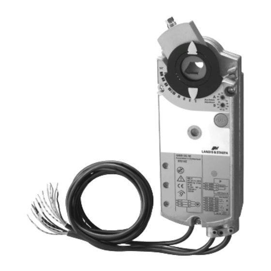
OpenAir
Air damper actuators
Rotary version three-position control
AC 24 V or AC 230 V
Electromotive rotary actuators for three-position control, nominal torque 35 Nm,
operating voltage AC 24 V or AC 230 V, for three-position control, span
mechanically adjustable between 0...90°, pre-wired with 0.9 m long connection
cables.
Type-specific variations with adjustable auxiliary switches for supplementary
functions and potentiometer for position indication.
To control air dampers in ventilating and air conditioning plants
• using a nominal torque of 35 Nm for damper surfaces up to 6 m
•
Ideal with modulating three-position controllers or ON/OFF-controls (e.g., outside air
dampers, flue gas dampers, etc.)
The actuator's rotational movement (clockwise or counterclockwise) depends on the
electrical control.
As soon as the operating voltage AC 24 V or AC 230 V is applied, the actuator starts to
turn.
The connected damper can be operated as follows via the respective actuator control:
•
Damper opens (0° ⇒ 90°)
•
Damper closes (90° ⇒ 0°)
• Damper remains in the current position
After uninterrupted runtime of approximately 200 s, the actuator turns off in the same
direction.
The position indicator located on the shaft adapter displays the rotational angle position
of the damper blade.
To manually adjust the actuator or the air dampers, the gear train must be disengaged
using the button PUSH". Refer to "Operating and setting elements" in the chapter
"Mechanical design".
625
4
GIB13...1
GIB33...1
2
, friction-dependent
CM2N4625E / 02.1999
1/10
Advertisement
Table of Contents

Related Manuals for Siemens OpenAir GIB13.1 Series


Summary of Contents for Siemens OpenAir GIB13.1 Series
- Page 1 To manually adjust the actuator or the air dampers, the gear train must be disengaged using the button PUSH". Refer to "Operating and setting elements" in the chapter "Mechanical design". Siemens Building Technologies CM2N4625E / 02.1999 Landis & Staefa Division...
-
Page 2: Technical Design
AC 24 V or AC 230 V. Technical design Motor technology The reversible synchronous motor provides accurate speed control and nominal force monitoring to protect the actuator and dampers. CM2N4625E / 02.1999 Siemens Building Technologies 2/10 Landis & Staefa Division... -
Page 3: Mechanical Design
Potentiometer for A potentiometer has been integrated as positioner for the electrical position indication of position indication the damper position. Siemens Building Technologies CM2N4625E / 02.1999 Landis & Staefa Division 3/10... - Page 4 A and B Position indicator Self-centering shaft adapter Locking ring for shaft adapter Adapter for position indicator Mounting bracket Arrangement for long shaft adapters Arrangement for short shaft adapters CM2N4625E / 02.1999 Siemens Building Technologies 4/10 Landis & Staefa Division...
-
Page 5: Engineering Notes
Determine the transformer’s power consumption by adding the power consumption in VA for all actuators used. Wiring and Refer to "Commissioning notes" and "Internal diagram" in this data sheet as well as to commissioning the HVAC job drawings. Siemens Building Technologies CM2N4625E / 02.1999 Landis & Staefa Division 5/10... -
Page 6: Mounting Notes
Check to ensure that the cables are connected in accordance with the plant wiring diagram (see "Diagrams"). • The operating voltage AC 24 V (SELV/PELV) or AC 230 V must be within the tolerance values. CM2N4625E / 02.1999 Siemens Building Technologies 6/10 Landis & Staefa Division... -
Page 7: Technical Data
Power supply AC 24 V (wires 1, 6, 7) / AC 230 V (wires 4, 6, 7) 3 x 0.75 mm Connection cables 6 x 075 mm Auxiliary switches A and B (wires S1...S6) 3 x 0.75 mm Potentiometer (wires P1, P2, P3) Siemens Building Technologies CM2N4625E / 02.1999 Landis & Staefa Division 7/10... -
Page 8: Internal Diagrams
AC 24 V 0...1000 Ω AC 230 V AC 24 V...230 V / 6 (2) A GIB331.1E AC 230 V GBB33... GIB335.1E P1 P2 GIB33... GIB336.1E 100% S2 S3 S5 S6 CM2N4625E / 02.1999 Siemens Building Technologies 8/10 Landis & Staefa Division... -
Page 9: Connection Diagrams
AC 230 V GIB335.1E GIB336.1E (Y1) (Y2) P1 P2 GBB33... Regulator or controller Actuator GIB33..., S2 S3 S5 S6 three-position, AC 230 V Phase conductor AC 230 V Neutral conductor Siemens Building Technologies CM2N4625E / 02.1999 Landis & Staefa Division 9/10... - Page 10 1...7 GIB...1 S1...S6 Ø 8... 25,6 mm 6... 18 mm min. 100 Taptite ø M6 x 16 min. 60 4626M01 1999 Siemens Building Technologies Ltd. Dimensions in mm CM2N4625E / 02.1999 Siemens Building Technologies 10/10 Landis & Staefa Division...