Table of Contents
Advertisement
Quick Links
SAFETY PRECAUTION FOR SERVICE MANUAL ........................................................................................................... 2
IMPORTANT SERVICE NOTES (FOR U.K. ONLY) .......................................................................................................... 2
SPECIFICATIONS ............................................................................................................................................................. 3
NAMES OF PARTS ........................................................................................................................................................... 4
OPERATION MANUAL ..................................................................................................................................................... 6
QUICK GUIDE (FOR U.K. ONLY) ...................................................................................................................................... 7
DISASSEMBLY .................................................................................................................................................................. 9
REMOVING AND REINSTALLING THE MAIN PARTS ................................................................................................... 12
ADJUSTMENT ................................................................................................................................................................. 13
NOTES ON SCHEMATIC DIAGRAM .............................................................................................................................. 19
WAVEFORMS OF CD CIRCUIT ...................................................................................................................................... 20
BLOCK DIAGRAM ........................................................................................................................................................... 21
SCHEMATIC DIAGRAM / WIRING SIDE OF P.W.BOARD .............................................................................................. 24
VOLTAGE ........................................................................................................................................................................ 42
TROUBLESHOOTING ..................................................................................................................................................... 43
FUNCTION TABLE OF IC ................................................................................................................................................ 47
FL DISPLAY ...................................................................................................................................................................... 53
WIRING OF PRIMARILY SUPPLY LEADS (FOR U.K. ONLY) ........................................................................................ 54
REPLACEMENT PARTS LIST/EXPLODED VIEW
SERVICE MANUAL
CONTENTS
SHARP CORPORATION
- 1 -
CD-BA2000H
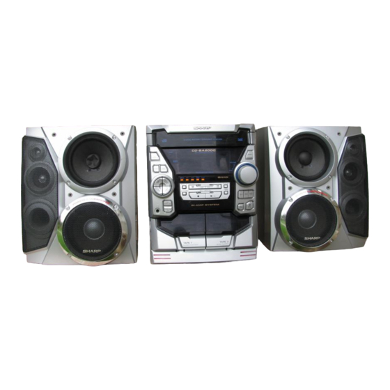
CD-BA2000H Mini Component System consisting of
CD-BA2000H (main unit) and CP-BA2000H (speaker system).
• In the interests of user-safety the set should be restored to its
original condition and only parts identical to those specified be
used.
• Note for users in U.K.
Recording and playback of any material may require consent
which SHARP is unable to give. Please refer particularly to the
provisions of Copyright Act 1956, the Dramatic and Musical
Prefomers Protection Act 1956, the Preformers Protection Acts
1963 and 1972 and to any subsequent statutory enactments and
orders.
This document has been published to be used
for after sales service only.
The contents are subject to change without notice.
CD-BA2000H
No. S3020CDBA2000
Page
Advertisement
Table of Contents

Related Manuals for Sharp CD-BA2000H


Summary of Contents for Sharp CD-BA2000H
-
Page 1: Table Of Contents
• Note for users in U.K. Recording and playback of any material may require consent which SHARP is unable to give. Please refer particularly to the provisions of Copyright Act 1956, the Dramatic and Musical Prefomers Protection Act 1956, the Preformers Protection Acts 1963 and 1972 and to any subsequent statutory enactments and orders. -
Page 2: Safety Precaution For Service Manual
CD-BA2000H (For U.K.) SAFETY PRECAUTION FOR SERVICE MANUAL Precaution to be taken when replacing and servicing the Laser Pickup. The AEL (Accessible Emission Level) of Laser Power Output for this model is specified to be lower than Class I Requirements. -
Page 3: Specifications
CD-BA2000H FOR A COMPLETE DESCRIPTION OF THE OPERATION OF THIS UNIT, PLEASE REFER TO THE OPERATION MANUAL. SPECIFICATIONS CD-BA2000H General Cassette deck section Power source: AC 230 V, 50 Hz Frequency response: 50-14,000 Hz (Normal tape) Power consumption: 154 W... -
Page 4: Names Of Parts
CD-BA2000H NAMES OF PARTS CD-BA2000H Front panel (CD) Disc Tray Extra Bass Indicator Spectrum Analyzer/Volume Level Indicator (CD) Disc Number Indicators (CD/TUNER) Memory Indicator (TAPE 2) Record Indicator (CD) Play Indicator (CD) Music Schedule Indicators (CD) More Tracks Indicator (CD) Random Play Indicator... - Page 5 CD-BA2000H Rear panel AC Power Lead FM 75 Ohms Aerial Socket AM Loop Aerial Socket Speaker Terminals Video/Auxiliary (Audio Signal) Input Sockets CP-BA2000H Speaker Super Tweeter Tweeter Bass Reflex Duct Woofer Subwoofer Main Speaker (Woofer, Tweeter and Super Tweeter) Wire...
-
Page 6: Operation Manual
CD-BA2000H OPERATION MANUAL – 6 –... -
Page 7: Quick Guide (For U.k. Only)
CD-BA2000H – 7 –... - Page 8 CD-BA2000H – 8 –...
-
Page 9: Disassembly
CD-BA2000H DISASSEMBLY CD-BA2000H Caution on Disassembly Follow the below-mentioned notes when disassembling (A1)x2 Top Cabinet the unit and reassembling it, to keep it safe and ensure ø3x12mm excellent performance: 1. Take cassette tape and compact disc out of the unit. - Page 10 CD-BA2000H (L2) x1 CLAMP LEVER Turntable CAM GEAR RIB Disc Tray (L1) x2 Figure 10-1 (F1)x1 (F1)x1 ø3x6mm ø3x10mm CD Player Unit Figure 10-4 (E2)x2 (E3)x1 (M1) x3 (E4)x1 Power Supply Main PWB (F2)x1 (E2)x1 (M1) x3 Power (F2)x3 (G1)x2 Supply ø3x10mm...
- Page 11 CD-BA2000H (P2) x3 Mechanism Loading Motor (P1) x1 (P1) x1 (Q1) x5 Figure 11-1 CP-BA2000H STEP REMOVAL PROCEDURE FIGURE Front Panel 1. Net ......(A1) x1 11-2 2. Rubber ....(A2) x4 3. Screw ..... (A3) x4 4. Tip ......(A4) x2...
-
Page 12: Removing And Reinstalling The Main Parts
CD-BA2000H REMOVING AND REINSTALLING THE MAIN PARTS TAPE MECHANISM SECTION TAPE2 Perform steps 1 to 7 and 9 of the disassembly method to Record/Playback Head remove the tape mechanism. How to remove the record/playback and erase heads (TAPE 2) (See Fig. 12-1) 1. -
Page 13: Adjustment
CD-BA2000H CD MECHANISM SECTION Perform steps 1, 2, 3, 11 and 14 of the disassembly method to remove the CD mechanism. How to remove the loading motor Loading Motor (See Fig. 13-1) 1. Bend the hooks (A1) x 5 pcs., to remove the loading motor. - Page 14 CD-BA2000H • FM RF TUNER SECTION Signal generator: 1 kHz, 75 kHz dev., FM modulated fL: Low-range frequency fH: High-renge frequency Test Stage Frequency Frequency Serring/ Instrument • AM IF/RF Display Adjusting Connection Point Signal generator: 400 Hz, 30%, AM modulated 2.2 V ±...
- Page 15 CD-BA2000H – 15 –...
- Page 16 Preset memory takes priority of switching TN—ON station. Therefore ASPM is usefull not only for PTY search but also for rapid EON switching. Anyway CD-BA2000H EON is basically stand-by and receiving method, along with the Guidelines for EON implementation. – 16 –...
- Page 17 CD-BA2000H EON summary notice for reference 1. EON-TI/PTY EON stand-by can be set, only when EON ind. lights up. While EON ind. goes out (NO EON STATION), EON stand-by can't be set. If the EON button is pressed, then “NO EON” is indication the display.
- Page 18 CD-BA2000H – 18 –...
-
Page 19: Notes On Schematic Diagram
CD-BA2000H NOTES ON SCHEMATIC DIAGRAM • The indicated voltage in each section is the one measured • Resistor: by Digital Multimeter between such a section and the chas- To differentiate the units of resistors, such symbol as K and sis with no signal given. -
Page 20: Waveforms Of Cd Circuit
CD-BA2000H WAVEFORMS OF CD CIRCUIT Stopped Stopped 1999/04/05 17:33:17 CH1=500mV CH3=500mV 500ms/div CH1=500mV CH3=1V CH4=1V 500ms/div DC 10:1 DC 10:1 (500ms/div) DC 10:1 DC 10:1 DC 10:1 (500ms/div) NORM:20kS/s NORM:20kS/s PDO1 IC2 1 IC2 24 PDO2 IC2 2 IC2 23... -
Page 21: Block Diagram
CD-BA2000H CLAMP DISC OPEN/ CLOSE NUMBER UP/DOWN MOTOR TO MAIN SECTION TO DISPLAY SECTION (TO IC601) 9 10 32 31 30 75 76 45 46 47 48 LC78641E SERVO/SIGNAL CONTROL CONT5 SLD0 XOUT SPD0 16.9344MHz VDD5V 5 18 36 44 49 50... - Page 22 CD-BA2000H SO301 FM IF ANTENNA AMP. TERMINAL FM IF FM IF FE301 QT21 CF301 Q301 CF302 AM IF FM FRONT END T351 FM IF IN AM LOOP ANT FM/AM IC303 LA1832 FM/AM IF MPX. AM OSC L341 FMOSC BALUN AM RF...
- Page 23 CD-BA2000H FL701 DISPLAY 56 57 58 Q701-Q703 Q710-Q712 JOG701 RX701 REMOCON SENSOR 58 57 56 55 54 53 52 51 50 49 48 47 46 44 43 42 41 40 VLOAD SYS. STOP IC701 AVDD IX0333AW SYSTEM CONTROL SW701-SW716 IC702...
-
Page 24: Schematic Diagram / Wiring Side Of P.w.board
CD-BA2000H CD SERVO PWB-C CD SIGNAL Vref TIN1 FIN1 0.047 FIN2 TIN2 1.5M LA9235M SERVO AMP. 47/6.3 2.2/50 FIN1 100P ODRV 0.022 FIN2 RFSW 120K 6.8K AGCON TIN1 (CH) 0.01 47/10 TIN2 100/6.3 REF1 0.01 0.0047 0.022 VREF (CH) 0.33... - Page 25 CD-BA2000H 100P 0.01 100P 100P 100P 100P 100P 100P 2.2µH 0.022 EFMO VDD5V 80 79 78 77 76 75 74 73 72 71 70 69 68 67 66 65 0.022 0.047 PD01 COMMAND GENERAL INTERFACE 1.5M 100/6.3 PD02 SBCK 2.2/50...
- Page 26 CD-BA2000H FM SIGNAL PLAYBACK SIGNAL RECORD SIGNAL R-CH CD SIGNAL A_GND VIDEO SIGNAL L-CH CNP11 CD_GND TO CD SERVO PWB P25 12-D CD_+B AUDIO VREF INTERFACE C613 R607 10/50 C607 C608 LOUT ROUT R605 3.9K (ML) (ML) C609 LBASS RBASS...
- Page 27 CD-BA2000H MAIN PWB-A1(1/2) IC601 LC75341 JK601 C602 R633 AUDIO PROCESSER 22/50 VREF R608 C614 C631 R631 10/50 390P 6.8K C608 ROUT VIDEO R606 R634 R632 C632 3.9K (ML) 6.8K 390P RBASS C610 0.1(ML) C612 RTRE 0.0027(ML) D601 C620 KOK OUT(R)
- Page 28 CD-BA2000H RS720 RS722 RS721 100K 100K 100K Q711 FL701 Q710 KTC3199 GR FL DISPLAY KTC3199 GR RS723 RS724 R704 R701 100K 100K R716 100K C715 22/50 VLOAD R724 M_+10V REC/PLAY T_T1 T2 P15/DIST0 T_BIAS P16/DIST1 SP_RLY IC70 P17/DIST2 -20dB ATT...
- Page 29 CD-BA2000H FL701 DISPLAY TO CD PWB P25 12-E CNP12 CNS703 BI703 DISPLAY PWB-A2 C725 0.022 R773 C726 VLOAD -20dBATT 220/10 S-BUSY LCK 1 R776 LCK 0 DP REQ R778 RES OUT R779 R780 R781 RESET C723 P15/DIST0 XL701 C724 P16/DIST1...
- Page 30 CD-BA2000H IC902 STK402-040(2Ch) IC901 POWER AMP STK402-070 +Vcc POWER AMP. +Vcc R926 C926 10 11 220P R902 R994 R996 C922 C920 C921 C907 C928 C906 0.22 0.22 R976 100/50 10/50 10/50 220P 220P C903 (2W) (2W) C910 R934 100/50 C904...
- Page 31 CD-BA2000H IC902 HEADPHONES PWB-A3 TK402-040(2Ch) POWER AMP WT601 +Vcc 10 11 R601 C927 220P C920 C921 R602 10/50 10/50 C923 100/50 L601 C931 JK670 2.2µH 1/50 HEADPHONES R933 0.1(1W) D906 Q908 R938 D904 1SS133 KTC3199 GR FW801 R940 1SS133 R937...
- Page 32 CD-BA2000H C302 0.001 L354 T303 AM ANT. C331 0.047 R358 C323 3.9K 0.022 C338 C332 0.001 0.022 D301 1SS133 X351 456KH D302 1SS133 VD301 SVC348S/-1T FM/AM IC303 LA1832S T306 C335 FM IF DET./FM MPX 560P AM OSC AM IF L341...
- Page 33 CD-BA2000H MAIN PWB-A1(2/2) FM SIGNAL AM SIGNAL L354 (302) C371 1/50 C372 1/50 X351 456KHz FM/AM IC303 LA1832S FM IF DET./FM MPX./ AM IF RT48 C358 1/50 RT49 R355 C357 2.2/50 3.3K C356 0.001 CT28 LT22 47/10 2.2µH L352 CT29 100µH...
- Page 34 CD-BA2000H RT37 ICT21 QT22 RT30 FC70 RT29 RT26 QT21 RT28 RT35 RT21 RT32 LT21 LT22 ZDT21 CT43 XT21 C302 C348 R378 C384 R373 D303 R372 X352 R347 R399 R388 R374 C382 R359 C396 C301 2 3 4 5 6 7 8 9...
- Page 35 CD-BA2000H P31 10 - H P40 4 - A TO DISPLAY PWB TO CD SERVO COLOR TABLE CNP704 CNP11 BROWN R D (R ) FC701 ORANGE CNS601 1 2 3 4 5 YELLOW MAIN PWB-A1 GREEN BLUE VIOLET GRAY WH (W )
- Page 36 CD-BA2000H DISPLAY PWB-A2 FL701 RS723 Q711 RS724 SW714 RS725 DIMMER R702 R705 R719 Q702 RD13 C722 IC701 R773 R778 C726 R776 R781 R779 R780 XL701 JOG701 R764 Q708 R770 R765 Q707 Q706 R775 B C E SW708 R735 Q704 R777...
- Page 37 CD-BA2000H P40 5 - A TO CD SERVO PWB CNP12 CNS703 10 9 8 7 6 5 4 3 2 1 BI703 FL701 Q709 LED722 R797 RX701 R798 IC703 SW701 C730 R740 POWER R799 3 2 1 R741 R794 C732...
- Page 38 CD-BA2000H P35 12 - F TO MAIN PWB CNP901 1 2 3 4 5 6 7 8 9 10 111213141516171819 CNS901 R967 FW801 R973 R972 JK670 C943 HEADPHONES R965 R975 R969 R970 IC903 C944 R963 C960 C949 R974 C958 C953...
- Page 39 CD-BA2000H 41516171819 RL901 POWER PWB-B C935 C965 C969 R979 R943 C963 R983 R980 SO901 SPEAKER R981 L903 TERMINAL Q909 C979 R945 C918 C916 C975 L-CH R946 C983 C936 C934 R987 L-CH R989 C977 R991 L905 R965 L-CH R969 R963 L-CH...
- Page 40 CD-BA2000H P35 9 - A P37 10 - A TO MAIN PWB TO DISPLAY PWB CNS601 CNS703 CD SERVO PWB-C 9 10 CNP11 CNP12 E C B ZD61 B C E CNP1 40 41 1 2 3 CNP4 CNP3 CNS3A...
- Page 41 CD-BA2000H P36 2 - H TAPE MECHANISM TO DISPLAY PWB ASSEMBLY CNP702 FC702 TAPE MECHANISM PWB-E SOLM SOLM SOLENOIDE SOLENOIDE TAPE MOTOR TAPE 1 TAPE 2 P38 4 - H P38 5 - H ERASE HEAD RECORD/PLAYBACK PLAYBACK HEAD TO POWER...
-
Page 42: Voltage
CD-BA2000H VOLTAGE IC101 IC303 IC701 IC703 PIN VOLTAGE NO. VOLTAGE NO. VOLTAGE VOLTAGE NO. VOLTAGE NO. VOLTAGE NO. VOLTAGE 1.6V 0.7V 4.6V 4.9V 0V (0V) 2.1V (2.1V) 5.0V 1.6V 4.6V 0V (0V) 4.5V (4.5V) 1.6V 4.6V 0.5V (0.5V) 2.1V (2.1V) 5.0V... -
Page 43: Troubleshooting
CD-BA2000H TROUBLE SHOOTING When the CD does not function When the CD section does not operate when the objective lens of the optical pickup is dirty, this section may not operate. Clean the objective lens, and check the playback operation. When this section does not operate even after the above step is taken, check the following items. - Page 44 CD-BA2000H (1) Focus-HF system check Stopped CH1=500mV CH3=500mV 500ms/div Although a CD is inserted and the cover is closed, "NO DC 10:1 DC 10:1 (500ms/div) NORM:20kS/s DISC" is displayed. Press the OPEN/CLOSE switch (SW1) without inserting a disc, and try starting the playback operation.
- Page 45 CD-BA2000H (2) Tracking system check Check the TE waveform at pin 18 on IC1. The tracking servo is not activated. If the waveform shown in Figure 45-1 appears and soon after Check the peripheral circuits at pins 18 and 19 on IC1, pin 23 on NO DISC appears.
- Page 46 CD-BA2000H (4) PLL system check Stopped 1999/04/05 17:33:17 CH1=500mV CH3=1V CH4=1V 500ms/div DC 10:1 DC 10:1 DC 10:1 (500ms/div) NORM:20kS/s When a disc is loaded, start play operation. PDO1 The HF waveform is normal, but the TOC data cannot be PDO2 read.
-
Page 47: Function Table Of Ic
CD-BA2000H FUNCTION TABLE OF IC IC1 VHiLA9235M/-1: Servo Amp. (LA9235M) ODRV FIN1 LA9235M RFSW FIN2 AGCON 28 RF- FIN3 FIN4 26 N/C 25 PH 24 BH REF1 ODRV 23 N/C PH/BH 22 RFEV VREF 21 FE- 20 FE LDOF 19 TE-... - Page 48 CD-BA2000H IC2 VHiLC78641E-1: Servo/Signal Control (LC78641E) (1/2) Terminal Name Input/Output Setting in Reset Function Pin No. PDO1 Output – For PULL Phase-comparison output terminal for built-in VOC control. PDO2 Output – Phase-comparison output terminal for built-in VOC control. Rough servo : OFF, phase servo : ON.
- Page 49 CD-BA2000H IC2 VHiLC78641E-1: Servo/Signal Control (LC78641E) (2/2) Terminal Name Input/Output Setting in Reset Function Pin No. LVDD – – L channel Power terminal for L channel. LCHO Output 1/2VDD D/A converter L channel output terminal. LVSS – – Ground terminal for L channel. Surely connected to 0V.
- Page 50 CD-BA2000H IC701 RH-iX0333AWZZ: System Microcomputer (IX0333AW) (1/2) Pin No. Port Name Terminal Name Input/Output Function — (+) POWER SUPPLY -20dBATT Output -20dB ATTENUATOR S-BUSY Output Not used LCK1 Output LED DRIVER LCK (BU2092-2) LCK0 Output LED DRIVER LCK (BU2092-1) DP REQ...
- Page 51 CD-BA2000H IC701 RH-iX0333AWZZ: System Microcomputer (IX0333AW) (2/2) Pin No. Port Name Terminal Name Input/Output Function P120 PLAY SW_B Input PLAY SWITCH FOR T2 P119 Input TAPE2 A-SIDE FULL PROOF P118 Input TAPE2 B-SIDE FULL PROOF P117 MIC SW Input MIC SWITCH...
- Page 52 CD-BA2000H IC601 VHiLC75341/-1: Audio Processor (LC75341) LOUT ROUT LBASS RBASS 0.1uF 0.1uF LTRE RTRE LSEL0 RSEL0 R1 R2 24 23 22 21 20 19 18 17 16 15 14 13 LC75341 10 11 12 Figure 52 BLOCK DIAGRAM OF IC...
-
Page 53: Fl Display
CD-BA2000H FL701 VVKBJ744GNK-1: FL Display (1G~8G) PIN CONNECTION PIN NO. 20 19 18 17 16 15 14 13 12 11 10 CONNECTION 9G 8G 7G 6G 5G 4G 3G 2G NP NP F1 F1 F1 30 29 28 27 26 25 24 23 22 21 PIN NO. -
Page 54: Wiring Of Primarily Supply Leads (For U.k. Only)
CD-BA2000H WIRING OF PRIMARILY SUPPLY LEADS (FOR U.K. ONLY) If any one of the bands shown in Fig. 54 is removed some reason, be sure replace it to the original position and same appearance as before. Power Supply PWB Rear Panel... - Page 55 CD-BA2000H PARTS GUIDE CD-BA2000H MODEL CD-BA2000H Mini Component System consisting of CD-BA2000H (main unit) and CP-BA2000H (speaker system). “HOW TO ORDER REPLACEMENT PARTS” To have your order filled promptly and correctly, please furnish the For U.S.A. only following information. Contact your nearest SHARP Parts Distributor to order.
- Page 56 CD-BA2000H PRICE PRICE DESCRIPTION PARTS CODE PARTS CODE DESCRIPTION RANK RANK ZD561 VHEMTZJ6R2C-1 AC Zener,6.2V,MTZJ6.2C CD-BA2000H ZD801 VHEMTZJ360C-1 AB Zener,36V,MTZJ36C ZD802 VHEMTZJ6R2A-1 AA Zener,6.2V,MTZJ6.2A INTEGRATED CIRCUITS ZD803 VHEMTZJ130C-1 AB Zener,13V,MTZJ13C ZDT21 VHEMTZJ5R1B-1 AC Zener,5.1V,MTZJ5.1B VHILA9235M/-1 AQ Servo Amp.,LA9235M FILTERS VHILC78641E-1...
- Page 57 CD-BA2000H PRICE PRICE PARTS CODE DESCRIPTION PARTS CODE DESCRIPTION RANK RANK AB 47 µF,10V,Electrolytic AA 0.022 µF,25V VCEAZA1AW476M J C567~571 VCTYMN1EF223Z AA 0.01 µF,50V AB 47 µF,25V,Electrolytic VCKYTV1HB103K C572 VCEAZA1EW476M J AC 330 µF,6.3V,Electrolytic AA 0.022 µF,25V VCEAZA0JW337M J C573 VCTYMN1EF223Z AB 47 µF,6.3V,Electrolytic...
- Page 58 CD-BA2000H PRICE PRICE PARTS CODE DESCRIPTION PARTS CODE DESCRIPTION RANK RANK C928,929 VCCSPA1HL150J AA 15 pF,50V R105,106 VRD-MN2BD332J AA 3.3 kohms,1/8W AB 1 µF,50V,Electrolytic C930,931 VCEAZA1HW105M J R107,108 VRD-MN2BD473J AA 47 kohms,1/8W AB 47 µF,50V,Electrolytic C932 VCEAZA1HW476M J R109,110 VRD-MN2BD472J AA 4.7 kohms,1/8W...
- Page 59 CD-BA2000H PRICE PRICE PARTS CODE DESCRIPTION PARTS CODE DESCRIPTION RANK RANK R574 VRD-ST2EE331J AA 330 ohms,1/4W R810 VRD-ST2CD223J AA 22 kohms,1/6W R575 VRD-MN2BD154J AA 150 kohms,1/8W R811 VRD-RT2HD3R3J AA 3.3 ohms,1/2W R576 VRD-ST2EE331J AA 330 ohms,1/4W R812 VRD-ST2CD330J AA 33 ohms,1/6W...
- Page 60 CD-BA2000H PRICE PRICE DESCRIPTION PARTS CODE PARTS CODE DESCRIPTION RANK RANK RT21 VRD-ST2CD104J AA 100 kohm,1/6W SW716 92LSWICH1401AT J AC Switch,Key Type [EQUA] RT26 VRD-MN2BD102J AA 1 kohm,1/8W SW722 92LSWICH1401AT J AC Switch,Key Type [CD] RT28~30 VRD-MN2BD102J AA 1 kohm,1/8W...
- Page 61 CD-BA2000H PRICE PRICE PARTS CODE DESCRIPTION PARTS CODE DESCRIPTION RANK RANK 92LCOV3303AASY J CD Tray Cover Ass’y ACCESSORIES/PACKING PARTS 204- 1 ———— –– Cover,CD Tray (Not Replacement Item) QANTL0008AWZZ AH AM Loop Antenna 204- 2 GCOVA1254AWSA J AE Cover,CD Tray Panel,Left TGAN-3170UMZZ AE Resistration Card [For U.K.
- Page 62 CD-BA2000H CD-BA2000H 306-2 306-1 306-3 703x4 305x2 PWB-D Figure 7 CD MECHANISM EXPLODED VIEW – 7 –...
- Page 63 CD-BA2000H BELT CONNECTION CD-BA2000H FF/REW FF/REW ROLLER ROLLER ASS'Y ASS'Y 608x8 202-1 608x2 FLYWHEEL FLYWHEEL ASS'Y ASS'Y MAIN BELT TAPE1 TAPE2 605x12 PWB-B 608x4 608x2 PWB-A2 202-2 FL701 Silicon Grease 231x10 201-16 IC901 609x4 201-25 614x4 IC902 Silicon 201-15 Grease...
- Page 64 CD-BA2000H CD-BA2000H 604x2 604x2 MECHANISM PWB-F PWB-F 250x4 239x3 204-2 204-1 PWB-C 204-3 Figure 9 CABINET EXPLODED VIEW (2/2) – 9 –...
- Page 65 CD-BA2000H CP-BA2000H 908x4 (With Capacitor) 905,906 C1,2 SP3,4 915x2 903,904 SP5,6 913x4 SP1,2 915x2 SP7,8 914x4 912x4 909x2 901,902 SP5,6 WOOFER 913x4 SP1,2 SUPER TWEETER C1,2 Capacitor 3.3µF,100V SP1,2 SUPER TWEETER C1,2 SP3,4 Capacitor TWEETER 3.3µF,100V SP3,4 SP7,8 Electrolytic TWEETER...
-
Page 66: Packing Method (For U.k. Only)
CD-BA2000H PACKING METHOD (FOR U.K. ONLY) Setting position of switches and knobs Tape Mechanism STOP 12. Packing Add., Left/Right SPAKA0236AWZZ 1. AM Loop Antenna QANTL0008AWZZ 13. Packing Case SPAKC0972AWZZ 2. Resistration Card TGAN-3170UMZZ 14. Polyethylene Bag, Unit SPAKP0013AWZZ1 3. Operation Manual TiNSE0301AWZZ 15. - Page 67 CD-BA2000H –– MEMO ––...
- Page 68 CD-BA2000H © COPYRIGHT 2000 BY SHARP CORPORATION ALL RIGHTS RESERVED. No part of this publication may be reproduced, stored in a retrieval system, or transmitted in any from or by any means, electronic, mechanical, photocopying, recording, or otherwise, without prior written permission of the publisher.