Table of Contents
Advertisement
Quick Links
Advertisement
Table of Contents

Related Manuals for Asus ESC4000A-E10


Summary of Contents for Asus ESC4000A-E10
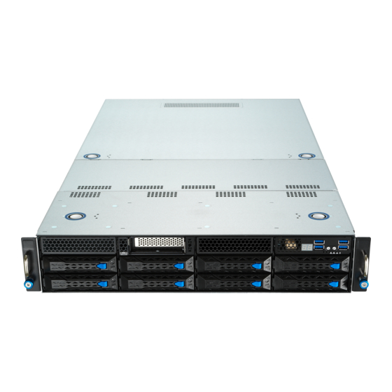
- Page 1 ESC4000A-E10 2U Rackmount Server User Guide...
- Page 2 ASUSTeK COMPUTER INC. (“ASUS”). ASUS provides this manual “as is” without warranty of any kind, either express or implied, including but not limited to the implied warranties or conditions of merchantability or fitness for a particular purpose. In no...
-
Page 3: Table Of Contents
Installing the 2.5-inch SSD/SATA HDD/SAS HDD/NVMe..2-12 Expansion slots ..................2-13 2.5.1 The PCI Express riser card ............2-13 2.5.2 Installing an ASUS PIKE II card ..........2-16 2.5.3 Installing an M.2 expansion card..........2-22 2.5.4 Installing an M.2 (NGFF) card ........... 2-25 2.5.5... - Page 4 Internal connectors ..................4-8 Onboard LEDs ..................4-16 Chapter 5: BIOS Setup Managing and updating your BIOS ............5-2 5.1.1 ASUS CrashFree BIOS 3 utility........... 5-2 5.1.2 ASUS EZ Flash Utility ..............5-3 5.1.3 BUPDATER utility ............... 5-4 BIOS setup program .................. 5-6 5.2.1...
- Page 5 Change Smbios Event Log Settings ......... 5-45 5.12.2 View Smbios Event Log ............5-46 5.13 Server Mgmt menu ................... 5-47 Chapter 6: Driver Installation Running the Support DVD ................. 7-2 Appendix KRPG-U8 block diagram ..................A-2 Notices ........................A-3 ASUS contact information ..................A-6...
-
Page 6: Safety Information
Safety information Electrical Safety • Before installing or removing signal cables, ensure that the power cables for the system unit and all attached devices are unplugged. • To prevent electrical shock hazard, disconnect the power cable from the electrical outlet before relocating the system. -
Page 7: About This Guide
About this guide Audience This user guide is intended for system integrators, and experienced users with at least basic knowledge of configuring a server. Contents This guide contains the following parts: Chapter 1: Product Introduction This chapter describes the general features of the server, including sections on front panel and rear panel specifications. - Page 8 Refer to the following sources for additional information, and for product and software updates. ASUS Control Center (ACC) user guide This manual tells how to set up and use the proprietary ASUS server management utility. ASUS websites The ASUS websites worldwide provide updated information for all ASUS hardware and software products.
-
Page 9: Chapter 1: Product Introduction
Chapter 1: Product Introduction Product Introduction This chapter describes the general features of the chassis kit. It includes sections on front panel and rear panel specifications. -
Page 10: System Package Contents
If any of the above items is damaged or missing, contact your retailer. Serial number label Before requesting support from the ASUS Technical Support team, you must take note of the product’s serial number containing 12 characters such as xxS0xxxxxxxx. See the figure below. -
Page 11: System Specifications
System specifications The ASUS ESC4000A-E10 Series servers features the ASUS KRPG-U8 server board that supports AMD EPYC™ 7002 Series Processor Family. Model Name ESC4000A-E10 Processor / System Bus AMD EPYC™ 7002 Series Processor Family (up to TDP 280W) 8 (8-channel per CPU, 8 DIMM per CPU) - Page 12 ESC4000A-E10 ® ® ® Windows Server 2019, RedHat , SuSE , Ubuntu, Vmware OS Support * Please find the latest OS support from http://www.asus.com/ Out of Band Management Remote On-Board ASMB9-iKVM for KVM-over-IP Hardware Solution Software ASUS Control Center (Classic)
-
Page 13: Front Panel Features
Power cord connector and 4 Full-length Expansion slots Redundant power supply • The rear I/O ports do not appear on the rear panel if motherboard is not present. • *The DM_LAN1 port is for ASUS ASMB9-iKVM controller only. ASUS ESC4000A-E10... -
Page 14: Internal Features
Internal features The barebone server includes the basic components as shown. Redundant power supply and power fan (hidden) ASUS KRPG-U8 server board System fans SATA/SAS/U.2 backplane Hot-swap Storage Device bays (SAS, SATA, and U.2) PCI-E expansion boards (hidden) PCI-E x32 slot with... -
Page 15: Led Information
A hardware monitor event is indicated Function off Location button with Location switch is pressed (Press the location switch again to turn off) No LAN connection Blinking LAN is transmitting or receiving data LAN LEDs LAN connection is present ASUS ESC4000A-E10... -
Page 16: Lan (Rj-45) Leds
1.7.2 LAN (RJ-45) LEDs ACT/LINK LED SPEED LED ACT/LINK LED SPEED LED LAN1/LAN2 LEDs ACT/LINK LED SPEED LED Status Description Status Description No link 10 Mbps connection GREEN Linked ORANGE 100 Mbps connection BLINKING Data activity GREEN 1 Gbps connection Dedicated Management LAN (for ASMB9 and DM_LAN1) ACT/LINK LED SPEED LED... -
Page 17: Hdd Status Leds
Green LED SATA/SAS HDD LED Description GREEN SATA/SAS HDD power ON HDD has failed and should be swapped immediately GREEN/ Blinking RAID rebuilding GREEN/ Blinking Locate GREEN/ HDD not found GREEN Blinking Read/write data from/into the SATA/SAS HDD ASUS ESC4000A-E10... -
Page 18: Q-Code/Port 80 Status Leds
1.7.4 Q-Code/Port 80 status LEDs The Q-Code LED provides a 2-digit display that shows the status of your system. Refer to the Q-Code table of this user guide for more information about the 2-digit codes. Q-Code table Action PHASE POST CODE TYPE DESCRIPTION Progress... - Page 19 BIOS Setup Utility password verify 0xA9 Progress BIOS Setup Utility start 0xAB Progress BIOS Setup Utility input wait 0xAD Progress Ready to boot event 0xAE Progress Legacy boot event 0xAA Progress APIC mode Operating system phase 0xAC Progress PIC mode ASUS ESC4000A-E10 1-11...
- Page 20 1-12 Chapter 1: Product Introduction...
-
Page 21: Chapter 2: Hardware Setup
Chapter 2: Hardware Setup Hardware Setup This chapter lists the hardware setup procedures that you have to perform when installing or removing system components. -
Page 22: Chassis Cover
Chassis cover There are three parts of the chassis cover you may remove. The diagrams in this section are for reference only. The system layout may vary with models, but the installation steps are the same for all models. To remove the rear chassis cover: Release the two (2) thumbscrews on the rear of the chassis. - Page 23 Lift the chassis cover to completely remove it from the chassis. A protection film is pre-attached to the system cover before shipping. Please remove the protection film before turning on the system for proper heat dissipation. ASUS ESC4000A-E10...
-
Page 24: Air Duct
2.1.1 Air duct The diagrams in this section are for reference only. The system layout may vary with models, but the installation steps are the same for all models. To remove the air duct: Remove the three screws as shown. Lift the air duct to remove it from the chassis. -
Page 25: Central Processing Unit (Cpu)
Contact your retailer immediately if the PnP cap is missing, or if you see any damage to the PnP cap/socket contacts/motherboard components. ASUS will shoulder the cost of repair only if the damage is shipment/ transit-related. - Page 26 Loosen each screw one by one in the sequence shown on the socket to open the load plate. Load plate Slightly lift open the rail frame. Rail frame External cap External cap Slide the external cap out of the rail frame.
- Page 27 CPU, then secure each screw one by one in the sequence shown on the socket to completely secure the load plate. The load plate screws are T20 models. A torque value of 14+/-1.0 inch-lbf is recommended. ASUS ESC4000A-E10...
- Page 28 Twist each of the four screws with a screwdriver in the order shown in the illustration just enough to attach the heatsink to the motherboard. When the four screws are attached, tighten them one by one in a the same diagonal sequence to completely secure the heatsink.
-
Page 29: System Memory
You may install 16 GB, 32 GB, 64 GB, 128 GB, 256 GB DDR4 RDIMMs into the DIMM sockets using the memory configurations in this section. • Refer to ASUS Server AVL for the updated list of compatible DIMMs. • Always install DIMMs with the same CAS latency. For optimum compatibility, it is recommended that you obtain memory modules from the same vendor. - Page 30 To install two or more DIMMs, refer to the user guide bundled in the motherboard package. • Refer to www.asus.com for vendor lists of the memory modules. Removing a DIMM from a single clip DIMM socket Press the retaining clip outward to unlock the DIMM.
-
Page 31: Hard Disk Drives
When installed, the SATA/SAS connector on the drive connects to the SATA/SAS interface on the backplane. • The drive tray is correctly placed when its front edge aligns with the bay edge. Repeat steps 1 to 4 to install the other SATA/SAS HDDs. ASUS ESC4000A-E10 2-11... -
Page 32: Installing The 2.5-Inch Ssd/Sata Hdd/Sas Hdd/Nvme
2.4.2 Installing the 2.5-inch SSD/SATA HDD/SAS HDD/NVMe The NVMe drives may be installed in storage device bays 5, 6, 7, and 8 as shown in the illustration below: • The default storage device bays to install NVMe drives are storage device bays 7 and 8. •... -
Page 33: Expansion Slots
To install PCI-E expansion cards to the riser card: Remove the two (2) screws that secure the riser card to the chassis. Firmly hold the riser card then pull it up to detach it from the PCI Express x32 slot on the motherboard. ASUS ESC4000A-E10 2-13... - Page 34 Remove the two (2) screws from the metal brackets on the riser card (A), then remove the metal brackets from the riser card (B). Prepare the expansion cards. Before installing an expansion card, read the documentation that came with it and ensure to make the necessary hardware settings.
- Page 35 The expansion card fits in one orientation only. If it does not fit, try reversing it. Secure the riser card with the two (2) screws that you removed earlier in step 1. PCI-E slot riser card and expansion card assembly ASUS ESC4000A-E10 2-15...
-
Page 36: Installing An Asus Pike Ii Card
2.5.2 Installing an ASUS PIKE II card You may install an ASUS PIKE II card to the internal SAS/HBA/Storage bracket located in the front of the system. Remove the two (2) default slimline SAS cables from the internal SAS/HBA/Storage bracket. - Page 37 Remove the screw from the metal bracket (A), then remove the metal bracket. Prepare the ASUS PIKE II card. Remove the two screws on the ASUS PIKE II Card bracket card (A), then remove the card bracket (B). Secure the ASUS PIKE II card and the metal...
- Page 38 Connect the two (2) slimline SAS cables from the internal SAS/HBA/Storage bracket previously earlier. Install the internal SAS/HBA/Storage bracket and secure it with the screw removed earlier. Remove the three (3) cables on the Cache Vault Power Module clip holder (A), then release the two (2) screws on the Cache Vault Power Module clip holder (B).
- Page 39 Cache Vault Power Module clip holder, then secure the clip with the bundled three (3) screws and three (3) bundled nuts. Align and install the Cache Vault Power Module into the Cache Vault Power Module clip. ASUS ESC4000A-E10 2-19...
- Page 40 Insert the Cache Vault Power Module clip holder into the server system (A), then connect the bundled extension cable to the cable from the Cache Vault Power Module (B) and cable from the Cache Vault Flash Module (C). Reconnect the three (3) cables to the Cache Vault Power Module clip holder, ensure that the cables are not placed on top of the Cache Vault Power Module.
- Page 41 Secure the Cache Vault Power Module clip holder with the two (2) screws that you removed earlier in step 10. ASUS ESC4000A-E10 2-21...
-
Page 42: Installing An M.2 Expansion Card
2.5.3 Installing an M.2 expansion card You may install an M.2 expansion card to the internal SAS/HBA/Storage bracket located in the front of the system. Remove the two (2) default slimline SAS cables from the internal SAS/HBA/Storage bracket. Prepare your M.2 card, then slide it into the expansion card cage located in the front of the system. - Page 43 M.2 card to the front of the system so that the screw holes on the M.2 card are aligned with the screw holes in the expansion card cage. Secure the M.2 card with two (2) screws as shown in the illustration below. ASUS ESC4000A-E10 2-23...
- Page 44 Connect the two (2) slimline SAS cables removed from the internal SAS/HBA/Storage bracket to your M.2 card. 2-24 Chapter 2: Hardware Setup...
-
Page 45: Installing An M.2 (Ngff) Card
Locate the M.2 connector (NGFF1) on the motherboard. Remove the screw on the stand screw. Prepare the M.2 card, then align and insert the M.2 card into the M.2 connector (NGFF1). Secure the M.2 card with the screw you removed in step 2. ASUS ESC4000A-E10 2-25... -
Page 46: Configuring An Expansion Card
2.5.5 Configuring an expansion card After installing the expansion card, configure it by adjusting the software settings. Turn on the system and change the necessary BIOS settings, if any. See Chapter 5 for information on BIOS setup. Assign an IRQ to the card. Refer to the Standard Interrupt assignments table for more information. -
Page 47: Cable Connections
Slim USB connector (from the motherboard to front I/O board) SLIMPCIE2 connector (from motherboard to SATA/SAS/U.2 backplane board) SLIMPCIE1 connector (from motherboard to internal SAS/HBA/Storage bracket) System fan connectors (from motherboard FRNT_FAN6, and FRNT_FAN7 to system fans) ASUS ESC4000A-E10 2-27... -
Page 48: Sata/Sas Backplane Cabling
SATA/SAS backplane cabling connect to SLIMPCIE1 on the motherboard to support 2 NVMe devices connect to mini-SAS HD connectors 1 and 2 on the motherboard. With two mini-SAS HD cables connected, a total number of 8 SAS/SATA HDDs can be supported connects to the system fans * Ensure to connect the corresponding 8-pin plugs to PWR1 and FAN_PWR1 as shown below: PWR1... -
Page 49: Removable/Optional Components
Locate the cable organizer metal cover in between the system fans. Pull the cable organizer metal cover upwards to remove it from the system. Once you have finished organizing the cables, ensure to replace the cable organizer metal cover. ASUS ESC4000A-E10 2-29... -
Page 50: System Fans
2.8.2 System fans To uninstall the system fans: Hold the system fan by the notches (A), then press the latch inwards (B) to release the system fan from the fan cage. Lift the fan then set it aside. Repeat steps 1 to 2 to uninstall the other system fans. -
Page 51: Redundant Power Supply Units
Hold the PSU lever, press the PSU latch (A) then carefully pull the PSU out of the system chassis (B). PSU lever Prepare the replacement PSU. Align and insert the replacement PSU into the empty PSU bay until it clicks in place. Replacement PSU ASUS ESC4000A-E10 2-31... - Page 52 • The system automatically combines the two power supply modules as a single one. The combined output power varies with input voltages. Refer to the table below for details. 1600W Input Voltage Max. Output Power (Watt) per PSU 100V-127Vac, 13A, 50-60Hz 1000W 200V-240Vac, 9.5A, 50-60Hz 1600W...
-
Page 53: U.2 Drives
2.8.4 U.2 drives For the ESC4000A-E10, additional U.2 drives may be installed in storage device bays 5 and 6 as shown in the illustration below: Storage device bay 5 and 6 To install a U.2 drive: Install the U.2 drive to storage device bay 5 or 6. - Page 54 Connect the slimine SAS cables removed in step 2 to the SLIMPCIE5 and SLIMPCIE6 slots located on the backplane. Connect the slimline SAS cables to SLIMPCIE5 and SLIMPCIE6 2-34 Chapter 2: Hardware Setup...
-
Page 55: Installing Accelerators
GPU card. To do this, get a mylar (A) then attach it to the air duct (B) as shown. The mylar is bundled with the system and included in the accessory box. GPU air duct mylar mylar ASUS ESC4000A-E10 2-35... - Page 56 The Nvidia CPU-12V GPU card will not work, or may even cause damage to the system, if the dongle is not used. The ASUS CPU 8-pin power cable may be used to connect to the GPU card and 6-pin power connector.
- Page 57 From inside the air duct, secure the air duct to the accelerator with two screws. Connect the GPU power cable, dongle, or ASUS CPU 8-pin power cable to the connector on the accelerator as shown. For Intel/AMD/Nvidia GPU card installation...
- Page 58 Get the bracket and place it on a flat and stable surface. Remove the screws on the metal covers (A) then remove the metal covers (B). Insert the GPU cables into the opening on the bracket. Align and insert the golden fingers of the accelerator into the card slot on the bracket. Ensure the card is completely seated on the slot.
- Page 59 Attach the other end of the GPU power cable (6-pin power connector) to an available 6-pin power connector in front of the accelerator bracket. Secure the accelerator brackets to the server chassis with two screws. ASUS ESC4000A-E10 2-39...
- Page 60 2-40 Chapter 2: Hardware Setup...
-
Page 61: Chapter 3: Installation Options
Chapter 3: Installation Options Installation Options This chapter describes how to install the optional components and devices into the barebone server. -
Page 62: Friction Rail Kit
Friction Rail Kit The rail kit package includes: Fixing latches Set of screws Latch screws Rail Washers Rail screws Friction rack rails Front end Rack rails Rear end 3.1.1 Attaching the rack rails Installing the tool-less rack rail To install the tool-less rack rails into the rack: Secure the two fixing latches to the two sides of the server using the set of latch screws. - Page 63 Repeat steps 3 to 5 for the other rack rail. Ensure that the installed rack rails (left and right) are aligned, secured, and stable in place. Lift the server chassis and insert into the rack rail. ASUS ESC4000A-E10...
- Page 64 • Ensure that the rack rail cabinet and the rack posts are stable and standing firmly on a level surface. • We strongly recommend that at least two able-bodied persons perform the steps described in this guide. • We recommend the use an appropriate lifting tool or device, if necessary. Chapter 3: Installation Options...
-
Page 65: Chapter 4: Motherboard Infomation
Chapter 4: Motherboard Infomation Motherboard Information This chapter gives information about the motherboard that comes with the server. This chapter includes the motherboard layout, jumper settings, and connector locations. -
Page 66: Krpg-U8 Motherboard Layout
KRPG-U8 Motherboard layout HDDLED1 MESLED1 VGA1 LAN2 LAN1 DM_LAN1 USB3_2 USB3_1 LOCLED1 VGA_SW1 PWR_SW1 BMC_DEBUGUART1 SBPWR1 BMCLED1 ASPEED AST2500 OCP_SIDE1 LAN_SW2 LAN_SW1 IPMI_SW1 MSD1 SPI1 Super COM1 Lithium Cell TPM1 CMOS Power DM_IP_SEL1 BMC_EN1 INTRUSION1 CPU1 SMART_PSU1 ISATA2 SLIMPCIE2 SLIMPCIE1 PWR1 PWR2 1074... - Page 67 10. MicroSD card slot (MSD1) 4-14 11. OCP3.0 Sideband Signal connector (10-pin OCP_SIDE1) 4-15 Onboard LEDs Page Standby Power LED (SBPWR1) 4-16 Baseboard Management Controller LED (BMCLED1) 4-16 Hard disk activity LED (HDDLED1) 4-17 Message LED (MESLED1) 4-17 Location LED (LOCLED1) 4-18 ASUS ESC4000A-E10...
-
Page 68: Jumpers
Jumpers Clear RTC RAM (CLRTC1) This jumper allows you to clear the CMOS memory system setup parameters by erasing the CMOS Real Time Clock (RTC) RAM data. The onboard button cell battery powers the RAM data in CMOS, which include system setup information such as system passwords. - Page 69 1–2 to activate the VGA feature. LAN controller setting (3-pin LAN_SW1, LAN_SW2) These jumpers allow you to enable or disable the onboard Intel I350-AM2 Gigabit LAN ® 1/2 controllers. Set to pins 1-2 to activate the Gigabit LAN feature. ASUS ESC4000A-E10...
- Page 70 Baseboard Management Controller setting (3-pin BMC_EN1) This jumper allows you to enable (default) or disable on-board BMC. Ensure to set this BMC jumper to enabled to avoid system fan control and hardware monitor error. DMLAN setting (3-pin DM_IP_SEL1) This jumper allows you to select the DMLAN setting. Set to pins 2-3 to force the DMLAN IP to static mode (IP=10.10.10.10, submask=255.255.255.0).
- Page 71 This jumper allows you to select which protocol in the GPU sensor to function. Smart Ride Through jumper (3-pin SMART_PSU1) Set to pins 1-2 to enable the Smart Ride Through (SmaRT) feature to allow uninterrupted operation of the system during an AC loss event. ASUS ESC4000A-E10...
-
Page 72: Internal Connectors
Internal connectors Mini-SAS HD connector (ISATA1-2) This motherboard comes with mini Serial Attached SCSI (SAS) HD connectors, the storage technology that supports Serial ATA. Each connector supports up to four devices. Slim PCIe connectors (SLIMPCIE1-2) Connects the PCIe signal to the front riser card or NVMe port on the backplane. Chapter 4: Motherboard Information... - Page 73 When you remove any chassis component, the sensor triggers and sends a high level signal to these leads to record a chassis intrusion event. The default setting is to short the CHASSIS# and the GND pin by a jumper cap to disable the function. ASUS ESC4000A-E10...
- Page 74 DO NOT forget to connect the fan cables to the fan connectors. Insufficient air flow inside the system may damage the motherboard components. • These are not jumpers! DO NOT place jumper caps on the fan connectors! All fans feature the ASUS Smart Fan technology. Chapter 4: Motherboard Information 4-10...
- Page 75 TPM connector (20-1 pin TPM1) This connector supports a Trusted Platform Module (TPM) system, which can securely store keys, digital certificates, passwords, and data. A TPM system also helps enhance network security, protects digital identities, and ensures platform integrity. ASUS ESC4000A-E10 4-11...
- Page 76 M.2 (NGFF) card slot (NGFF1) This slot allows you to install M.2 devices. This connector supports type 2242 / 2260 / 2280 / 22110 devices on PCIe interface. The M.2 (NGFF) device is purchased separately Chapter 4: Motherboard Information 4-12...
- Page 77 The system may become unstable or may not boot up if the power is inadequate. • Ensure that your power supply unit (PSU) can provide at least the minimum power required by your system. ASUS ESC4000A-E10 4-13...
- Page 78 MicroSD card slot (MSD1) The microSD card slot allows you to install a microSD memory card v2.00 (SDHC) / v3.00 (SDXC) to log BMC events. Disconnect all power (including redundant PSUs) from the existing system before you add or remove a memory card, then reboot the system to access the memory card. Some memory cards may not be compatible with your motherboard.
- Page 79 OCP3.0 Sideband Signal connector (12-pin OCP_SIDE1) This connector is for OCP3.0 sideband signal and allows you to connect an external OCP3.0 card to support additional features such as power brake and scan chain. ASUS ESC4000A-E10 4-15...
-
Page 80: Onboard Leds
Onboard LEDs Standby Power LED (SBPWR1) The motherboard comes with a standby power LED. The green LED lights up to indicate that the system is ON, in sleep mode, or in soft-off mode. This is a reminder that you should shut down the system and unplug the power cable before removing or plugging in any motherboard component. - Page 81 The read or write activities of any device connected to the onboard SATA, or SATA/SAS add-on card causes the rear panel LED to light up. Message LED (MESLED1) This onboard LED lights up to red when there is temperature warning or a BMC event log is generated. ASUS ESC4000A-E10 4-17...
- Page 82 Location LED (LOCLED1) This onboard LED lights up when the Location button on the server is pressed or when triggered by a system management software. The Location LED helps visually locate and quickly identify the server in error on a server rack. Chapter 4: Motherboard Information 4-18...
-
Page 83: Chapter 5: Bios Setup
Chapter 5: BIOS Setup BIOS Setup This chapter tells how to change system settings through the BIOS Setup menus and describes the BIOS parameters. -
Page 84: Managing And Updating Your Bios
5.1.1 ASUS CrashFree BIOS 3 utility The ASUS CrashFree BIOS 3 is an auto recovery tool that allows you to restore the BIOS file when it fails or gets corrupted during the updating process. You can update a corrupted BIOS file using a USB flash drive that contains the updated BIOS file. -
Page 85: Asus Ez Flash Utility
5.1.2 ASUS EZ Flash Utility The ASUS EZ Flash Utility feature allows you to update the BIOS without having to use a DOS-based utility. Before you start using this utility, download the latest BIOS from the ASUS website at www.asus.com. -
Page 86: Bupdater Utility
Updating the BIOS file To update the BIOS file using the BUPDATER utility: Visit the ASUS website at www.asus.com and download the latest BIOS file for the motherboard. Save the BIOS file to a bootable USB flash disk drive. Copy the BUPDATER utility (BUPDATER.exe) from the ASUS support website at www. - Page 87 The utility verifies the file, then starts updating the BIOS file. ASUS Tek. EzFlash Utility Current Platform New Platform Platform : KRPG-U8 Platform : KRPG-U8 Version : 0301 Version : 0301 Build date: 05/22/2020 Build date: 05/31/2020 Start Programming Flash.
-
Page 88: Bios Setup Program
The BIOS setup screens shown in this section are for reference purposes only, and may not exactly match what you see on your screen. • Visit the ASUS website (www.asus.com) to download the latest BIOS file for this motherboard. Chapter 5: BIOS Setup... -
Page 89: Bios Menu Screen
For changing the event log settings Server Mgmt For changing the Server Mgmt settings To select an item on the menu bar, press the right or left arrow key on the keyboard until the desired item is highlighted. ASUS ESC4000A-E10... -
Page 90: Menu Items
5.2.3 Menu items The highlighted item on the menu bar displays the specific items for that menu. For example, selecting Main shows the Main menu items. The other items (such as Advanced) on the menu bar have their respective menu items. 5.2.4 Submenu items A solid triangle before each item on any menu screen means that the item has a submenu. -
Page 91: Main Menu
5.3.1 System Date [Day xx/xx/xxxx] Allows you to set the system date. 5.3.2 System Time [xx:xx:xx] Allows you to set the system time. ASUS ESC4000A-E10... -
Page 92: Performance Tuning Menu
Performance Tuning menu The Performance Tuning menu items allow you to change performance related settings for different scenarios. Optimized Performance Setting [Default] Allows you to select performance settings for different scenarios. [Default] Default settings. [By Benchmark] Optimize for different kinds of benchmarks. Select this option, then select a benchmark type from the >>... - Page 93 Operate with an ambient temperature of 25°C or lower for optimized performance. Please note that overclocking might cause component damage or system crashes, which may reduce the lifespan of the system and the CPU. Use this tool at your own risk. ASUS ESC4000A-E10 5-11...
-
Page 94: Advanced Menu
Advanced menu The Advanced menu items allow you to change the settings for the CPU and other system devices. Take caution when changing the settings of the Advanced menu items. Incorrect field values can cause the system to malfunction. 5.5.1 Trusted Computing Configuration Security Device Support [Enabled]... -
Page 95: Psp Firmware Versions
Enables the PCIE devices to generate a wake event. Power On By RTC [Disabled] [Disabled] Disables RTC to generate a wake event. [Enabled] When set to [Enabled], the items RTC Alarm Date (Days) and Hour/Minute/Second will become user-configurable with set values. ASUS ESC4000A-E10 5-13... -
Page 96: Onboard Lan Configuration
5.5.4 Onboard LAN Configuration Onboard I350 LAN Configuration Intel I350 LAN1 LAN Enable [Jumperstate] Allows you to enable or disable the Intel LAN. Configuration options: [Disabled] [Jumperstate] The following item appears only when LAN Enable is set to [Jumperstate]. ROM Type [PXE] Allows you to select the Intel LAN ROM type. -
Page 97: Serial Port Console Redirection
Bits per second [115200] Selects serial port transmission speed. The speed must be matched on the other side. Long or noisy lines may require lower speeds. Configuration options: [9600] [19200] [38400] [57600] [115200] Data Bits [8] Configuration options: [7] [8] ASUS ESC4000A-E10 5-15... - Page 98 Parity [None] A parity bit can be sent with the data bits to detect some transmission errors. [Mark] and [Space] parity do not allow for error detection. [None] None [Even] parity bit is 0 if the num of 1’s in the data bits is even [Odd] parity bit is 0 if num of 1’s in the data bits is odd [Mark]...
-
Page 99: Cpu Configuration
Microsoft Windows Emergency Management Services (EMS) allow for remote management of a Windows Server OS through a serial port. Configuration options: [None] [Hardware RTS/CTS] [Software Xon/Xoff] 5.5.6 CPU Configuration SVM Mode [Enable] This item allows you enable or disable CPU Virtualization. Configuration options: [Disabled] [Enable] ASUS ESC4000A-E10 5-17... -
Page 100: Pci Subsystem Settings
SMEE [Enable] This item allows you to enable or disable control secure memory encryption. Configuration options: [Disabled] [Enable] Node 0 Information This item allows you to view memory information related to Node 0. Node 1 Information This item allows you to view memory information related to Node 1. 5.5.7 PCI Subsystem Settings Allows you to configure PCI, PCI-X, and PCI Express Settings. -
Page 101: Usb Configuration
Allows you to enable or disable workaround for OSes without XHCI hand-off support. The XHCI ownership change should be claimed by XHCI driver. Configuration options: [Enabled] [Disabled] USB Mass Storage Driver Support [Enabled] Allows you to enable or disable the USB Mass Storage driver support. Configuration options: [Disabled] [Enabled] ASUS ESC4000A-E10 5-19... -
Page 102: Network Stack Configuration
Port 60/64 Emulation [Enabled] Allows you to enable or disable I/O port 60h/64h emulation support. This should be enabled for the complete keyboard legacy support for non-USB aware OSes. onfiguration options: [Disabled] [Enabled] USB hardware delays and time-outs USB transfer time-out [20 sec] Allows you to select time-out value for Control, Bulk, and Interrupt transfers. -
Page 103: Csm Configuration
This option allows you to enable or disable CSM Support. Configuration options: [Disabled] [Enabled] The following items appear only when CSM Support is set to [Enabled]. GateA20 Active [Upon Request] This allows you to set the GA20 option. Configuration options: [Upon Request] [Always] ASUS ESC4000A-E10 5-21... -
Page 104: Nvme Configuration
Option ROM Messages [Force BIOS] This allows you to set the display mode for option ROM. Configuration options: [Force BIOS] [Keep Current] INT19 Trap Response [Immediate] This allows you to select the BIOS reaction on INT19 trapping by Option ROM. [Immediate] Execute the trap right away. -
Page 105: Amd Mem Configuration Status
5.5.13 AMD Mem Configuration Status The items in this menu display the memory configuration (initialized by ABL) status. 5.5.14 iSCSI Configuration Allows you to configure the iSCSi parameters. ASUS ESC4000A-E10 5-23... -
Page 106: Chipset Menu
Chipset menu The Chipset menu items allow you to change the Chipset settings. PCIe Link Training Type [1 Step] This item allows you to select PCIe Link Training in 1 or 2 steps. Configuration options: [1 Step] [2 Step] PCIe Compliance Mode [Off] This item allows you to turn the PCIe Compliance Mode on or off. -
Page 107: Security Menu
From the Create New Password box, key in a new password, then press <Enter>. Confirm the password when prompted. To clear the administrator password, follow the same steps as in changing an administrator password, but press <Enter> when prompted to create/confirm the password. ASUS ESC4000A-E10 5-25... - Page 108 User Password To set a user password: Select the User Password item and press <Enter>. From the Create New Password box, key in a password, then press <Enter>. Confirm the password when prompted. To change a user password: Select the User Password item and press <Enter>. From the Enter Current Password box, key in the current password, then press <Enter>.
- Page 109 Configuration options: [Set New] [Append] Device Guard Ready Remove ‘UEFI CA’ from DB Remove Microsoft UEFI CA from Secure Boot DB. Restore DB defaults Restore DB variable to factory defaults. Platform Key (PK) Configuration options: [Details] [Export] [Update] [Delete] ASUS ESC4000A-E10 5-27...
-
Page 110: Boot Menu
• To select the boot device during system startup, press <F8> when ASUS Logo appears. • To access Windows OS in Safe Mode, please press <F8> after POST. -
Page 111: Tool Menu
IPMI HWM Allows you to run the IPMI hardware monitor. Start ASUS EzFlash Allows you to run ASUS EZ Flash BIOS ROM Utility when you press <Enter>. Refer to the ASUS EZ Flash Utility section for details. ASUS ESC4000A-E10 5-29... -
Page 112: Save & Exit Menu
5.10 Save & Exit menu The Save & Exit menu items allow you to save or discard your changes to the BIOS items. Pressing <Esc> does not immediately exit this menu. Select one of the options from this menu or <F10> from the legend bar to exit. Discard Changes and Exit Exit System setup without saving any changes. -
Page 113: Amd Cbs Menu
Custom Core Pstates This item allows you to enable custom P-states and throttling. Damage caused by use of your AMD processor outside of specification or in excess of factory settings are not covered by your system manufacturers warranty. ASUS ESC4000A-E10 5-31... - Page 114 CCD/Core/Thread Enhancement This item allows you to set CCD/core/threads. S3 is not supported on systems where cores/threads have been removed/disabled. Prefetcher settings L1 Stream HW Prefetcher [Auto] This item allows you to enable or disable L1 Stream HW Prefetcher. Configuration options: [Disable] [Enable] [Auto] L2 Stream HW Prefetcher [Auto] This item allows you to enable or disable L2 Stream HW Prefetcher.
-
Page 115: Df Common Options
Poison scrubber control [Auto] Configuration options: [Disabled] [Enabled] [Auto] Redirect scrubber control [Auto] Configuration options: [Disabled] [Enabled] [Auto] Redirect scrubber limit [Auto] Configuration options: [2] [4] [8] [Infinite] [Auto] Periodic Directory Rinse [Auto] Configuration options: [Disabled] [Enabled] [Auto] ASUS ESC4000A-E10 5-33... - Page 116 Memory Addressing NUMA nodes per socket [Auto] Specifies the number of desired NUMA nodes per socket. Zero will attempt to interleave the two sockets together. Configuration options: [NPS0] [NPS1] [NPS2] [NPS4] [Auto] Memory interleaving [Auto] This items allows for disabling memory interleaving. Note that NUMA nodes per socket will be honored regardless of this setting.
-
Page 117: Umc Common Option
Configuration options: [Auto] [Manual] The following items appear only when CAD Bus Timing User Controls is set to [Manual]. AddrCmdSetup [0] This item allows you to setup time on CAD bus signals. Configuration options: [0] - [39] ASUS ESC4000A-E10 5-35... - Page 118 CsOdtSetup [0] This item allows you to setup time on CAD bus signals. Configuration options: [0] - [39] CkeSetup [0] This item allows you to setup time on CAD bus signals. Configuration options: [0] - [39] CAD Bus Drive Strength User Controls [Auto] This item allows you to set the CAD bus signals to Auto or Manual.
- Page 119 Configuration options: [Disabled] [Enabled] [Auto] DRAM Memory Mapping Chipselect Interleaving [Auto] This item allows you to set interleave memory blocks across the DRAM chip selects for node 0. Configuration options: [Disabled] [Auto] BankGroupSwap [Auto] Configuration options: [Enabled] [Disabled] [Auto] ASUS ESC4000A-E10 5-37...
- Page 120 BankGroupSwapAlt [Auto] Configuration options: [Enabled] [Disabled] [Auto] Address Hash Bank [Auto] This item allows you to enable or disable bank address hashing. Configuration options: [Enabled] [Disabled] [Auto] Address Hash CS [Auto] This item allows you to enable or disable CS address hashing. Configuration options: [Enabled] [Disabled] [Auto] Address Hash Rm [Auto] This item allows you to enable or disable RM address hashing.
- Page 121 This option determines which results are expected to be captured for Data Eye. Supported options are 1D Voltage Sweep, 1D Timing Sweep, 2D Full Data Eye and Worst Case Margin only. Configuration options: [1D Voltage Sweep] [1D Timing Sweep] [2D Full Data Eye] [Worst Case Margin Only] ASUS ESC4000A-E10 5-39...
-
Page 122: Nbio Common Options
Worst Case Margin Granularity [Per Chip Select] Configuration options: [Per Chip Select] [Per Nibble] Read Voltage Sweep Step Size [2] This option determines the step size for Read Data Eye voltage sweep. Configuration options: [1] [2] [4] Read Timing Sweep Step Size [1] This option supports step size for Read Data Eye. - Page 123 Configuration options: [0] [1] [Auto] DF Cstates [Auto] Configuration options: [Disabled] [Enabled] [Auto] CPPC [Auto] Configuration options: [Disabled] [Enabled] [Auto] HSMP Support [Auto] This item allows you to enable or disable HSMP support. Configuration options: [Disabled] [Enabled] [Auto] ASUS ESC4000A-E10 5-41...
- Page 124 Diagnostic Mode [Auto] This item allows you to enable or disable Diag mode. Configuration options: [Disabled] [Enabled] [Auto] DLWM Support [Auto] This item allows you to enable or disable DLWM support. Configuration options: [Disabled] [Enabled] [Auto] BoostFmaxEn [Auto] [Auto] Use the default Fmax. [Manual] User can set the boost Fmax.
- Page 125 Configuration options: [Disabled] [Enabled] [Auto] Sync Flood on PCIe Fatal Error [Auto] Configuration options: [Auto] [True] [False] Enable AER Cap [Auto] This item allows you to enable or disable Advanced Error Reporting Capability. Configuration options: [Enable] [Disabled] [Auto] ASUS ESC4000A-E10 5-43...
-
Page 126: Ntb Common Options
Enable Rcv Err and Bad TLP Mask [Auto] This item allows you to enable masking of receiver error and bad TLP at Gen4 x2. Configuration options: [Disabled] [Enabled] [Auto] Early Link Speed [Auto] This item allows you to set Early Link Speed. Configuration options: [Auto] [Gen1] [Gen2] Hot Plug Handling mode [Auto] This item allows you to control the Hot Plug Handling mode. -
Page 127: Event Logs Menu
Press <Enter> to change the Smbios Event Log configuration. All values changed here do not take effect until computer is restarted. Enabling/Disabling Options Smbios Event Log [Enabled] Change this to enable or disable all features of Smbios Event Logging during boot. Configuration options: [Disabled] [Enabled] ASUS ESC4000A-E10 5-45... -
Page 128: View Smbios Event Log
The following item appears only when Smbios Event Log is set to [Enabled]. Erasing Settings Erase Event Log [No] Choose options for erasing Smbios Event Log. Erasing is done prior to any logging activation during reset. Configuration options: [No] [Yes, Next reset] [Yes, Every reset] Smbios Event Log Standard Settings Log System Boot Event [Disabled] This option allows you to enable or disable logging System boot event. -
Page 129: Server Mgmt Menu
Configuration options: [Do Nothing] [Reset] [Power Down] [Power Cycle] OS Watchdog Timer [Disabled] This item allows you to start a BIOS timer which can only be shut off by Intel Management Software after the OS loads. Configuration options: [Disabled] [Enabled] ASUS ESC4000A-E10 5-47... - Page 130 The following items appear only when OS Watchdog Timer is set to [Enabled]. OS Wtd Timer Timeout [10 minutes] Allows you to configure the length fo the OS Boot Watchdog Timer. Configuration options: [5 minutes] [10 minutes] [15 minutes] [20 minutes] OS Wtd Timer Policy [Reset] This item allows you to configure the how the system should respond if the OS Boot Watch Timer expires.
- Page 131 This item allows you to view the system event log records. BMC User Settings The sub-items in this configuration allow you to add, delete, or change BMC user settings. BMC Warm Reset Press <Enter> to perform a BMC Warm Reset. ASUS ESC4000A-E10 5-49...
- Page 132 Chapter 5: BIOS Setup 5-50...
-
Page 133: Chapter 6: Driver Installation
Chapter 6: Driver Installation Driver Installation This chapter provides instructions for installing the necessary drivers for different system components. -
Page 134: Running The Support Dvd
Manual - Provides the link to the user guide(s). You need an internet browser installed in your OS to view the User Guide. Contact - Displays the ASUS contact information, e-mail addresses, and useful links if you need more information or technical support for your motherboard. -
Page 135: Appendix
Appendix Appendix This appendix includes additional information that you may refer to when configuring the motherboard. ASUS ESC4000A-E10... -
Page 136: Krpg-U8 Block Diagram
KRPG-U8 block diagram Appendix... -
Page 137: Notices
économique Canada applicables aux appareils radio exempts de licence. L’exploitation est autorisée aux deux conditions suivantes : (1) l’appareil ne doit pas produire de brouillage, et (2) l’utilisateur de l’appareil doit accepter tout brouillage radioélectrique subi, même si le brouillage est susceptible d’en compromettre le fonctionnement. CAN ICES-3(A)/NMB-3(A) ASUS ESC4000A-E10... - Page 138 ASUS follows the green design concept to design and manufacture our products, and makes sure that each stage of the product life cycle of ASUS product is in line with global environmental regulations. In addition, ASUS disclose the relevant information based on regulation requirements.
- Page 139 ASUS products sold in Vietnam, on or after September 23, 2011,meet the requirements of the Vietnam Circular 30/2011/TT-BCT. Các sản phẩm ASUS bán tại Việt Nam, vào ngày 23 tháng 9 năm2011 trở về sau, đều phải đáp ứng các yêu cầu của Thông tư 30/2011/TT-BCT của Việt Nam.
-
Page 140: Asus Contact Information
ASUS contact information ASUSTeK COMPUTER INC. Address 1F., No. 15, Lide Rd., Beitou Dist., Taipei City 112, Taiwan Telephone +886-2-2894-3447 +886-2-2890-7798 Web site https://www.asus.com Technical Support Telephone +86-21-38429911 Online Support https://www.asus.com/support/Product/ContactUs/Services/ questionform/?lang=en ASUSTeK COMPUTER INC. (Taiwan) Address 1F., No. 15, Lide Rd., Beitou Dist., Taipei City 112, Taiwan... - Page 141 Web site https://www.asus.com/us/ Technical Support Support fax +1-812-284-0883 General support +1-812-282-2787 Online support https://www.asus.com/support/Product/ContactUs/Services/ questionform/?lang=en-us ASUS COMPUTER GmbH (Germany and Austria) Address Harkort Str. 21-23, 40880 Ratingen, Germany Web site https://www.asus.com/de/ Technical Support Telephone (DE) +49-2102-5789557 Telephone (AT) +43-1360-2775461 Online support https://www.asus.com/support/Product/ContactUs/Services/...
- Page 142 Web site https://www.asus.com/nl/ Technical Support Telephone +31-(0)591-5-70292 +31-(0)591-666853 E-mail advance.rma.eu@asus.com Online Support https://www.asus.com/support/Product/ContactUs/Services/ questionform/?lang=nl-nl ASUS Polska Sp. z o.o. (Poland) Address Ul. Postępu 6, 02-676 Warszawa, Poland Web site https://www.asus.com/pl/ Technical Support Telephone +48-225718033 Online Support https://www.asus.com/support/Product/ContactUs/Services/ questionform/?lang=pl-pl ASK-Service (Russia and CIS) г.Москва, ул.