Table of Contents
Advertisement
Quick Links
Advertisement
Table of Contents

Related Manuals for Asus ESC4000 G4


Summary of Contents for Asus ESC4000 G4
- Page 1 ESC4000 G4 Series 2U Rackmount Server User Guide...
- Page 2 ASUSTeK COMPUTER INC. (“ASUS”). ASUS provides this manual “as is” without warranty of any kind, either express or implied, including but not limited to the implied warranties or conditions of merchantability or fitness for a particular purpose. In no...
- Page 3 The PCI Express riser card ............2-17 2.5.2 Installing an ASUS PIKE II card ..........2-20 2.5.3 Installing an ASUS HFI-OMNI 100G LAN card ......2-24 2.5.4 Configuring an expansion card ..........2-27 Cable connections ................... 2-28 SATA/SAS backplane cabling ..............2-29...
- Page 4 Internal connectors .................. 4-10 Onboard LEDs ..................4-20 Chapter 5: BIOS Setup Managing and updating your BIOS ............5-2 5.1.1 ASUS CrashFree BIOS 3 utility........... 5-2 5.1.2 ASUS EZ Flash Utility ..............5-3 5.1.3 BUPDATER utility ............... 5-4 BIOS setup program .................. 5-6 5.2.1...
- Page 5 Contents Advanced menu ..................5-10 5.4.1 Trusted Computing..............5-10 5.4.2 ACPI Settings ................5-11 5.4.3 SMART Settings................ 5-11 5.4.4 Super IO Configuration ............. 5-12 5.4.5 Serial Port Console Redirection ..........5-12 5.4.6 Onboard LAN Configuration ............. 5-15 5.4.7 APM ..................5-16 5.4.8 PCI Subsystem Settings ............
- Page 6 ..........7-8 ® Installing the Intel I210 Gigabit Adapters driver ........7-10 VGA driver installation ................7-13 ® Intel Rapid Storage Technology enterprise 5.0 installation ....7-15 Appendix Z11PG-D16 block diagram ..................A-2 ASUS contact information ..................A-3...
-
Page 7: Federal Communications Commission Statement
Notices Federal Communications Commission Statement This device complies with Part 15 of the FCC Rules. Operation is subject to the following two conditions: • This device may not cause harmful interference, and • This device must accept any interference received including interference that may cause undesired operation. - Page 8 ASUS REACH website at http://csr.asus.com/english/REACH.htm. ASUS Recycling/Takeback Services ASUS recycling and takeback programs come from our commitment to the highest standards for protecting our environment. We believe in providing solutions for you to be able to responsibly recycle our products, batteries, other components as well as the packaging materials.
-
Page 9: Safety Information
Safety information Electrical Safety • Before installing or removing signal cables, ensure that the power cables for the system unit and all attached devices are unplugged. • To prevent electrical shock hazard, disconnect the power cable from the electrical outlet before relocating the system. -
Page 10: About This Guide
About this guide Audience This user guide is intended for system integrators, and experienced users with at least basic knowledge of configuring a server. Contents This guide contains the following parts: Chapter 1: Product Introduction This chapter describes the general features of the server, including sections on front panel and rear panel specifications. - Page 11 Refer to the following sources for additional information, and for product and software updates. ASUS Control Center (ACC) user guide This manual tells how to set up and use the proprietary ASUS server management utility. ASUS websites The ASUS websites worldwide provide updated information for all ASUS hardware and...
-
Page 13: Product Introduction
Chapter 1: Product Introduction Product Introduction This chapter describes the general features of the chassis kit. It includes sections on front panel and rear panel specifications. -
Page 14: System Package Contents
2 x AC Power Cables Accessory box 8 x 4-pin VGA Power cables 4 x ASUS CPU 8-pin Power cables 8 x GPU air ducts (4 for Intel Xeon Phi; 4 for Nvidia/AMD) 4 x Mylar for GPU air ducts for AMD GPU... -
Page 15: Serial Number Label
With the correct serial number of the product, ASUS Technical Support team members can then offer a quicker and satisfying solution to your problems. ESC4000 G4 xxS0xxxxxxxx ESC4000 G4X xxS0xxxxxxxx The serial number on ESC4000 G4, and ESC4000 G4X are printed on the Asset tag. ASUS ESC4000 G4 Series... -
Page 16: System Specifications
1.3 System specifications The ASUS ESC4000 G4 Series servers features the ASUS Z11PG-D16 Series server board ® ® that supports Intel LGA 3647 Xeon processor from the Skylake F and Skylake-SP product family. Model Name ESC4000 G4 ESC4000 G4X 1 x Socket P0 (LGA 3647) - Page 17 RAID 0, 1, 10 & 5) software RAID 0 & 1) Optional kits: ASUS PIKE II 3008 8-port SAS HBA card SAS ASUS PIKE II 3108 8-port SAS HW RAID card Controller 12G SAS Support * Support with the PCI-E riser card. 8 x 3.5" Hot-swap 2 x 2.5"...
- Page 18 Server 2012 R2 ® RedHat Enterprise Linux ® SuSE Linux Enterprise Server CentOS OS Support Ubuntu VMware Citrix XenServer * Please find the latest OS support from http://www.asus.com/ Out of Band Remote On-Board ASMB9-iKVM for KVM-over-IP Management Hardware Solution Software 800mm * 440mm * 88mm (2U) Dimension (HH x WW x DD) 31.50" x 17.22" x 3.46"...
-
Page 19: Front Panel Features
LED indicators, and USB ports are located and easily accessible on the front panel. Refer to the 1.7.1 Front panel LEDs section for the LED descriptions. ESC4000 G4 Q-code/Port 80 LED Location button Internal SAS/HBA/Storage bracket Power button USB 3.0 ports Steel handle Steel handle Front panel LED USB 2.0 ports Hot-swap 3.5-inch HDD Bays Asset tag ESC4000 G4X Steel handle Steel handle Power Location button button USB 2.0 ports USB 3.0 ports Q-code/Port 80 LED Front panel LED ASUS ESC4000 G4 Series... -
Page 20: Rear Panel Features
ESC4000 G4 / G4X Half-length / Low-profile expansion slot LAN port 2 LAN port 1 4 Full-length Expansion slots 4 Full-length Expansion slots Power cord connector and Redundant power supply • The rear I/O ports do not appear on the rear panel if motherboard is not present. • *The DM_LAN1 port is for ASUS ASMB9-iKVM controller only. Chapter 1: Product Introduction... -
Page 21: Internal Features
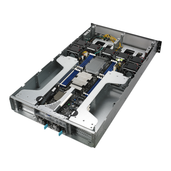
A protection film is pre-attached to the front cover before shipping. Please remove the protection film before turning on the system for proper heat dissipation. WARNING HAZARDOUS MOVING PARTS KEEP FINGERS AND OTHER BODY PARTS AWAY ASUS ESC4000 G4 Series... - Page 22 ESC4000 G4X Redundant power supply and power fan (hidden) ASUS Z11PG-D16 server board System fans HDD tray (SAS, SATA, and U.2) PCI-E expansion boards (hidden) PCI-E x24 slot with butterfly riser card FAN7 FAN6 FAN5 FAN4 FAN3 FAN2 FAN1 The barebone server does not include a floppy disk drive or an optical dirve. Connect a USB floppy disk drive to any of the USB ports on the front or rear panel if you need to use a floppy disk.
-
Page 23: Led Information
1.7 LED information 1.7.1 Front panel LEDs ESC4000 G4 Location button with LED Power button with LED LAN2 LED HDD Access LED LAN1 LED Message LED ESC4000 G4X Location button with LED Power button with LED LAN2 LED HDD Access LED LAN1 LED Message LED ASUS ESC4000 G4 Series 1-11... - Page 24 Display Icon Description status Power button with LED System power on No activity HDD access LED Blinking Data activity System is normal; no incoming event Message LED A hardware monitor event is indicated Function off Location button with Location switch is pressed (Press the location switch again to turn off) No LAN connection Blinking LAN is transmitting or receiving data...
-
Page 25: Lan (Rj-45) Leds
100 Mbps connection BLINKING Data activity GREEN 1 Gbps connection Dedicated Management LAN (for ASMB9 and DM_LAN1) ACT/LINK LED SPEED LED Status Description Status Description No link 10 Mbps connection ORANGE Linked ORANGE 100 Mbps connection BLINKING Data activity GREEN 1 Gbps connection ASUS ESC4000 G4 Series 1-13... -
Page 26: Hdd Status Leds
1.7.3 HDD status LEDs ESC4000 G4 Red LED Green LED SATA/SAS HDD LED Description GREEN SATA/SAS HDD power ON HDD has failed and should be swapped immediately GREEN/ Blinking RAID rebuilding GREEN/ Blinking Locate GREEN/ HDD not found GREEN Blinking Read/write data from/into the SATA/SAS HDD 1-14 Chapter 1: Product Introduction... -
Page 27: Q-Code/Port 80 Status Leds
CPU PM CSR programming 0xD2 Progress CPU PM MSR programming 0xD3 Progress CPU PM PSTATE transition 0xD4 Progress CPU PM driver exit 0xD5 Progress CPU PM On ready to boot event (continued on the next page) ASUS ESC4000 G4 Series 1-15... - Page 28 Q-Code table Action PHASE POST CODE TYPE DESCRIPTION 0x90 Progress BDS started 0x91 Progress Connect device event 0x92 Progress PCI Bus Enumeration 0x93 Progress PCI Bus Enumeration 0x94 Progress PCI Bus Enumeration 0x95 Progress PCI Bus Enumeration 0x96 Progress PCI Bus Enumeration 0x97 Progress Console outout connect event...
-
Page 29: Hardware Setup
Chapter 2: Hardware Setup Hardware Setup This chapter lists the hardware setup procedures that you have to perform when installing or removing system components. -
Page 30: Chassis Cover
Chassis cover There are three parts of the chassis cover you may remove. The diagrams in this section are for reference only. The system layout may vary with models, but the installation steps are the same for all models. To remove the rear chassis cover: Release the two (2) thumbscrews on the rear of the chassis. - Page 31 Lift the chassis cover to completely remove it from the chassis. A protection film is pre-attached to the system cover before shipping. Please remove the protection film before turning on the system for proper heat dissipation. ASUS ESC4000 G4 Series...
-
Page 32: Air Duct
2.1.1 Air duct The diagrams in this section are for reference only. The system layout may vary with models, but the installation steps are the same for all models. To remove the air duct: Remove the three screws as shown. Lift the air duct to remove it from the chassis. - Page 33 Align and replace the CPU air duct to the chassis Align and replace the air duct to the chassis ensuring that the screw holes on the air duct match the screw holes on chassis. Secure the air duct to the chassis with three screws. ASUS ESC4000 G4 Series...
-
Page 34: Central Processing Unit (Cpu)
Contact your retailer immediately if the PnP cap is missing, or if you see any damage to the PnP cap/socket contacts/motherboard components. ASUS will shoulder the cost of repair only if the damage is shipment/ transit-related. - Page 35 CPU Carrier into the socket to prevent damaging the CPU pins on the socket. The heatsink for ESC4000 G4 Series differs between CPU1 and CPU2, please refer to the illustration below for more information on the heatsink and the corresponding CPU socket.
- Page 36 Twist each of the four screws with a screwdriver just enough to attach the heatsink to the motherboard. When the four screws are attached, tighten them one by one in a diagonal sequence to completely secure the heatsink. The heatsink screws are T30 models. A torque value of 12 inch-lbf is recommended. Reinstall the air duct.
-
Page 37: System Memory
128GB LRDIMMs (3DS) into the DIMM sockets using the memory configurations in this section. • Refer to ASUS Server AVL for the updated list of compatible DIMMs. • When installing only one DIMM in a single CPU configuration, install the DIMM on either A1 or B1. - Page 38 1 CPU Configuration 1 DIMM • 2 DIMMs • • 6 DIMMs • • • • • • • • • • • • • • 8 DIMMs 2 CPU Configuration 1 DIMM • • • 2 DIMMs • • 4 DIMMs 12 DIMMs •...
-
Page 39: Installing A Dimm On A Single Clip Dimm Socket
To install two or more DIMMs, refer to the user guide bundled in the motherboard package. • Refer to www.asus.com for vendor lists of the memory modules. Removing a DIMM from a single clip DIMM socket Press the retaining clip outward to unlock the DIMM. -
Page 40: Hard Disk Drives
Hard disk drives The ESC4000 G4 series supports 3.5-inch and 2.5-inch SATA/SAS hard disk drives, or U.2 drives. For the ESC4000 G4 system, the hard disk drive installed on the drive tray connects to the motherboard SATA/SAS ports via the SATA/SAS backplane. - Page 41 Prepare the SATA/SAS HDD and the bundled set of screws. Place the SATA/SAS HDD into the HDD cage. Secure the SATA/SAS HDD with four (4) screws. Connect the SATA and power cable to your SATA/SAS HDD. ASUS ESC4000 G4 Series 2-13...
- Page 42 Align and replace the SATA/SAS HDD and HDD cage assembly into the chassis. Secure the SATA/SAS HDD and HDD cage assembly to the chassis using the four (4) screws removed earlier. Repeat steps 1 to 8 to install the other SATA/SAS HDD. 2-14 Chapter 2: Hardware Setup...
-
Page 43: Installing The 2.5-Inch Ssd/Satad/Sas Hdd/Nvme
2.4.2 Installing the 2.5-inch SSD/SATAD/SAS HDD/NVME ESC4000 G4 For the ESC4000 G4, the NVME drives may be installed in HDD bay 7 and 8 as shown in the illustration below: HDD bay 7 and 8 Remove the drive tray. Refer to section ESC4000 G4 under 2.4.1 Installing the 3.5-inch SATA HDD/SAS HDD for the steps on removing the drive tray. - Page 44 (optional) Connect the NVME cable to your NVME device. The NVME cable is optional, for more information about the optional NVME cable, please visit www.asus.com/ support. (optional) Replace the HDD cage. Refer to section ESC4000 G4X under 2.4.1 Installing the 3.5-inch SATA HDD/SAS HDD for the steps on replacing the HDD cage.
-
Page 45: Expansion Slots
The onboard PCI Express slot on the motherboard comes pre-installed with a riser card that supports one x16 slot (x8 Gen3 link) for installing PCI-E x16 low profile cards and one x8 slot (x8 Gen3 link) for installing ASUS PCI-E x8 low profile cards. To install PCI-E expansion cards to the riser card: Remove the two (2) screws that secure the riser card to the chassis. - Page 46 Remove the two (2) screws from the metal brackets on the riser card (A), then remove the metal brackets from the riser card (B). Prepare the expansion cards. Before installing an expansion card, read the documentation that came with it and ensure to make the necessary hardware settings.
- Page 47 The expansion card fits in one orientation only. If it does not fit, try reversing it. Secure the riser card with the two (2) screws that you removed earlier in step 1. PCI-E slot riser card and expansion card assembly ASUS ESC4000 G4 Series 2-19...
-
Page 48: Installing An Asus Pike Ii Card
To install an ASUS PIKE II card to the front of the system (ESC4000 G4 only): Remove the default cable from the motherboard and the backplane. - Page 49 Remove the screw from the metal bracket (A), then remove the metal bracket. Prepare the ASUS PIKE II card. Remove the two screws on the ASUS PIKE II Card bracket card (A), then remove the card bracket (B). Secure the ASUS PIKE II card and the metal...
- Page 50 1 Connect connector 1 on the ASUS PIKE II card to connector 1 on the backplane and connector 2 on the ASUS PIKE II card to connector 2 on the backplane using two mini- SAS HD cables. Install the internal SAS/HBA/Storage bracket and secure it with the screw removed earlier.
- Page 51 ASUS PIKE II connector 1 Install the ASUS PIKE II card to the riser card. Ensure that the metal cover is inserted and firmly seated in place. Refer to section 2.5.1 The PCI Express riser card for the steps on installing an expansion card to the riser card.
-
Page 52: Installing An Asus Hfi-Omni 100G Lan Card
When you install an Intel Xeon Skylake-F product family series processor to CPU1, you can install a ASUS HFI-OMNI card to the x16 slot on the riser card and enjoy all the benefits of ® the 100G Intel Omni-Path Architecture. - Page 53 Connect the internal OMNI-PATH cable (A) and the OMNIP cable to the ASUS HFI- OMNI card (B), install the ASUS HFI-OMNI card into the x16 slot on the riser card (C), then secure it with the screw (D). PCIE x16 slot...
- Page 54 Ensure the OMNIP cable is organized so that it fits through the cable hole on the air duct. Refer to the illustration below for more details. Align and insert the riser card and ASUS HFI-OMNI card assembly into the PCI-E slot on the motherboard.
-
Page 55: Configuring An Expansion Card
ACPI Mode when used IRQ Holder for PCI Steering IRQ Holder for PCI Steering PS/2 Compatible Mouse Port Numeric Data Processor Primary IDE Channel Secondary IDE Channel * These IRQs are usually available for ISA or PCI devices. ASUS ESC4000 G4 Series 2-27... -
Page 56: Cable Connections
Cable connections • The bundled system cables are pre-connected before shipment. You do not need to disconnect these cables unless you remove the pre-installed components to install additional devices. • Refer to Chapter 4 for detailed information on the connectors. Pre-connected system cables 20-pin SSI power connector (from the power distribution board to the motherboard) 8-pin SSI power connector (from the power distribution board to the motherboard) -
Page 57: Sata/Sas Backplane Cabling
SATA/SAS backplane cabling ESC4000 G4 connect to mini-SAS HD connectors 1 and 2 on the motherboard or ASUS PIKE II connectors. With two mini- connects 8-pin plugs from SAS HD cables connected, a total number of 8 SAS/SATA power supply*... -
Page 58: Removable/Optional Components
Removable/optional components You may need to remove previously installed system components when installing or removing system devices. You may need to install the optional components into the system. This section tells how to remove/install the following components: System fans Redundant power supply units Ensure that the system is turned off before removing any components. -
Page 59: Redundant Power Supply Units
Hold the PSU lever, press the PSU latch (A) then carefully pull the PSU out of the system chassis (B). PSU lever Prepare the replacement PSU. Align and insert the replacement PSU into the empty PSU bay until it clicks in place. Replacement PSU ASUS ESC4000 G4 Series 2-31... - Page 60 • The system automatically combines the two power supply modules as a single one. The combined output power varies with input voltages. Refer to the table below for details. 1600W Input Voltage Max. Output Power (Watt) per PSU 100V—127Vac, 12.9A, 50-60Hz 1000W 200V—240Vac, 9.5A, 50-60Hz 1600W...
-
Page 61: U.2 Drives
2.8.3 U.2 drives ESC4000 G4 For the ESC4000 G4, the U.2 drives may be installed in HDD bay 7 and 8 as shown in the illustration below: HDD bay 7 and 8 To install a U.2 drive: Install the U.2 drive to HDD bay 7 or 8. - Page 62 Connect the OCuLink cables to the corresponding slots located on the backplane. Ensure to connect OCuLink cable 1 to the OCUPCIE8 connector, and OCuLink cable 2 to the OCUPCIE7 connector. PWR2 PWR1 MSAS_HD2 OCUPCIE7 BPSMB1 BP6LX2LE12G Connect OCuLink cable 2 to OCUPCIE7 FRNT_FAN1 FRNT_FAN2 CON1 FRNT_FAN3...
-
Page 63: Installing Accelerators
GPU card. To do this, get a mylar (A) then attach it to the air duct (B) as shown. The mylar is bundled with the system and included in the accessory box. GPU air duct mylar mylar ASUS ESC4000 G4 Series 2-35... - Page 64 The Nvidia CPU-12V GPU card will not work, or may even cause damage to the system, if the dongle is not used. The ASUS CPU 8-pin power cable may be used to connect to the GPU card and 6-pin power connector.
- Page 65 From inside the air duct, secure the air duct to the accelerator with two screws. Connect the GPU power cable, dongle, or ASUS CPU 8-pin power cable to the connector on the accelerator as shown. For Intel/AMD/Nvidia GPU card installation...
- Page 66 Get the bracket and place it on a flat and stable surface. Remove the screws on the metal covers (A) then remove the metal covers (B). Insert the GPU cables into the opening on the bracket. Align and insert the golden fingers of the accelerator into the card slot on the bracket. Ensure the card is completely seated on the slot.
- Page 67 Attach the other end of the GPU power cable (6-pin power connector) to an available 6-pin power connector in front of the accelerator bracket. Secure the accelerator brackets to the server chassis with two screws. ASUS ESC4000 G4 Series 2-39...
- Page 68 2-40 Chapter 2: Hardware Setup...
-
Page 69: Installation Options
Chapter 3: Installation Options Installation Options This chapter describes how to install the optional components and devices into the barebone server. -
Page 70: Friction Rail Kit
Friction Rail Kit The rail kit package includes: Fixing latches Set of screws Latch screws Rail Washers Rail screws Friction rack rails Front end Rack rails Rear end 3.1.1 Attaching the rack rails Installing the tool-less rack rail To install the tool-less rack rails into the rack: Secure the two fixing latches to the two sides of the server using the set of latch screws. - Page 71 Repeat steps 3 to 5 for the other rack rail. Ensure that the installed rack rails (left and right) are aligned, secured, and stable in place. Lift the server chassis and insert into the rack rail. ASUS ESC4000 G4 Series...
- Page 72 We strongly recommend that at least two able-bodied persons perform the steps described in this guide. • We recommend the use an appropriate lifting tool or device, if necessary. ESC4000 G4 Front View ESC4000 G4X Front View Chapter 3: Installation Options...
- Page 73 Chapter 4: Motherboard Infomation Motherboard Informa- tion This chapter gives information about the motherboard that comes with the server. This chapter includes the motherboard layout, jumper settings, and connector locations.
-
Page 74: Z11Pg-D16 Motherboard Layout
Z11PG-D16 Motherboard layout Chapter 4: Motherboard Information... -
Page 75: Layout Contents
15. VPP_I2C1 connector (10-1 pin VPP_I2C1) 4-19 16. USB 3.0 connectors (OCUUSB1) 4-19 Onboard LEDs Page Standby Power LED (SBPWR1) 4-20 Baseboard Management Controller LED (BMCLED1) 4-20 Hard disk activity LED (HDDLED1) 4-21 Message LED (MESLED1) 4-21 Location LED (LOCLED2) 4-22 ASUS ESC4000 G4 Series... -
Page 76: Jumpers
Jumpers Clear RTC RAM (CLRTC1) This jumper allows you to clear the CMOS memory system setup parameters by erasing the CMOS Real Time Clock (RTC) RAM data. The onboard button cell battery powers the RAM data in CMOS, which include system setup information such as system passwords. - Page 77 1–2 to activate the VGA feature. LAN controller setting (3-pin LAN_SW1, LAN_SW2) These jumpers allow you to enable or disable the onboard Intel I350-AM2 Gigabit LAN ® 1/2 controllers. Set to pins 1-2 to activate the Gigabit LAN feature. ASUS ESC4000 G4 Series...
- Page 78 ME firmware force recovery setting (3-pin ME_RCVR1) This jumper allows you to quickly recover the Intel Management Engine (ME) firmware when it becomes corrupted. Baseboard Management Controller setting (3-pin BMC_EN1) This jumper allows you to enable (default) or disable on-board BMC. Ensure to set this BMC jumper to enabled to avoid system fan control and hardware monitor error.
- Page 79 This jumper allows you to enable or disable the Smart Ride Through (SmaRT) function. This feature is enabled by default. Set to pins 2-3 to disable it. When enabled, SmaRT allows uninterrupted operation of the system during an AC loss event. ASUS ESC4000 G4 Series...
- Page 80 PCH_MFG1 setting (3-pin PCH_MFG1) This jumper allows you to update the BIOS ME block. DMLAN setting (3-pin DM_IP_SEL1) This jumper allows you to select the DMLAN setting. Set to pins 2-3 to force the DMLAN IP to static mode (IP=10.10.10.10, submask=255.255.255.0). Chapter 4: Motherboard Information...
- Page 81 IPMI SW setting (3-pin IPMI_SW1) This jumper allows you to select which protocol in the GPU sensor to function. ASUS ESC4000 G4 Series...
-
Page 82: Internal Connectors
Internal connectors Mini-SAS HD connector (ISATA1-2) This motherboard comes with mini Serial Attached SCSI (SAS) HD connectors, the storage technology that supports Serial ATA. Each connector supports up to four devices. OCUPCIE connectors (OCUPCIE1-2) Connects the PCIE signal to the front riser card or NVME port on the backplane. Chapter 4: Motherboard Information 4-10... - Page 83 DO NOT forget to connect the fan cables to the fan connectors. Insufficient air flow inside the system may damage the motherboard components. • These are not jumpers! DO NOT place jumper caps on the fan connectors! All fans feature the ASUS Smart Fan technology. ASUS ESC4000 G4 Series 4-11...
- Page 84 Fan Wafer connector (10-pin FAN_WAFER1) This connector connects to the backplane and or FPB depending on the model, and allows you to control the fan speed and control signals. Chassis Intrusion (2-pin INTRUSION1) These leads are for the intrusion detection feature for chassis with intrusion sensor or microswitch.
- Page 85 TPM connector (20-1 pin TPM) This connector supports a Trusted Platform Module (TPM) system, which can securely store keys, digital certificates, passwords, and data. A TPM system also helps enhance network security, protects digital identities, and ensures platform integrity. ASUS ESC4000 G4 Series 4-13...
- Page 86 Power Supply SMBus connector (5-pin PSUSMB1) This connector allows you to connect SMBus (System Management Bus) to the power supply unit to read PSU information. Devices communicate with an SMBus host and/or other SMBus devices using the SMBus interface. M.2 (NGFF) card connector (NGFF1) This connector allows you to install M.2 devices.
- Page 87 The system may become unstable or may not boot up if the power is inadequate. • Ensure that your power supply unit (PSU) can provide at least the minimum power required by your system. ASUS ESC4000 G4 Series 4-15...
- Page 88 System panel connector (20-pin PANEL1) This connector supports several chassis-mounted functions. System power LED (3-pin PLED) This 3-pin connector is for the system power LED. Connect the chassis power LED cable to this connector. The system power LED lights up when you turn on the system power, and blinks when the system is in sleep mode.
- Page 89 These leads are for the locator button on the front panel. This button queries the state of the system locator. LAN activity LED and USB port (2-pin LAN3_LED, LAN4_LED, USB ports) These leads are for the Gigabit LAN activity LEDs and USB ports on the front panel. ASUS ESC4000 G4 Series 4-17...
- Page 90 This connector allows you to connect a KEY module to support Intel VMD RAID function. OMNIP connector (24-pin OMNIP1) This connector allows you to provide sideband signals from the fabric CPU to a HFI-OMNI supported ASUS card. Chapter 4: Motherboard Information 4-18...
- Page 91 USB 3.0 including faster data transfer speeds of up to 5 Gbps, faster charging time for USB-chargeable devices, optimized power efficiency, and backward compatibility with USB 2.0. (OCUUSB1 connector is used for the front USB panel by default). ASUS ESC4000 G4 Series 4-19...
-
Page 92: Onboard Leds
Onboard LEDs Standby Power LED (SBPWR1) The motherboard comes with a standby power LED. The green LED lights up to indicate that the system is ON, in sleep mode, or in soft-off mode. This is a reminder that you should shut down the system and unplug the power cable before removing or plugging in any motherboard component. - Page 93 The read or write activities of any device connected to the onboard SATA, or SATA/SAS add-on card causes the rear panel LED to light up. Message LED (MESLED1) This onboard LED lights up to red when there is temperature warning or a BMC event log is generated. ASUS ESC4000 G4 Series 4-21...
- Page 94 Location LED (LOCLED2) This onboard LED lights up when the Location button on the server is pressed or when triggered by a system management software. The Location LED helps visually locate and quickly identify the server in error on a server rack. Chapter 4: Motherboard Information 4-22...
-
Page 95: Bios Setup
Chapter 5: BIOS Setup BIOS Setup This chapter tells how to change system settings through the BIOS Setup menus and describes the BIOS parameters. -
Page 96: Managing And Updating Your Bios
BIOS in the future. Copy the original motherboard BIOS using the BUPDATER utility. 5.1.1 ASUS CrashFree BIOS 3 utility The ASUS CrashFree BIOS 3 is an auto recovery tool that allows you to restore the BIOS file when it fails or gets corrupted during the updating process. You can update a corrupted BIOS file using a USB flash drive that contains the updated BIOS file. -
Page 97: Asus Ez Flash Utility
5.1.2 ASUS EZ Flash Utility The ASUS EZ Flash Utility feature allows you to update the BIOS without having to use a DOS-based utility. Before you start using this utility, download the latest BIOS from the ASUS website at www.asus.com. To update the BIOS using EZ Flash Utility: Insert the USB flash disk that contains the latest BIOS file into the USB port. Enter the BIOS setup program. Go to the Tool menu then select Start EzFlash. -
Page 98: Bupdater Utility
The BUPDATER utility allows you to update the BIOS file in the DOS environment using a bootable USB flash disk drive with the updated BIOS file. Updating the BIOS file To update the BIOS file using the BUPDATER utility: Visit the ASUS website at www.asus.com and download the latest BIOS file for the motherboard. Save the BIOS file to a bootable USB flash disk drive. Copy the BUPDATER utility (BUPDATER.exe) from the ASUS support website at www.asus.com/support to the bootable USB flash disk drive you created earlier. Boot the system in DOS mode, then at the prompt, type: BUPDATER /i[filename].CAP where [filename] is the latest or the original BIOS file on the bootable USB flash disk drive, then press <Enter>. A:\>BUPDATER /i[file name].CAP Chapter 5: BIOS Setup... - Page 99 DO NOT shut down or reset the system while updating the BIOS to prevent system boot failure! The utility returns to the DOS prompt after the BIOS update process is completed. Reboot the system from the hard disk drive. The BIOS update is finished! Please restart your system. C:\> ASUS ESC4000 G4 Series...
-
Page 100: Bios Setup Program
If the system becomes unstable after changing any BIOS settings, load the default settings to ensure system compatibility and stability. Press <F5> and select Yes to load the BIOS default settings. • The BIOS setup screens shown in this section are for reference purposes only, and may not exactly match what you see on your screen. • Visit the ASUS website (www.asus.com) to download the latest BIOS file for this motherboard. Chapter 5: BIOS Setup... -
Page 101: Bios Menu Screen
For changing the event log settings Server Mgmt For changing the Server Mgmt settings For changing the security settings Security Boot For changing the system boot configuration Tool For configuring options for special functions For selecting the exit options Save & Exit To select an item on the menu bar, press the right or left arrow key on the keyboard until the desired item is highlighted. ASUS ESC4000 G4 Series... -
Page 102: Menu Items
5.2.3 Menu items The highlighted item on the menu bar displays the specific items for that menu. For example, selecting Main shows the Main menu items. The other items (such as Advanced) on the menu bar have their respective menu items. 5.2.4 Submenu items A solid triangle before each item on any menu screen means that the item has a submenu. To display the submenu, select the item then press <Enter>. -
Page 103: Main Menu
Main menu When you enter the BIOS Setup program, the Main menu screen appears. The Main menu provides you an overview of the basic system information, and allows you to set the system date, time, language, and security settings. 5.3.1 System Date [Day xx/xx/xxxx] Allows you to set the system date. 5.3.2 System Time [xx:xx:xx] Allows you to set the system time. ASUS ESC4000 G4 Series... -
Page 104: Advanced Menu
Advanced menu The Advanced menu items allow you to change the settings for the CPU and other system devices. Take caution when changing the settings of the Advanced menu items. Incorrect field values can cause the system to malfunction. 5.4.1 Trusted Computing Configuration Security Device Support [Enabled] Allows you to enable or disable the BIOS support for security device. Configuration options: [Disabled] [Enabled] Chapter 5: BIOS Setup 5-10... -
Page 105: Acpi Settings
Allows you to enable or disable the ability of the system to hibernate (OS/Sleep State). Configuration options: [Disabled] [Enabled] This option may be not effective with some OS. 5.4.3 SMART Settings SMART Self Test [Enabled] Allows you to enable or disable running SMART Self Test on all HDDs during POST. Configuration options: [Disabled] [Enabled] ASUS ESC4000 G4 Series 5-11... -
Page 106: Super Io Configuration
5.4.4 Super IO Configuration Serial Port 1 Configuration Allows you to set the parameters of Serial Port 1. Serial Port [Enabled] Allows you to enable or disable Serial Port. Configuration options: [Disabled] [Enabled] The following item appears only when you set Serial Port to [Enabled]. Change Settings [Auto] Allows you to choose the setting for Super IO device. - Page 107 Flow Control [Hardware RTS/CTS] Flow control can prevent data loss from buffer overflow. When sending data, if the receiving buffers are full, a “stop” signal can be sent to stop the data flow. Once the buffers are empty, a “start” signal can be sent to re-start the flow. Hardware flow control uses two wires to send start/stop signals. Configuration options: [None] [Hardware RTS/CTS] VT -UTF8 Combo Key Support [Enabled] This allows you to enable the VT -UTF8 Combination Key Support for ANSI/VT100 terminals. Configuration options: [Disabled] [Enabled] ASUS ESC4000 G4 Series 5-13...
- Page 108 Recorder Mode [Disabled] With this mode enabled only text will be sent. This is to capture Terminal data. Configuration options: [Disabled] [Enabled] Legacy OS Redirection Resolution [80x24] This allows you to set the number of rows and columns supported on the Legacy OS. Configuration options: [80x24] [80x25] Putty Keypad [VT100] This allows you to select the FunctionKey and Keypad on Putty. Configuration options: [VT100] [LINUX] [XTERMR6] [SCO] [ESCN] [VT400] Redirection After BIOS POST [Always Enable] This setting allows you to specify if Bootloader is selected than Legacy console...
-
Page 109: Onboard Lan Configuration
Allows you to enable or disable the Intel LAN. Configuration options: [Disabled] [Enabled] The following items appear only when Intel LAN2 Enable is set to [Enabled]. Intel LAN 2 ROM Type [Disabled] Allows you to select the Intel LAN ROM type. Configuration options: [Disabled] [PXE] [iSCSI] ASUS ESC4000 G4 Series 5-15... - Page 110 5.4.7 Allows you to configure the Advance Power Management (APM) settings. Restore AC Power Loss [Last State] When set to [Power Off], the system goes into off state after an AC power loss. When set to [Power On], the system will reboot after an AC power loss. When set to [Last State], the system goes into either off or on state, whatever the system state was before the AC power loss. Configuration options: [Power Off] [Power On] [Last State] Power On By PCIE [Disabled] [Disabled] Disables the PCIE devices to generate a wake event. [Enabled] Enables the PCIE devices to generate a wake event. Power On By Ring [Disabled] [Disabled] Disables the Ring devices to generate a wake event. [Enabled] Enables the Ring devices to generate a wake event. This item functions only if there is a serial port (COM1) connector on the motherboard. Power On By RTC [Disabled] [Disabled] Disables RTC to generate a wake event.
-
Page 111: Pci Subsystem Settings
This option allows you to enable or disable the PCIe slots. Configuration options: [Disabled] [Enabled] CPU1_PCIE1-4 Slot OpROM [Enabled] This option allows you to enable or disable the PCIe slots. Configuration options: [Disabled] [Enabled] CPU2_PCIE1-4 Slot OpROM [Enabled] This option allows you to enable or disable the PCIe slots. Configuration options: [Disabled] [Enabled] ASUS ESC4000 G4 Series 5-17... -
Page 112: Network Stack Configuration
5.4.9 Network Stack Configuration Network stack [Disabled] Enables or disables the network stack feature. Configuration options: [Disable] [Enable] The following item appears only when Network stack is set to [Enabled]. Ipv4 PXE Support [Disabled] Enables or disables the Ipv4 PXE Boot Support. If disabled, Ipv4 PXE boot option will not be created. Configuration options: [Disabled] [Enabled] Ipv4 HTTP Support [Disabled] Enables or disables the Ipv4 HTTP Boot Support. If disabled, Ipv4 HTTP boot option will not be created. Configuration options: [Disabled] [Enabled] Ipv6 PXE Support [Disabled] Enables or disables the Ipv6 PXE Boot Support. If disabled, Ipv6 PXE boot option will not be created. -
Page 113: Csm Configuration
[Postponed] Execute the trap during legacy boot. Boot Option filter [Legacy only] This option allows you to control the Legacy/UEFI ROMs priority. Configuration options: [UEFI and Legacy] [Legacy only] [UEFI only] Network / Storage / Video [Legacy] This option allows you to control the execution of UEFI and Legacy PXE / Storage / Video OpROM. Configuration options: [UEFI] [Legacy] Other PCI devices [Legacy] This item determines the OpROM execution policy for devices other than Network, Storage, or Video. Configuration options: [UEFI] [Legacy] ASUS ESC4000 G4 Series 5-19... -
Page 114: Nvme Configuration
5.4.11 NVMe Configuration This page will display the NVMe controller and drive information. 5.4.12 USB Configuration Legacy USB Support [Enabled] Allows you to enable or disable Legacy USB device support. Configuration options: [Enabled] [Disabled] [Auto] USB Mass Storage Driver Support [Enabled] Allows you to enable or disable the USB Mass Storage driver support. Configuration options: [Disabled] [Enabled] Mass Storage Devices AMI Virtual CDROM0 / Floppy / HDisk0-1 1.00 [Auto]... -
Page 115: Iscsi Configuration
5.4.13 iSCSI Configuration Allows you to configure the iSCSi parameters. 5.4.14 Intel(R) Virtual RAID on CPU Allows you to manage Intel(R) Virtual RAID on CPU. Platform Configuration menu The IntelRCSetup menu items allow you to change the platform settings. ASUS ESC4000 G4 Series 5-21... -
Page 116: Pch Configuration
5.5.1 PCH Configuration PCH Devices Board Capability [DeepSx] [SUS_PWR_DN_ACK] Send disabled to PCH. [DeepSx] Show DeepSx Policies. DeepSx Power Policies [Disabled] Allows you to configure the DeepSx Mode configuration. Configuration options: [Disabled] [Enabled in S5] [Enabled in S4 and S5] GP27 Wake From DeepSx [Disabled] Allows you to enable or disable GP27 Wake From DeepSx. Configuration options: [Disabled] [Enabled] PCI Express Configuration PCI-E ASPM Support (Global) [L1 Only] Allows you to select ASPM support for all downstream devices. Configuration options: [Per individual port] [L1 Only] PCH DMI ASPM [Platform-POR] Allows you to configure the PCH DMI ASPM. -
Page 117: Usb Configuration
Allows you to enable or disable USB 3.0 pins or on a per pin basis. Configuration options: [Select Per-Pin] [Disable all pins] [Enable all pins] USB Per-Connector Disable [Disabled] Allows you to enable or disable each of the USB physical connectors. Once a connector is disabled, any USB devices plugged into the connector will not be detected by BIOS or OS. Configuration options: [Disabled] [Enabled] ASUS ESC4000 G4 Series 5-23... -
Page 118: Miscellaneous Configuration
The following items appear only when USB Per-Connector Disable is set to [Enabled]. USB HS Physical Connector #0-13 Disable [Enabled] Configuration options: [Disabled] [Enabled] USB SS Physical Connector #0-9 Disable [Enabled] Configuration options: [Disabled] [Enabled] Security Configuration SMM BIOS Write Protect [Enabled] Allows you to enable or disable SMM BIOS Write Protect. Configuration options: [Disabled] [Enabled] DCI Auto Detect Enable [Enabled] When this item is set to [Enable], it detects DCI being connected during BIOS post time and enables DCI, else it disables DCI. -
Page 119: Runtime Error Logging
5.5.4 Runtime Error Logging Runtime Error Logging System Errors [Enabled] This item allows you to enable or disable System Errors. Configuration options: [Disabled] [Enabled] Whea Settings Whea Support [Enabled] This item allows you to enable or disable the WHEA support. Configuration options: [Disabled] [Enabled] Socket Configuration menu The IntelRCSetup menu items allow you to change the socket settings. ASUS ESC4000 G4 Series 5-25... -
Page 120: Processor Configuration
5.6.1 Processor Configuration Hyper Threading [ALL] [Enabled] Allows you to enable or disable the Hyper-Threading Technology function. When disabled, only one thread per activated core is enabled. Configuration options: [Disabled] [Enabled] Execute Disable Bit [Enabled] XD can prevent certain classes of malicious buffer overflow attacks when combined with a supporting OS (Windows Server 2003 SP1, Windows XP SP2, SuSE Linux 9.2, Redhat Enterprise 3 Update 3). Configuration options: [Disabled] [Enabled] Enable Intel(R) TXT [Disabled] Forces the XD feature log to always return 0 when disabled. Configuration options: [Disabled] [Enabled] VMX [Enabled] Enables the Vanderpool Technology. Takes effect after reboot. Configuration options: [Disabled] [Enabled] Enable SMX [Disabled] Enables the Safer Mode Extensions. -
Page 121: Common Refcode Configuration
This Item allows you to enable or disable the extended APIC support. Configuration options: [Disabled] [Enabled] AES-NI [Enabled] This Item allows you to enable or disable the AES-NI support. Configuration options: [Disabled] [Enabled] 5.6.2 Common RefCode Configuration Numa [Enabled] This item enables or disables the Non uniform Memory Access (NUMA). Configuration options: [Disabled] [Enabled] ASUS ESC4000 G4 Series 5-27... -
Page 122: Upi Configuration
5.6.3 UPI Configuration UPI General Configuration UPI Status This item displays information about the UPI status. Link Speed Mode [Fast] This item allows you to select the UPI link speed as either the fast mode or slow mode. Configuration options: [Slow] [Fast] Link Frequency Select [Auto] This item allows for selecting the UPI link frequency. Configuration options: [Auto] [9.6 GB/s] [10.4 GB/s] [Use Per Link Setting] Link L0p Enable [Auto] Configuration options: [Disabled] [Enabled] [Auto] Link L1 Enable [Auto] Configuration options: [Disabled] [Enabled] [Auto] Stale AtoS [Disabled] Configuration options: [Disabled] [Enabled] [Auto] LLC dead line alloc [Enabled] Configuration options: [Disabled] [Enabled] [Auto]... -
Page 123: Memory Configuration
Page Policy Allows you to configure Page Policy settings. Page Policy [Auto] Configuration options: [Auto] [Closed] [Adaptive] Memory Map IMC Interleaving [Auto] Select different IMC interleaving setting. Configuration options: [ Auto] [1-way Interleave] [2-way Interleave] Channel Interleaving [Auto] Select different channel interleaving setting. Configuration options: [Auto] [1-way Interleave] [2-way Interleave] [3-way Interleave] Rank Interleaving [Auto] Select different rank interleaving setting. Configuration options: [Auto] [1-way Interleave] [2-way Interleave] [4-way Interleave] [8-way Interleave] ASUS ESC4000 G4 Series 5-29... -
Page 124: Memory Ras Configuration
Memory RAS Configuration Mirror Mode [Disabled] Allows you to select Mirror Modes. Mirror Mode will set entire 1LM/2LM memory in system to be mirrored, consequently reducing the memory capacity by half. Enabling Mirror Mode will disable XPT Prefetch. Configuration options: [Disabled] [Mirror Mode 1LM] [Mirror Mode 2LM] Mirror TADO [Disabled] Allows you to enable Mirror on entire memory for TADO. Configuration options: [Enabled] [Disabled] Enable Partial Mirror [Disabled] Partial mirror mode will enable the required size of memory to be mirrored. If rank sparing is enabled partial mirroring will not take effect. Mirror Enable will disable XPT Prefetch. -
Page 125: Iio Configuration
Intel® VMD for Volume Management Device on Socket 0-1 Allows you to enable or disable the Intel(R) VMD for Volume Management Device Technology on a specific stack. Configuration options: [Disabled] [Enabled] IIO-PCIE Express Global Options Pcie Relaxed Ordering [Enabled] Allows you to enable or disable PCIE relaxed Ordering. Configuration options: [Disabled] [Enabled] ASUS ESC4000 G4 Series 5-31... -
Page 126: Advanced Power Management Configuration
5.6.6 Advanced Power Management Configuration CPU P State Control Boot performance mode [Max Performance] Allows you to switch between Boot performance mode. Configuration options: [Max Performance] [Max Efficient] [Set by Intel Node Manager] Energy Efficient Turbo [Enabled] Allows you to enable or disable Energy Efficient Turbo. Configuration options: [Disabled] [Enabled] Turbo Mode [Enabled] Allows you to enable or disable Turbo Mode. Configuration options: [Disabled] [Enabled] Hardware PM State Control Hardware P-States [Native Mode]... -
Page 127: Event Logs Menu
The Event Logs menu items allow you to change the event log settings and view the system event logs. 5.7.1 Change Smbios Event Log Settings Press <Enter> to change the Smbios Event Log configuration. All values changed here do not take effect until computer is restarted. Enabling/Disabling Options Smbios Event Log [Enabled] Change this to enable or disable all features of Smbios Event Logging during boot. Configuration options: [Disabled] [Enabled] ASUS ESC4000 G4 Series 5-33... -
Page 128: View Smbios Event Log
The following item appears only when the Smbios Event Log is set to [Enabled]. Erasing Settings Erase Event Log [No] Choose options for erasing Smbios Event Log. Erasing is done prior to any logging activation during reset. Configuration options: [No] [Yes, Next reset] [Yes, Every reset] 5.7.2 View Smbios Event Log Press <Enter>... -
Page 129: Bmc Network Configuration
BIOS phase. Configuration options: [Previous State] [Static] [DynamicBmcDhcp] [DynamicBmcNonDhcp] IPV6 DM_LAN1/ Shared LAN IPV6 Support [Enabled] Allows you to enable or disable LAN1 IPV6 Support. Configuration options: [Disabled] [Enabled] View System Event Log This item allows you to view the system event log records. ASUS ESC4000 G4 Series 5-35... -
Page 130: Security Menu
Security menu This menu allows a new password to be created or a current password to be changed. The menu also enables or disables the Secure Boot state and lets the user configure the System Mode state. Administrator Password To set an administrator password: Select the Administrator Password item and press <Enter>. From the Create New Password box, key in a password, then press <Enter>. Confirm the password when prompted. To change an administrator password: Select the Administrator Password item and press <Enter>. -
Page 131: User Password
Secure Boot can be enabled if the system is running in User mode with enrolled platform Key (EPK) or if the CSM function is disabled. Configuration options: [Disabled] [Enabled] Secure Boot Mode [Custom] Allows you to set the Secure Boot selector. Configuration options: [Custom] [Standard] ASUS ESC4000 G4 Series 5-37... - Page 132 Key Management This item only appears when the item Secure Boot Mode is set to [Custom]. The Key Management item allows you to modify Secure Boot variables and set Key Management page. Provision Factory Defaults [Disabled] Allows you to provision factory default Secure Boot keys when the system is in Setup Mode. Configuration options: [Disabled] [Enabled] Install Factory Default keys This item will install all Factory Default keys. Reset to Setup Mode This item appears only when you install the Factory Default keys. This item allows you to clear all reset to Setup Mode. Enroll Efi Image This item will allow the image to run in Secure Boot mode.
- Page 133 Save to file This item allows you to save the db to a USB storage device. Set New This item allows you to load the downloaded db from a USB storage device. ASUS ESC4000 G4 Series 5-39...
- Page 134 Append This item allows you to load the additional db from a storage device for an additional db and dbx loaded management. Erase This item allows you to delete the db file from your system. Configuration options: [Yes] [No] The db file must be formatted as a UEFI variable structure with time-based authenticated variable. Forbidden Signatures (DBX) The dbx (Revoked Signature database) lists the forbidden images of db items that are no longer trusted and cannot be loaded. Save to file This item allows you to save the dbx to a USB storage device.
-
Page 135: Boot Menu
BBS Priorities / Network Device BBS Priorities These items appear only when you connect Floppy / SATA ODD or HDD to the SATA ports and allow you to set the booting order of the SATA devices. ASUS ESC4000 G4 Series 5-41... -
Page 136: Tool Menu
<Enter> to display the submenu. IPMI HWM Allows you to run the IPMI hardware monitor. Start EzFlash Allows you to run ASUS EZ Flash BIOS ROM Utility when you press <Enter>. Refer to the ASUS EZ Flash Utility section for details. 5.12 Exit menu The Exit menu items allow you to save or discard your changes to the BIOS items. -
Page 137: Raid Configuration
Chapter 6: RAID Configuration RAID Configuration This chapter tells how to change system settings through the BIOS Setup menus. Detailed descriptions of the BIOS parameters are also provided. -
Page 138: Setting Up Raid
Setting up RAID ® The motherboard supports the Intel Rapid Storage Technology enterprise Option ROM Utility with RAID 0, RAID 1, RAID 10, and RAID 5 support (for Windows OS and Linux). 6.1.1 RAID definitions RAID 0 (Data striping) optimizes two identical hard disk drives to read and write data in parallel, interleaved stacks. -
Page 139: Installing Hard Disk Drives
® if you installed Serial ATA hard disk drives on the Serial ATA connectors supported by the Intel C621 chipset. ® Refer to the succeeding section for details on how to use the RAID configuration utility. ASUS ESC4000 G4 Series... -
Page 140: Intel ® Rapid Storage Technology Enterprise Sata/Ssata Option Rom Utility
® Intel Rapid Storage Technology enterprise SATA/SSATA Option ROM Utility The Intel Rapid Storage Technology enterprise SATA/SSATA Option ROM utility allows you ® to create RAID 0, RAID 1, RAID 10 (RAID 1+0), and RAID 5 set from Serial ATA hard disk drives that are connected to the Serial ATA connectors supported by the Southbridge. -
Page 141: Creating A Raid Set
]-Prev/Next [TAB]-(M)aster [SPACE]-(R)ecovery [ENTER]-Done Use the up/down arrow keys to move the selection bar then press <Space> to select a disk. A small triangle before the Port number marks the selected drive. Press <Enter> when you are done. ASUS ESC4000 G4 Series... - Page 142 Use the up/down arrow keys to select the stripe size for the RAID array (for RAID 0, 10 and 5 only) then press <Enter>. The available stripe size values range from 4 KB to 128 KB. The following are typical values: RAID 0: 128KB RAID 10: 64KB RAID 5: 64KB...
-
Page 143: Deleting A Raid Set
<N> to return to the DELETE VOLUME menu. DELETE VOLUME VERIFICATION ALL DATA IN THE VOLUME WILL BE LOST! (This does not apply to Recovery volumes) Are you sure you want to delete volume “Volume0”? (Y/N): ASUS ESC4000 G4 Series... -
Page 144: Resetting Disks To Non-Raid
6.2.3 Resetting disks to Non-RAID Take caution before you reset a RAID volume hard disk drive to non-RAID. Resetting a RAID volume hard disk drive deletes all internal RAID structure on the drive. To reset a RAID set: From the utility main menu, select 3. Reset Disks to Non-RAID and press <Enter>. Press the up/down arrow keys to select the drive(s) or disks of the RAID set you want to reset, then press <Space>. -
Page 145: Rebuilding The Raid
Select the port of destination disk for rebuilding (ESC to exit): Port Drive Model Serial # Size XXXXXXXXXXX XXXXXXXX XXX.GB ]-Previous/Next [ENTER]-Select [ESC]-Exit Select a destination disk with the same size as the original hard disk. ASUS ESC4000 G4 Series... - Page 146 The utility immediately starts rebuilding after the disk is selected. When done, the status of the degraded RAID volume is changed to “Rebuild”. Intel(R) Rapid Storage Technology enterprise - SATA Option ROM - 3.6.0.1023 Copyright(C) 2003-12 Intel Corporation. All Rights Reserved. MAIN MENU 1.
-
Page 147: Setting The Boot Array In The Bios Setup Utility
Use up/down arrow keys to select the boot priority and press <Enter>. See the Boot menu section of Chapter 5 for more details. From the Exit menu, select Save Changes & Exit, then press <Enter>. When the confirmation window appears, select Yes, then press <Enter>. ASUS ESC4000 G4 Series 6-11... - Page 148 ® Intel Rapid Storage Technology enterprise (Windows) The Intel Rapid Storage Technology enterprise allows you to create RAID 0, RAID 1, RAID ® 10 (RAID 1+0), and RAID 5 set(s) from Serial ATA hard disk drives that are connected to the Serial ATA connectors supported by the Southbridge.
-
Page 149: Creating A Raid Set
Click Next. • If you do not want to keep the data on one of the selected disks, select NO when prompted. • If you want to Enable volume write-back cache or Initialize volume, click Advanced. ASUS ESC4000 G4 Series 6-13... - Page 150 Confirm the volume creation, than click Create Volume to continue. This process could take a while depending on the number and size of the disks. You can continue using other applications during this time. Wait until the process is completed, then click OK when prompted. You still need to partition your new volume using Windows Disk Management before adding any data.
-
Page 151: Changing A Volume Type
RAID 0: 128KB RAID 10: 64KB RAID 5: 64KB We recommend a lower stripe size for server systems, and a higher stripe size for multimedia computer systems used mainly for audio and video editing. ASUS ESC4000 G4 Series 6-15... -
Page 152: Deleting A Volume
6.3.3 Deleting a volume Be cautious when deleting a volume. You will lose all data on the hard disk drives. Before you proceed, ensure that you back up all your important data from your hard drives. To delete a volume: From the utility main menu, select the volume (ex. -
Page 153: Preferences
Allow you to set to show the notification area icon and show system information, warning, or errors here. E-Mail Preferences Allow you to set to sent e-mail of the following events: • Storage system information • Storage system warnings • Storage system errors ASUS ESC4000 G4 Series 6-17... - Page 154 Chapter 6: RAID Configuration 6-18...
-
Page 155: Driver Installation
Chapter 7: Driver Installation Driver Installation This chapter provides instructions for installing the necessary drivers for different system components. -
Page 156: Raid Driver Installation
RAID driver installation After creating the RAID sets for your server system, you are now ready to install an operating system to the independent hard disk drive or bootable array. This part provides the instructions on how to install the RAID controller drivers during OS installation. 7.1.1 Creating a USB flash drive with RAID driver When installing Windows... - Page 157 Click Browse to continue. Locate the driver in the corresponding folder of the Support DVD then click OK to continue. Select the RAID controller driver you need from the list and click Next. ASUS ESC4000 G4 Series...
- Page 158 When the system finishes loading the RAID driver, replace the motherboard Support DVD with the Windows Server installation disc. Select the drive to install Windows and click Next. Setup then proceeds with the OS installation. Follow screen instructions to continue. Chapter 7: Driver Installation...
-
Page 159: Management Applications And Utilities Installation
The contents of the support DVD are subject to change at any time without notice. Visit the ASUS website (www.asus.com) for the latest updates on software and utilities. - Page 160 7.3.1 Drivers menu tab The Drivers Menu shows the available device drivers if the system detects installed devices. Install the necessary drivers to activate the devices. 7.3.2 Utilities menu tab The Utilities menu displays the software applications and utilities that the motherboard supports. Chapter 7: Driver Installation...
- Page 161 You need an internet browser installed in your OS to view the User Guide. 7.3.4 Contact information menu The Contact menu displays the ASUS contact information, e-mail addresses, and useful links if you need more information or technical support for your motherboard. ASUS ESC4000 G4 Series...
-
Page 162: Intel Chipset Device Software Installation
Intel chipset device software installation ® This section provides the instructions on how to install the Intel chipset device software on ® the system. You need to manually install the Intel chipset device software on a Windows operating ® system. To install the Intel chipset device software: ®... - Page 163 Read the License Agreement and click Accept to continue the process. Read the Readme File Information and click Install to start the installation process. Click Restart Now to complete the setup process. ASUS ESC4000 G4 Series...
- Page 164 ® Installing the Intel I210 Gigabit Adapters driver This section provides the instructions on how to install the Intel I210 Gigabits Adapter ® Driver on the system. To install the Intel I210 Gigabit Adapters Driver on the Windows operating system: ®...
- Page 165 Tick I accept the terms in the license agreement and click Next to continue. From the Setup Options window, click Next to start the installation. By default, Intel(R) PROSet for Windows Device Manager and Windows PowerShell Module are ticked. ASUS ESC4000 G4 Series 7-11...
- Page 166 Click Install to start the installation. When the installation is done, press Finish to complete the installation. 7-12 Chapter 7: Driver Installation...
-
Page 167: Vga Driver Installation
ASSETUP.EXE from the BIN folder. Double-click the ASSETUP.EXE to run the support DVD. Click the ASPEED AST2500 Display Driver to begin installation. From the installation window, click Next to start the installation. ASUS ESC4000 G4 Series 7-13... - Page 168 Click Install to start the installation process. Click Finish to complete the installation. 7-14 Chapter 7: Driver Installation...
- Page 169 Insert the motherboard/system support DVD into the optical drive, and navigate to the Utilities menu. ® Click the Intel Rapid Storage Technology enterprise to begin installation. ® The Intel Rapid Storage Technology enterprise window appears. Click Next to start the installation. ASUS ESC4000 G4 Series 7-15...
- Page 170 Read the Warning message and click Next to continue. Read the License Agreement and click Accept to continue the process. Select the destination folder and click Next to continue. 7-16 Chapter 7: Driver Installation...
- Page 171 Tick the features that you would like to install and click Next to continue. Click Install to start the installation process. Click Restart Now to complete the setup process. ASUS ESC4000 G4 Series 7-17...
- Page 172 7-18 Chapter 7: Driver Installation...
- Page 173 Appendix Appendix This appendix includes additional information that you may refer to when configuring the motherboard. ASUS ESC4000 G4 Series...
-
Page 174: Z11Pg-D16 Block Diagram
Z11PG-D16 block diagram Appendix... -
Page 175: Asus Contact Information
Web site http://www.asus.com.tw Technical Support Telephone +886-2-2894-3447 (0800-093-456) Online Support http://support.asus.com/techserv/techserv.aspx ASUSTeK COMPUTER INC. (China) Address No. 5077 Jindu Road, Minhang District, Shanghai Telephone +86-21-5442-1616 +86-21-5442-0099 Web site http://www.asus.com.cn Technical Support Telephone +86-20-2804-7506 (400-620-6655) Online Support http://support.asus.com/techserv/techserv.aspx ASUS ESC4000 G4 Series... - Page 176 800 Corporate Way, Fremont, CA 94539, USA +1-510-608-4555 Web site http://usa.asus.com Technical Support Support fax +1-812-284-0883 General support +1-812-282-2787 Online support http://support.asus.com/techserv/techserv.aspx ASUS COMPUTER GmbH (Germany and Austria) Address Harkort Str. 21-23, D-40880 Ratingen, Germany +49-2102-959911 Web site http://www.asus.de Online contact http://www.asus.de/sales Technical Support Telephone +49-1805-010923...
- Page 177 Web site http://www.asus.com Technical Support Telephone +31-(0)591-5-70292 +31-(0)591-666853 E-mail advance.rma.eu@asus.com Online Support http://support.asus.com/techserv/techserv.aspx ASUS Polska Sp. z o.o. (Poland) Ul. Postępu 6, 02-676 Warszawa, Poland Address Web site http://pl.asus.com Technical Support Telephone +48-225718033 Online Support http://support.asus.com/techserv/techserv.aspx ASK-Service (Russia and CIS) Address г.Москва, ул.
- Page 178 Appendix...