Advertisement
Quick Links
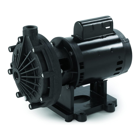
UNIVERSAL BOOSTER PUMP INSTALLATION
This booster pump is 3/4 horsepower with a 1.5
service factor producing a minimum of 50 psi at 12 GPM.
1. UNIT LOCATION
Pump should be installed on a firm and level surface.
Unless required by a local code, it need not be bolted
down. Installation should be as close as possible to a
filtered water return line and convenient location for
servicing. NOTE: Booster pump must always be con-
nected to return line on discharge side of filter. Never
connect suction side booster pump ahead of filter. (See
Figure 1).
2. TYPICAL INSTALLATION - HEATER
CONSIDERATION
Suction side of booster pump must be connected to
the return line after the heater. Except on solar installa-
tion, never connect suction side of booster pump ahead
of filter or heater. NOTE: Keep booster pump a mini-
mum of 3 feet from heater.
Figure 2A: Installation with Heater
POOL HEATER
FILTER
SWEEP PUMP
3. INSTALLATION WITH SOLAR HEATER
With or without a gas heater for back-up, when in-
stalling any one of Pentair automatic pool cleaners in a
pool with solar heating, the in-line tee must be installed
on the return line between the filter and the solar
heater. This minimizes the possibilities of an air lock in
the sweep pump each time the solar panel is filled and
assures an ample supply of water. (See Figure 2B).
Figure 2B: Installation with Heater
FROM SOLAR PANEL
TO SOLAR PANEL
POOL HEATER
FILTER
FILTER
PUMP
4. INSTALLATION WITH SPA POOLS
Connect suction side of the booster pump before
spa bypass valve, if your pool is plumbed for a spa
pool. (See Figure 3).
Figure 3: Installation with Pool/Spa Combo
FROM POOL
SPA VALVE
TO POOL
TO POOL
RETURN
TO SPA RETURN
CAUTION: BEFORE MAKING ANY ELECTRICAL
CONNECTION TO EXISTING POWER SOURCES, BE
SURE ALL ELECTRICAL POWER IS OFF.
5. PUMP INLET CONNECTION TO POOL RETURN LINE
Use elbow and reducing bushing if needed on pre-
plumbed installation. Use tee on existing installation.
Connect pump suction to the return line after filter and
heater as follows: Preferably, underneath side
(NEVER ON TOP) of the horizontal return line.
6. INSTALLATION OF PUMP HOSES
a. To install hoses remove adapter from hose kit bag
(P/N 353020) and wrap teflon tape around the 3/4 inch
npt threads of the adapter. A minimum of four revolutions
is required.
b. Screw adapter with teflon tape into the pump out-
let. Torque to 60 inch x lbs.
c. Cut hose to appropriate length. Six (6) feet of
hose has been provided for both the inlet and outlet.
d. Place adapter cap over hose (See Figure 4) and
slide the hose onto the adapter until the hose is flush
against the wall where the threads begin. Heating of
the hose or use of a lubricant may be useful if the hose
is cold.
e. Screw adapter cap and tighten to the adapter to
secure the hose. Torque to 60 in. x lbs.
f. Repeat process for both inlet and outlet of pump.
When routing the hose make sure there are no tight
bends or kinks in the hose.
Figure 4: Installation of Pump Hoses
HOSE
ADAPTER CAP
ADAPTER
PUMP OUTLET
(3/4 IN. NPT)
GROUND
LOCATION
HOSE
(REFERENCE)
PUMP INLET
(3/4 IN. NPT)
BOLT ANCHOR
HOLES
UNIVERSAL BOOSTER PUMP INSTALLATION
7. SPECIFICATIONS
DIMENSIONS:
16" L X 9" W X 11.5" T
MOTOR:
3/4 HP, 60 HERTZ
POWER SUPPLY: 120/240 VAC
11.5" T
16" L
9" W
8. ELECTRICAL CONNECTIONS FOR BOOSTER
PUMP
Pentair Universal Booster Pump is pre-wired to
operate on 230 volts. The motor can also be wired to
operate on 115 volts by making a simple modification
at motor wire connection plate.
BEFORE TURNING ON POWER TO PUMP,
CHECK VOLTAGE AT INTENDED SOURCE BEFORE
MAKING ELECTRICAL CONNECTION. PUMP
MOTOR CAN BE DAMAGED IF CONNECTED TO
WRONG VOLTAGE.
ELECTRICAL WORK SHOULD BE DONE BY A
LICENSED ELECTRICIAN.
CHECK ELECTRICAL CODES FOR REQUIRE-
MENTS IN YOUR LOCAL AREA.
9. SAFETY WARNING
Motor frame should be grounded for swimming pool
installations as specified in Article 680 of the National
Electrical Code. Failure to properly ground motor can
result in serious electrical shock.
10.TIME CLOCK
A separate time clock is recommended. To ensure
proper sequence of filter pump and booster pump, the
time clocks must be reset if power is interrupted.
The automatic pool cleaner must be run for a
length of time necessary to clean the pool, but should
never be allowed to run while filter system is off. This
will result in damaging the booster pump. Running the
automatic pool cleaner without the filter system in oper-
ation will void warranty. The automatic pool cleaner
should start operating one half hour to forty-five min-
utes after the filter pump starts and stop one half hour
to forty-five minutes before the filter pump
stops.
11.MANUAL SWITCH
A manual switch is recommended. It should be
located between the time clock and the booster pump.
This switch eliminates turning the pump off at the time
clock.
12.PUMP SEAL
The booster pump is fitted with a mechanical shaft
seal which is water lubricated and water cooled. If the
pump is run without water this seal will be damaged.
NEVER OPERATE UNLESS FILTER SYSTEM IS ON.
13.SERVICING THE BOOSTER PUMP
Note: This motor is a drip proof motor, but can be
damaged by rainfall, splash or flooding by causing
water to enter the motor.
- To disassemble the booster pump -
1. Turn off booster pump motor and close valves.
2. Unscrew suction line in middle of volute.
3. Loosen nuts and remove bolts between booster
pump volute and seal bracket.
4. On back end of motor remove cap. Use a crescent
wrench or open end wrench to hold shaft from
spinning.
5. Hold wrench and turn impellar counter clockwise
to remove.
- To remove seal -
1. Stand motor on end, using one screwdriver slowly
pry seal out of impellar. Remove seal bracket and
dislodge seal from backside of seal bracket using
hammer and screwdriver.
- To re-assemble the unit -
1. After replacing the necessary parts, re-assemble
by reversing order of steps 1-5 above.
2. Ceramic seat must be perfectly clean of any
foreign objects or dirt. If seat is not clean, it will
cause leakage. The ceramic seat must go in with
the side containing grooves facing into the center
of the rubber gasket, otherwise it will leak.
3. Replace impellar and seals if warped or discolored.
This condition is caused by overheating due to
pump running dry. Smooth surface of ceramic seal
should be parallel to and facing away from back
side of impellar.
4. Silicone backside of metal flange on spring seal,
push down until flush in center of seal bracket.
Be careful not to get silicone on to spring seals
contact surface.
If you have any questions, contact
Pentair Pool Products at 1-800-831-7133
Advertisement

Related Manuals for Pentair Pool Products LA01N


Summary of Contents for Pentair Pool Products LA01N
- Page 1 GROUND stops. LOCATION contact surface. HOSE (REFERENCE) If you have any questions, contact Pentair Pool Products at 1-800-831-7133 4. INSTALLATION WITH SPA POOLS PUMP INLET (3/4 IN. NPT) Connect suction side of the booster pump before BOLT ANCHOR HOLES spa bypass valve, if your pool is plumbed for a spa...
- Page 2 Pentair Pool Products is not responsible for the cost of removal of the unit, damages due to removal, any other expenses...