
Related Manuals for York MILLENNIUM


Summary of Contents for York MILLENNIUM
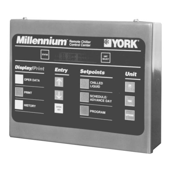
- Page 1 ® MILLENNIUM REMOTE CONTROL CENTER FOR STYLE F AIR-COOLED SCREW CHILLER INSTALL., OPERATION & MAINT. New Release Form 201.18-NM1.2 (300) 28376A EXPANDED USER GUIDE INCLUDED See Section 3...
-
Page 2: Table Of Contents
Checking for Proper Operation................. 11 Refrigeration Cycle ................... 11 System Operating Data Form ................15 Pressure / Temperature Chart ................16 SECTION YORK SERVICES OFFICES..........19 LIST OF FIGURES Fig. Page RCC Wiring Connectionss ..............6 Remote Control Center Installation Details ..........7 Printer Wiring .................. -
Page 3: Section 1 Rcc Hardware And Setup
A communications cable must connect the chiller to The Remote Control Center can not the remote panel. This cable should be a twisted pair be used with a Millennium ISN Sys- shielded cable, type Alpha 4562, Beldon 9320, or tem. -
Page 4: Communications
POWER LOSS PARTS LIST FOR RCC OPTION - YCAS CHILLER In the event of a power loss to the Remote Control Cen- QTY. DESCRIPTION YORK PART NO. REMARKS ter, the microprocessor in the chiller control panel will RCC Unit 371-02485-102... - Page 5 5 minutes, local chiller setpoints (those pro- tween the chiller MicroComputer Control Center and grammed at the chiller panel) will command the chiller. the Remote Control Center has been lost. This loss of YORK INTERNATIONAL...
-
Page 6: Rcc Wiring Connectionss
LD02734 FIG. 1 – RCC WIRING CONNECTIONS... -
Page 7: Remote Control Center Installation Details
LD02733 FIG. 2 – REMOTE CONTROL CENTER INSTALLATION DETAILS... -
Page 8: Printer
957012582. Cost is $10. Note: Prices reflect 1999 and may change with time. Printer specs: Default settings are 1200 Baud, 8 data bits, no parity, 1500 character buffer. Replacement paper: Std. LD02722 FIG. 3 – PRINTER WIRING YORK INTERNATIONAL... -
Page 9: Section 2 Rcc Operation
DISCH LIMITING (discharge pressure has reached the programmable ‘discharge pressure unload’ setpoint) * A copy of this manual is provided with each chiller. Extra manuals can be obtained through the (York) Bal- SUCT LIMITING (suction temperature has reached a timore Parts Center, Baltimore MD. Ph 1-800-9321701. -
Page 10: System Operating Data
They should in the IOM near pages 107-110. Troubleshooting guide is found near pages 140-142. then be reviewed by a competent technician for ab- normal trends or parameters. YORK INTERNATIONAL... -
Page 11: Section 3 Refrigeration Overview
The refrigerant ‘change of state,’ as it changes from liquid to vapor, then back to liquid, is the key compo- nent in this heat transfer process. How is this accom- plished? A simplified answer is given. YORK INTERNATIONAL... - Page 12 This objective is to further cool the main condenses into a liquid. (Visible through the sys- stream of liquid refrigerant being fed to the TXV. tem sight glass). This adds more load capacity to the system (at high loads only). YORK INTERNATIONAL...
-
Page 13: Refrigerant Flow Diagram
- Air Entering Compressor R-22 - Refrigerant Circuit Number Thermostatic Expansion Valve Solenoid Valve Replaceable Core Filter Drier Solenoid Valve Sight Glass Angle Stop Valve Balance Valve Relief Valves LD05019 FIG. 4 – YCAS F REFRIGERANT FLOW DIAGRAM YORK INTERNATIONAL... -
Page 14: System Data Monitored By Rcc
Compressor Info. MC % FLA HOURS STARTS EVAP PUMP CH.W RUN TIME STATUS CH.W SV STEP 0 - 75 On / Off WYE-DELTA On / Off LCHLT ˚F RCHLT ˚F LD05446 FIG. 5 – SYSTEM DATA MONITORED BY RCC YORK INTERNATIONAL... -
Page 15: System Operating Data Form
ON / OFF 2 ECON TXVSOL STATUS ON / OFF 1 FAN STAGE __________________________ 2 FAN STAGE __________________________ 1 COMPRESSOR HEATER ON / OFF 2 COMPRESSOR HEATER ON / OFF 1 WYE-DELTA ON / OFF 2 WYE-DELTA ON / OFF YORK INTERNATIONAL... -
Page 16: Pressure / Temperature Chart
148.4 Vapor entering compressor should be superheated 12-15°F. 153.2 Liquid from condenser should be subcooled 12-15°F. Econo- 158.2 mizer heat exchanger will provide up to an additional 20-28°F 163.2 of sub-cooling when in operation. 168.4 YORK INTERNATIONAL... -
Page 17: Vapor-Compression Refrigeration Cycle
FORM 201.18-NM1.2 LD05447 FIG. 6 – VAPOR-COMPRESSION REFRIGERATION CYCLE YORK INTERNATIONAL... - Page 18 This page intentionally left blank. YORK INTERNATIONAL...
-
Page 19: Section 4 York Services Offices
(502) 499-6020 YORK International Corp. (206) 251-9145 CANADA Ottawa, Ontario Toronto, Ontario Laval, Quebec (613) 596-9111 (905) 890-6812 (514) 387-6000 YORK Applied Systems field office listing subject to change. See us on the web at http://www.york.com/ for additional information. YORK INTERNATIONAL... - Page 20 Proud Sponsor of the 2000 U.S. Olympic Team 36USC380 P.O. Box 1592, York, Pennsylvania USA 17405-1592 (717) 771-7890 Subject to change without notice. Printed in USA Copyright © by York International Corporation 2000 www.york.com ALL RIGHTS RESERVED Form 201.18-NM1.2 (300)