Table of Contents
Advertisement
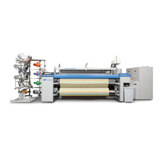
Thank you for purchasing the JAT810 Air Jet Weaving Machine.
This instruction manual describes the correct installation, operating principles, function, adjustment, and maintenance of
the JAT810 motions, all of which should be familiar to all personnel concerned.
Before operating, adjusting, or maintaining the JAT810, be sure to read this manual carefully to understand the JAT810.
Introduction:
This manual is edited separately to provide instructions for towel looms. It consists of Machine and
Electrical Parts. For items not covered herein, refer to the "Instruction Manual" for the standard looms
(hereafter called Standard Machine "Instruction Manual".)
Especially for matters related to safety, please first read Section S of the Standard
Machine "Instruction Manual".
As to the contents of the items described in both of the two above-said manuals, give priority to this
towel manual.
Specifications, operating instructions, and dimensions in this manual are subject to change for improvements without
prior notice.
TOYOTA shall take no responsibility for loss, damage, expense or claims for bodily injury or property damage arising
from incorrect usage which is not in accordance with the instructions given in this manual.
In no event will TOYOTA be liable for products resulting from the use of this machine.
TOYOTA AIR JET
WEAVING MACHINE
Model JAT810
Towel Loom
Advertisement
Table of Contents

Related Manuals for Toyota JAT810


Summary of Contents for Toyota JAT810
- Page 1 This instruction manual describes the correct installation, operating principles, function, adjustment, and maintenance of the JAT810 motions, all of which should be familiar to all personnel concerned. Before operating, adjusting, or maintaining the JAT810, be sure to read this manual carefully to understand the JAT810. Introduction: This manual is edited separately to provide instructions for towel looms.
-
Page 2: Table Of Contents
Contents M1. Preparation for Setting ㌀ ㌀ ㌀ ㌀ ㌀ ㌀ ㌀ ㌀ ㌀ ㌀ ㌀ ㌀ ㌀ ㌀ ㌀ ㌀ ㌀ ㌀ ㌀ ㌀ ㌀ ㌀ ㌀ ㌀ ㌀ ㌀ ㌀ ㌀ ㌀ ㌀ ㌀ ㌀ ㌀ ㌀ ㌀ ㌀ ㌀ ㌀ ㌀ ㌀ ㌀ ㌀ ㌀ ㌀ ㌀ ㌀ ㌀ ㌀ ㌀ ㌀ ㌀ ㌀ ㌀ ㌀ ㌀ ㌀ ㌀ ㌀ ㌀ ㌀ ㌀ ㌀ ㌀ ㌀ ㌀ ㌀ ㌀ ㌀ ㌀ ㌀ ㌀ ㌀ ㌀ ㌀ ㌀ ㌀ ㌀ ㌀ ㌀ ㌀ ㌀ ㌀ ㌀ ㌀ ㌀ ㌀ ㌀ ㌀ ㌀ ㌀ ㌀ ㌀ ㌀ ㌀ ㌀ ㌀ ㌀ ㌀ ㌀ ㌀ ㌀ ㌀ ㌀ ㌀ ㌀ ㌀ ㌀ ㌀ ㌀ ㌀ ㌀ [1] Yarn Beam Installation ㌀... - Page 3 M6. Torsion Back ㌀ ㌀ ㌀ ㌀ ㌀ ㌀ ㌀ ㌀ ㌀ ㌀ ㌀ ㌀ ㌀ ㌀ ㌀ ㌀ ㌀ ㌀ ㌀ ㌀ ㌀ ㌀ ㌀ ㌀ ㌀ ㌀ ㌀ ㌀ ㌀ ㌀ ㌀ ㌀ ㌀ ㌀ ㌀ ㌀ ㌀ ㌀ ㌀ ㌀ ㌀ ㌀ ㌀ ㌀ ㌀ ㌀ ㌀ ㌀ ㌀ ㌀ ㌀ ㌀ ㌀ ㌀ ㌀ ㌀ ㌀ ㌀ ㌀ ㌀ ㌀ ㌀ ㌀ ㌀ ㌀ ㌀ ㌀ ㌀ ㌀ ㌀ ㌀ ㌀ ㌀ ㌀ ㌀ ㌀ ㌀ ㌀ ㌀ ㌀ ㌀ ㌀ ㌀ ㌀ ㌀ ㌀ ㌀ ㌀ ㌀ ㌀ ㌀ ㌀ ㌀ ㌀ ㌀ ㌀ ㌀ ㌀ ㌀ ㌀ ㌀ ㌀ ㌀ ㌀ ㌀ ㌀ ㌀ ㌀ ㌀ ㌀ ㌀ ㌀ ㌀ ㌀ ㌀ ㌀ ㌀ ㌀ ㌀ ㌀ ㌀ ㌀ ㌀ [1] Advance Adjustment ㌀...
- Page 4 [3.2] Tension calibration / zero adjustmentLower let-off (ground let-off) ㌀ ㌀ ㌀ ㌀ ㌀ ㌀ ㌀ ㌀ ㌀ ㌀ ㌀ ㌀ ㌀ ㌀ ㌀ ㌀ ㌀ ㌀ ㌀ ㌀ ㌀ ㌀ ㌀ ㌀ ㌀ ㌀ ㌀ ㌀ ㌀ ㌀ ㌀ ㌀ ㌀ ㌀ ㌀ ㌀ ㌀ [4] RAM clear (data initialization) ㌀...
-
Page 5: M1. Preparation For Setting
M1. Preparation for Setting M1. Preparation for Setting [1] Yarn Beam Installation [1.1] Gland beam installation (1) [Installation on the yarn beam gear side] Mark the yarn beam 1 85 mm from side “a” with a felt-tipped pen, etc. (2) Screw in a yarn beam flange 2 from direction A. Set the inside of the flange to the marked position. - Page 6 M1. Preparation for Setting (5) [Flange installation on the side of the counteryarn beam gear] Mark the yarn beam 1 at a point the reed drawing width of L mm to the right of the marking made in (1). NOTE: A minimum effective drawing width to each nominal reed width is a nominal reed width minus 70 cm.
-
Page 7: [1.2] Pile Beam Installation
M1. Preparation for Setting [1.2] Pile beam installation 1) [Mounting a yarn beam gear side] (1) Standard case (using a flange ring) (1) Make a mark on 110 mm away from the side a of yarn beam 1 with a felt pen or something similar. - Page 8 M1. Preparation for Setting (2) Not using a flange ring (setting a left flange to the left side) (1) Make a mark on the position to fix a flange with a felt pen or something similar. (2) Screw-in yarn beam flange 2 from the direction of "A"...
- Page 9 M1. Preparation for Setting 2) [Mounting a flange opposite to the yarn beam gear side] (5) Make a mark on "Drawing-in width – (2 × Selvage textural width) + 0 to 10 mm" = L mm from the right side on the mark made in step (1). NOTE: The minimum effective drawing-in width relative to each drawing-in width is -70 cm.
-
Page 10: [1.3] Bearing Installation
M1. Preparation for Setting [1.3] Bearing installation (1) Mark the point A below from inside a bearing shaft 9: (2) Insert a bearing 10 to the bearing shaft 9. (3) Insert a hoop 11 so as to have the inside of the bearing 10 matches the marking made in (1). -
Page 11: Preparation Of The Beam
M1. Preparation for Setting [2] Preparation of the Beam [2.1] Preparation of gland beam Wind the gland beam 1 counterclockwise from the beam gear side A. Care should be taken for the direction of winding of the gland beam 1 and pile beam 2 which run counter to each other. -
Page 12: How To Run The Warps And Woven Fabric Through
M1. Preparation for Setting [3] How to Run the Warps and Woven Fabric Through (1) How to run the gland warps through Run the warps to a gland warp dropper 2 via a torsion bar roller 1. Allow them to pass between a pile warp dropper 3 to reach a heald 11 and a reed (2) How to run the pile warps through Run the warps along a deflector roller 4 and via a... - Page 13 M1. Preparation for Setting [4] How to Remove/Reinstall the P-tension Shaft forEasier New Fabric Weaving At the new fabric weaving, removing top cross rail 1, back roller 5, and P-tension shaft 6 makes it easier to set the reed, heald frames, and droppers to the weaving machine. The reed, heald frames and droppers are very heavy, so take extra care when handling them.
-
Page 14: M2. Shedding Motion
M2. Shedding Motion M2. Shedding Motion [1] Dobby Shedding Specifications For basic handling method, please refer to Stäubli’s Instruction Manual. [1.1] Setting the Heald Frame Heightand Shed Size See “Appendix 6. Stäubli’s Positive Dobby (Type S3220)” for the shed size setting procedures.This section introduces the following reference values for the towel looms. - Page 15 M2. Shedding Motion Reference setting value list Table M2-1 Shedding lever Pile Leno weave Waste selvage Ground Dimension A Dimension A Dimension A Dimension A Dimension C Dimension C Dimension C Dimension C Frame No. Frame height Frame height Frame height Frame height (mm) (mm)
-
Page 16: Electronic Shedding Specifications
M2. Shedding Motion [2] Electronic Shedding Specifications For basic handling guidelines, follow the instruction manual for the electronic shedding system. [2.1] Setting the Heald Frame Height and Shedding Amount For the shedding amount setting procedure, refer to the instruction manual for the electronic shedding system. This section shows the following towel specifications as reference values. -
Page 17: Jacquard Shedding Specifications
M2. Shedding Motion [3] Jacquard Shedding Specifications Refer to the instruction manual of Jacquard shedding motion for the handling method. [3.1] Height of Top Rail Bracket (1) Loosen a nut 4. (2) Loosen a bolt 2. (3) Turn an adjust bolt 3 and adjust a height A of a top rail bracket 1. -
Page 18: M3. Temple
M3. Temple M3. Temple Movable temple A moving cloth fell produces pile. NOTE: To make the temple movement smooth, a bearing 4 is installed to a temple base bracket 3. Accordingly, check that all thetemple guides 5 are constantly in contact with the bearing 4 [1] Longitudinal Position of the Temple (1) Set the crank angle to 0°... -
Page 19: Crosswise Position Of The Temple
M3. Temple [2] Crosswise Position of the Temple [2.1] Left-hand side of the loom (1) Loosen the bolts 2 (8 bolts) of a temple case 1. (2) Move the temple case 1 so that a clearance “a” between the left-hand side A of a temple ring 3 and a gripper 4 becomes 0.5 mm. -
Page 20: Vertical Position Of The Temple
M3. Temple [3] Vertical Position of the Temple (1) Adjust the height of the left- and right-hand temples with the number of the shims 1 between a temple bracket 2 and the temple base 3. Adjust the number of shims by loosening 8 bolts on the left-hand side and 6 bolts on the right-hand side. -
Page 21: Vertical Position Of The Temple Cover
M3. Temple [5] Vertical Position of the Temple Cover (1) Loosen a bolt 3. (2) Make the top face A of the temple cover 1 flush with the top face B of the temple cover 2. (3) Tighten the bolt 3 to fix the temple cover. Never operate the loom during the above work. -
Page 22: Periodic Maintenance Of Temple Base
M3. Temple NOTE: Decide the length of fell plate 1 according to the weaving width, and then cut and remove the rest. Finish the section smooth with tools such as a file to prevent persons from injury or a yarn from getting stuck. [7] Periodic Maintenance of Temple Base A rolling bearing is used to smoothly move the temple base in the longitudinal direction. -
Page 23: M4. Selvaging Machine
M4. Selvaging Machine M4. Selvaging Machine [1] Leno Weave with Two Clockers Install a leno weave selvage motion to two heald frames for dobby weave specification or connect it to a harness for jacquard weave specification. With the up and down motion of the heald frames A and B, cross yarns form the selvage texture by moving to the left and right to a stationary yarn 3 which is placed through the eye of a part 2. -
Page 24: [1.1] Installation Of Clocker
M4. Selvaging Machine [1.1] Installation of Clocker (1) Lock the emergency stop pushbutton switch. (2) Install the clockers 1 and 2 to the heald frames A and B. NOTE: A maximum shedding amount of the clockers for a 330 mm center mail is 95 cm. -
Page 25: [1.2] How To Run The Selvage Yarns
M4. Selvaging Machine For multiple tucking jacquard (1) Metal fitting number 1 is applied to stabilize the right and left position of leno weave with two clockers Model number J5211-02010-00 PLATE, KLOCKER 4 pcs/place [1.2] How to Run the Selvage Yarns (1) Run a yarn from a bobbin 1 through a bobbin stand 2 and then through the thread eye via tenser (2) Pass the yarn from the thread eye 4 through the... -
Page 26: [1.3] Yarns For Leno Weave Selvagingmotion
M4. Selvaging Machine [1.3] Yarns for Leno Weave SelvagingMotion (1) Since leno weave has a number of yarn crossings, fine yarns of good quality and high tenacity with lesser fluffs and knots should be used as principle. (2) A cotton double (or triple) yarns of a higher count than the warps for plain weave is recommended. (3) If the same yarn as the one for ground weaving may cause insufficient strength, select another yarn whose physical property is as similar as possible. -
Page 27: Trimmed Selvage Motion
M4. Selvaging Machine [2] Trimmed Selvage Motion Located outside the right-hand end of the fabric, the trimmed selvage motion entwines a weft 1 shuttled and several warps 2 for trimmed selvage (yarns from the trimmed selvage stand) to provide the weft with tension to form a fabric of normal woven texture. - Page 28 M4. Selvaging Machine (2) Pass the yarn coming out of the thread eye 4 to a gland drop box 6 (pass through the dropper) through the eye of a tenser spring 5. (3) Guide the yarn coming out of the pile dropper box through a heald 7 and a reed 8;...
-
Page 29: Gripper
M4. Selvaging Machine [3] Gripper This is an auxiliary device for better solidifying the leno weave of selvage by holding the filled yarn ends (lefthand ends). [3.1] Installation Adjustment (1) [Positional relationship with the temple] Determine a clearance “a” between the end face of a temple ring 1 and a gripper holder 2 as 0.5 (2) [Relative position with the reed] Install a reed 3 so that a clearance “b”... -
Page 30: M5. Pile Let-Off
M5. Pile Let-Off M5. Pile Let-Off Features of Towel Loom Pile Let-Off Mechanism (1) Can control pile warps with tension. (2) Can separately set the tension for the pile weave and plain weave. This prevents the pile yarns from floating in the plain weave. (3) Changes tension for the pile or plain weave within a fraction of time. -
Page 31: Outline Of Let-Off Control
M5. Pile Let-Off [2] Outline of Let-off Control (1) Plain weave “a” The beam rotates according to the density data forwarded from the loom’s main controller M. In addition, difference between the set and actual tensions is used for regulating the beam rotation. (2) Pile weave “b”... -
Page 32: Adjustment Of Electronic Terry Motion Type Let-Off Pile Beam
M5. Pile Let-Off [4] Adjustment of Electronic Terry Motion Type Let-off Pile Beam (1) Move a deflection roller 1 to the L.H. side (in the direction of an arrow). (2) Fix the bolt 3 so as to have the side A of a sensor stay 2 becomes flush with the end face of the deflection roller 1. -
Page 33: Assembly Of Pile Tenser Shaft
M5. Pile Let-Off [5] Assembly of Pile tenser shaft In case of remove the Pile tenser shaft, assembly as followings when you change the cloth. (1) Fit tightly the Pile tenser shaft to load cell shaft 2. (2) Assembly to face up the slit part of coupling 3 and the top of bolt 4 to machine back side. - Page 34 M5. Pile Let-Off (4) The pile tenser must install horizontally. (5) Check the tension of pile warp yarn ( Tension of upper beam ) must be 0 on the function panel before apply tension to the pile warp yarn. In case of not 0, to calibrate the tension and adjust to Reffer:Instruction manual E.3 section Electric Components/Let-off Motions for A Towel Loom...
- Page 35 M6. Torsion Back M6. Torsion Back Terry motion follows positively helped by the easing rod. A passive method is adopted to absorb variation in the yarn path length caused by the shedding with the torsion bar. Warp tension is absolutely controlled with a load cell. [1] Advance Adjustment [1.1] Tentative Adjustment (1) Slacken the warp tension on the gland beam (to 0...
- Page 36 M6. Torsion Back For safety, release the torsion of the torsion bar 6 completely. ・Make sure that a notch 5 points at 0 in a scale 1 and that the tension roller can be rocked back and forth with hand. Ensure to follow the procedures below to prevent the warm from any damage.
- Page 37 M6. Torsion Back [2] Adjustment at the Change of Gland Warp Tension (1) Loosen the bolt 2. (2) Turn the warm 4. For standard, turn the warm by 5° on the scale to a tension of 50 kg. (3) Tighten the bolt 2. (4) Enter a desired set tension from the function panel and press the gland warp tension return switch.
- Page 38 M6. Torsion Back [4] Height Adjustment If the height of torsion back is changed, the height of dropper box also changes. (1) Loosen a bolt 9 of a dropper box bracket 8 and a nut 11 of an adjust bolt 10. To lower the height, loosen the adjust bolt 10 and widen the clearance between the frame.
- Page 39 M7. Warp Stop Device M7. Warp Stop Device ■ Warp stop device (dropper box) The dropper box is located above the warp line in the rear of a loom. If a warp is cut, the dropper drops to energize a contact bar 3. The signal is transmitted to the loom control box via a contact plate 4 and cable 5 to stop the loom operation.
- Page 40 M7. Warp Stop Device [2] Vertical Position The standard vertical position shall be 1 to 2 mm between the gland yarn and the oval tube and 4 to 5 mm between the pile yarn and the oval tube. Adjustment may be made with the number of shim 14 or by making vertical adjustment of a dropper box bracket 8.
- Page 41 M7. Warp Stop Device [2.2] Adjustment of vertical position ofdropper box bracket (1) Lock the emergency stop pushbutton switch. (2) Loosen the fixing bolts 9 and 10. (3) Remove a bolt 6. (4) Loosen a nut 12 and adjust the height with an adjust bolt 11.
- Page 42 M8. Lubrication M8. Lubrication NOTE: This section describes the lubrication points specific to the towel loom. The descriptions do not include those points lubricated by a one-point lubrication device. Lubricate the points described here in addition to those described in the Standard Machine “Instruction Manual.” Always use lubricant recommended by this company.
- Page 43 M8. Lubrication Lubricating intervals 10 hours Every 10 days Every 1.5 to 2.0 months at warp beam change Electric centrallzed lubrication Lubricating points Grease gun Oiler Brush Grease gun Oiler Brush system Upper beam pinion (left-hand side) RH cutter (mechanical) cutter bracket mid point RH cutter (mechanical) cutter bracket mid point RH cutter (mechanical) cutter bracket mid point (Bearing periphery and guide plates)
- Page 44 M8. Lubrication Lubricating intervals 10 hours Every 10 days Every 1.5 to 2.0 months at warp beam change Electric centrallzed lubrication Lubricating points Grease gun Oiler Brush Grease gun Oiler Brush system Pile easing shaft BKT < Cloth roller take-up drive system : 054K On the machine take-up φ 700 specification >...
- Page 45 M8. Lubrication [2] Oil Change of Terry Motion Cam Box (1) Oil type and replacement period are as follows: (Standard lubrication quantity is 8 liters.) Reference: Type: Oil B #150 (Mobilgear 600 XP 150, etc.) Replacement period: Once a year after the initial replacement (2) Drain used oil by inserting a drain tool into the drain port.
- Page 46 M9. Electronic Terry Motion M9. Electronic Terry Motion This section describes the mechanical points of the electronic terry motion. The related electrical details are given in Section E6. [1] Adjusting the Stoppers Adjust the stoppers (there is once each at the RH and LH sides) according to the steps below. (1) Set the crank angle at 0°...
- Page 47 M9. Electronic Terry Motion [2] Zero-point Restoration Proximity Switch Do not disturb the zero-point restoration proximity switch which has been adjusted in TOYOTA. If the proximity switch setting is changed, adjust the switch according to the steps below. (1) Set the MANUAL–AUTO switch in the inverter servo amplifier box to the MANUAL position.
- Page 48 M9. Electronic Terry Motion [3] Reverse Current Absorber Cover NEVER touch the reverse current absorber cover when the machine is in operation or shortly after the machine comes to a stop. The cover is HOT! [4] Lubrication of Terry Motion Gear Box The oil type and oil change interval are the same as the main gearing box.
- Page 49 E1. Setting of Towel Loom-related Function Panel E1. Setting of Towel Loom-related Function Panel Refer to “0.3 Detailed Explanation of Function Panel” of the Standard Machine “Instruction Manual” for the basic handling procedure of the function panel. [1] Towel Screen Setting Method Touch the [ Map ] –...
- Page 50 E1. Setting of Towel Loom-related Function Panel [1.4] Sheet counter for test pattern weaving NOTE: Displayed for the dobby specification only. [ OFF ] The number of sheets is not counted during test pattern weaving. Set to OFF when a test pattern is used for test or waste weaving. [ ON ] The number of sheets is counted for test pattern weaving.
- Page 51 E1. Setting of Towel Loom-related Function Panel [For the electronic dobby] ・Note that the loom stops once and restarts automatically if the selected pattern for extra weaving is not a weaving pattern. [For the Jacquard] ・The loom is switched to ground weaving only operation mode without stop.
- Page 52 E1. Setting of Towel Loom-related Function Panel [1.6] Setting the warp manual stop position Select the warp manual stop position during pile weaving. In the initial setting, the loom stops at L2 pick. Change the setting if any alteration in organization is desired.
- Page 53 E1. Setting of Towel Loom-related Function Panel [2] How to Set [ PILE ] [2.1] Electronic dobby specification Touch the [ Map ] – [ Pattern ] icon to display the screen shown at left. Se the pile, border and take-up stop required for weaving on this screen.
- Page 54 E1. Setting of Towel Loom-related Function Panel Pile-Length: Input the pile length. Input the terry motion operating length for the pick. The screen at left shows an example of 10.0 mm pile with a gap of 2.0 mm for 3-pick pile. Take-Stop: Select take-up or stop.
- Page 55 E1. Setting of Towel Loom-related Function Panel [3] Pattern Initialization [Operator] At the center of the screen, the initialization switch and the current position are displayed. When you want to start a pattern from the first step, press the [PATTERN 1ST] switch shown at left. The message "Do you want to initialize the patter?"...
- Page 56 E1. Setting of Towel Loom-related Function Panel Setting for Machine Speed Switch When you touch the [Map]-[Motor] icon, the setting items shown at left will be displayed. When you want to set different machine speeds for pile and boarder sections respectively Set [Machine speed switch] to [ON].
- Page 57 E1. Setting of Towel Loom-related Function Panel For the towel specification, the setting item of [Yarn speed control (for machine speed change)] shown at left is provided under the [TwCtrl] setting. If the machine speed always changes for highly-loaded weaving such as Jacquard weaving, standard Tw control (stabilization of the insertion angle) may not be stabilized.
- Page 58 E2. Setting and Operation of Towel Loom Beam-relatedFunction Panel E2. Setting and Operation of Towel Loom Beam- relatedFunction Panel Touch the [ Map ] – [ Letoff ] icon. [1] Setting for bottom beam control In the two-stage tension specifications, set the tension for border weaving higher than that of pile weaving.
- Page 59 E2. Setting and Operation of Towel Loom Beam-relatedFunction Panel [2] Setting for top beam control (1) Warp tension (for boarder and ground weavings) For the Jacquard newCAN specification, individually input tensions for ground and border weavings respectively. For the other specifications, any setting for ground weaving is not displayed. Input tension to border, when ground weaving, border ground weaving, borderweaving are set.
- Page 60 E2. Setting and Operation of Towel Loom Beam-relatedFunction Panel [3] Setting for beam change Touch the [ Operator ] – [ Beam Change ] icon to display the screen shown at left. (1) [ BOTTOM BEAM ] switch Press this switch for setting upon bottom beam replacement.
- Page 61 E2. Setting and Operation of Towel Loom Beam-relatedFunction Panel [4] Yarn beam operation from function panel Touch the Manual page through [ Map ] – [ Lefoff ] to display the screen shown at left. The top and bottom beams and the take-up motion can be operated manually.
- Page 62 E2. Setting and Operation of Towel Loom Beam-relatedFunction Panel [5] Operation of Forward/Reverse BeamRotation Switch on the L.H. Frame Two switches are located on the upper beam frame on the L.H. frame as shown in the figure to the left. When the switch is turned clockwise, the beam rotates in forward direction while the switch is being turned.
- Page 63 E3. Electric Components / Let-off Motions for A Towel Loom E3. Electric Components / Let-off Motions for A Towel Loom ■ Ground let-off / pile let-off / take-up motionsUpper and lower let-off motions LETOFF 1 inside the main control box is for the ground let-off and take-up motion.
- Page 64 E3. Electric Components / Let-off Motions for A Towel Loom Components of the let-off / take-up controller 1).LETOFF1(Ground let-off, take-up) DIP switch Servo amplifier Heat sink Connector (CN1) DC power line Connector (CN2) Signal line in the control box Connector (CN3) Load cell signal line Connector (CN4) Communication line...
- Page 65 E3. Electric Components / Let-off Motions for A Towel Loom 2).LETOFF2(Pile let-off) Let-off servo amplifier board Heat sink Connector (CN1) DC power line Connector (CN2) Signal line in control box Connector (CN3) Load cell signal line Connector (CN4) Communication line Connector (CN5) Resolver cable line Connector (CN7)
- Page 66 E3. Electric Components / Let-off Motions for A Towel Loom LED display and check pins 1) LETOFF1(Ground let-off, take-up) In normal In abnormal Board LED No. Name Color Main cause for error status status LED1 Yellow CPU error monitor Blinking ON, OFF Fault or runaway of CPU LED2...
- Page 67 E3. Electric Components / Let-off Motions for A Towel Loom 2) LETOFF2(Pile let-off) In normal In abnormal Pile let-off LED No. Name Color Main cause for error status status LED1 Yellow CPU error monitor Blinking ON, OFF Fault or runaway of CPU LED2 Let-off servo alarm Faulty servo amplifier...
- Page 68 E3. Electric Components / Let-off Motions for A Towel Loom [3] Setting the standard let-off tension In any of the following cases, set the basic let-off tension according to the let-off tension calibration and zero adjustment procedure. ・ When “WARP TENSION CALUBRATION NECESSARY”...
- Page 69 E3. Electric Components / Let-off Motions for A Towel Loom [3.2] Tension calibration / zero adjustmentLower let-off (ground let-off) (1) Read the scale 1 of the torsion back and record it. (2) Rotate the lower beam forward until the dropper lowers to the end.
- Page 70 E3. Electric Components / Let-off Motions for A Towel Loom [4] RAM clear (data initialization) Clear the RAM according to the procedure shown below. “Clearing the RAM” is normally unnecessary. After clearing the RAM, be sure to calibrate and restore the tension. NOTE: Since all data set in the LET-OFF mode on the function panel are lost, save the data on the memory card or take a memo before the following operation.
- Page 71 E3. Electric Components / Let-off Motions for A Towel Loom How to set the DIP switches When setting the DIP switches on the servo amplifiers, refer to the lists shown below. ■ Ground let-off, take-up DIP switches(SW1,SW2) Density Motor capacity Standard density 500W ON ON...
- Page 72 E3. Electric Components / Let-off Motions for A Towel Loom [6] Troubleshooting Ground let-off motion, pile let-off motion If LED3 (yellow) on the servo amplifier board is not blinking follow the flow shown below.
- Page 73 This system is referred to as "Classic type". Serial system (JAT810 system) This system is referred to as "new CAN type" NOTE:The conventional parallel system is also available for JAT810. ・Difference between the parallel and serial systems Item Serial system...
- Page 74 Instrumentation and Electronic Jacquard for Towel Weaving Machine PICK Data [3.1] Classic Type Notes: 1.In this section, the interface circuit indicates the number 0 when a transistor is turned ON (energized). However, your actual screen may display either □ or ■ instead of 0 or 1. For information about which type is being used, contact your shedding motion manufacture.
- Page 75 Instrumentation and Electronic Jacquard for Towel Weaving Machine A-15) Take-up stop A-15 Significance Take-up stop ON Take-up stop OFF A-16) Sheet counter A-16 Significance Sheet counter ON Sheet counter OFF A-17) Border control A-17 Significance Machine speed (Low) Machine speed (High) A-18) Single pile A-18...
- Page 76 Instrumentation and Electronic Jacquard for Towel Weaving Machine A-22) Pile position H A-24 A-23 A-22 Significance A-23) Pile position M Loose pick 1 for long/short piles A-24) Pile position L Loose pick 1 Loose pick 2 Fast pick 1 Fast pick 2 Fast pick 3 Loose pick 3 Loose pick 4...
- Page 77 Instrumentation and Electronic Jacquard for Towel Weaving Machine [3.2] new CAN type The PICK data design format varies depending on your Jacquard manufacturer. Check the instruction manual issued by your Jacquard manufacture. The following shows the latest PICK data provided by the major Jacquard manufacturers.
- Page 78 Instrumentation and Electronic Jacquard for Towel Weaving Machine < BONAS JACQUARD > < STAUBLI JACQUARD > Function Function Pile position signal 1 Pile length signal 1 Pile position signal 2 Pile length signal 2 Pile position signal 3 Pile length signal 3 Pile position signal 4 Pile length signal 4 Pile length signal 1...
- Page 79 Instrumentation and Electronic Jacquard for Towel Weaving Machine (1) Color signal □ □ □ □ No-load weave ■ □ □ □ Color 1 □ ■ □ □ Color 2 ■ ■ □ □ Color 3 □ □ ■ □ Color 4 ■...
- Page 80 Instrumentation and Electronic Jacquard for Towel Weaving Machine (6) Ground weaving / pile signal □ □ □ □ 3-pick pile ■ □ □ □ 4-pick pile □ ■ □ □ 5-pick pile ■ ■ □ □ 6-pick pile □ □ ■ □ 7-pick pile ■...
- Page 81 Instrumentation and Electronic Jacquard for Towel Weaving Machine (9) Pile length signal □ □ □ □ Pile length index(0) ■ □ □ □ Pile length index(1) □ ■ □ □ Pile length index(2) ■ ■ □ □ Pile length index(3) □...
- Page 82 Instrumentation and Electronic Jacquard for Towel Weaving Machine (10) Density signal TYPE.A (Indirect input type) For Terry Loom This type is used for the towel specification. Specify an index for a desired setting value in the same way as the pile length, tension, and machine speed settings.
- Page 83 Instrumentation and Electronic Jacquard for Towel Weaving Machine [4] Setting on the FP screen When a Jacquard design format is designed, an index system where you set values for the following items on the loom FP, is used. This index system makes it easier to change values, so it is convenient when you need to frequently fine adjust set values for towel weaving.
- Page 84 Instrumentation and Electronic Jacquard for Towel Weaving Machine [4.1] Description on the [Map]-[Jacquard]-[Setting] screen For the new CAN design (in the case of a signal created in [3-2] mentioned above) [Jacquard] Normally, set to [Use]. Design data is read from the Jacquard to run the loom. When [Not use] is selected, pattern data inside the loom is used for operation.
- Page 85 Instrumentation and Electronic Jacquard for Towel Weaving Machine [Pile length] (Unit: mm) *2 a.When the pile length signals are com- posed of indexes (0) to (7) ・The pile lengths set for [0] to [7] are used for weaving. ・The value set for [L1-L2 (0-7)] is added to the L2 pile length.
- Page 86 Instrumentation and Electronic Jacquard for Towel Weaving Machine [Pile tension] *2 a.When the pile tension signals are composed of indexes (1) to (3) ・The upper beam tension is changed to a set tension. ・Use this setting when you want to set a different tension for each texture such as long/short pile.
- Page 87 Instrumentation and Electronic Jacquard for Towel Weaving Machine For the Classic design (in the case of signals created in [3-1] mentioned above) [Jacquard] Same as the new CAN design in 1) mentioned above. [Density] There are eight setting items that correspond to the densities (0) to (7) for A-9) to -11).
- Page 88 Instrumentation and Electronic Jacquard for Towel Weaving Machine [4.2] Description on the [Map]-[Jacquard]-[Manual] screen [Leveling] When [Highest point] or [Lowest point] is selected and the loom is operated in inching, all harnesses will be leveled upward or downward. To release it, press the selected button again.
- Page 89 Instrumentation and Electronic Jacquard for Towel Weaving Machine [4.3] Description on the [Map]-[Jacquard]-[Value] screen The history of pattern communication with the Jacquard is displayed. The number of a pattern requested does not correspond to that of a <Ready Not Off> pattern received.
- Page 90 Instrumentation and Electronic Jacquard for Towel Weaving Machine [4.4] The history of pattern communication with the Jacquard The data shown at left is based on the situation where a pattern from a current position to the next 12 picks is received and the data for the first 12 lines that were displayed upon opening the window is going to be used for a pattern to be woven.
- Page 91 Instrumentation and Electronic Jacquard for Towel Weaving Machine [4.5] Warning messages related to the Jacquard The operation disable signal is input from the Jacquard 2451 Jacquard: Emergency stop controller. Check the Jacquard controller. Loom-side input port: IO1-CN37-A2 The sheet counter stop signal is received from the Jacquard 2440 Jacquard: Weaving completed controller.
- Page 92 Instrumentation and Electronic Jacquard for Towel Weaving Machine [5] [APPENDIX] EXAMPLE FOR INPUTTING TENSION ABSOLUTE VALUES TYPE B (absolute input type) For non Terry Loom This input type is used for the specifications other than the towel specification. Density information is designed at the time of design designing.
- Page 93 Instrumentation and Electronic Jacquard for Towel Weaving Machine Density Density Signal Signal value value 50.0 □ □ ■ □ ■ ■ ■ ■ ■ □ □ □ 75.0 □ ■ ■ ■ □ ■ ■ ■ □ ■ □ □ 50.1 ■...
- Page 94 Instrumentation and Electronic Jacquard for Towel Weaving Machine Density Density Signal Signal value value 120.0 □ □ □ □ ■ ■ □ ■ □ □ ■ □ 130.0 □ □ ■ □ ■ □ □ □ ■ □ ■ □ 120.1 ■...
- Page 95 Instrumentation and Electronic Jacquard for Towel Weaving Machine Density Density Signal Signal value value 160.0 □ □ □ □ □ □ ■ □ □ ■ ■ □ 170.0 □ □ ■ □ □ ■ □ ■ □ ■ ■ □ 160.1 ■...
- Page 96 Instrumentation and Electronic Jacquard for Towel Weaving Machine Density Density Signal Signal value value 200.0 □ □ □ □ ■ □ ■ ■ ■ ■ ■ □ 210.0 □ □ ■ □ ■ ■ □ □ □ □ □ ■ 200.1 ■...
- Page 97 Instrumentation and Electronic Jacquard for Towel Weaving Machine Density Density Signal Signal value value 240.0 □ □ □ □ □ ■ ■ □ ■ □ □ ■ 250.0 □ □ ■ □ □ □ ■ ■ ■ □ □ ■ 240.1 ■...
- Page 98 E5. Electronic Terry Motion E5. Electronic Terry Motion [1] LEDs and Switches in the Inverter Box (See the drawing given on the next page) PL1 ZERO POSITION LED ON when the terry motion is in the zero position. PL2 ZERO POSITION ALARM LED ON when the servomotor zero position is lost, e.g., due to the disconnected resolver line.
- Page 99 E5. Electronic Terry Motion ■ Location of LEDs and Switches in the Inverter Box ZERO POS. ZERO POS. ALARM BATTERY ALARM MANUAL−AUTO An inverter box has a high-voltage area and the voltage FWD−REV. does not immediately decrease even if the power is ALARM RESET turned off.
- Page 100 E5. Electronic Terry Motion ■ Servo Amplifier You can check the operating state, alarm, etc. with the display unit. Use the MODE switch to change the display area. Use the up/down switch to change the menu within the area. Do not touch the SEL and SET switches. The internal setting data may be damaged.
- Page 101 E5. Electronic Terry Motion 【Display area and area menu】...
- Page 102 E5. Electronic Terry Motion 【Details of status display area】 Status display menu Symbol Range and unit Description Displays the motor speed. The symbol blinks in reverse rotation. Motor speed ±99999 min When the speed reaches or exceeds ±10,000 min-1, the symbol will not be displayed, and all digits will blink in reverse rotation.
- Page 103 E5. Electronic Terry Motion ■ How to Check the Effective Load Ratio bL ・ In the initial display state, keep pressing ▼ until " bL___" is displayed. ・ Check the maximum value during terry motion operation. [2] Installation Powering on the weaving machine after wiring between the machine and the inverter box will turn on the ZERO POSITION ALARM LED (PL2) located in the inverter box, as well as displaying alarm 23 or 32 on the servo amplifier 7-segment display.
- Page 104 E5. Electronic Terry Motion [3] Servo Motor Replacement After the servo motor is replaced, the ZERO POSITION ALARM LED turns on as in the case of [2]. Perform the following zero point preset operation as well as the zero point registering operation. ■...
- Page 105 E5. Electronic Terry Motion [4] Adjustment (1) FWD-REV movement in manual operation 1.Set the MANUAL-AUTO switch to the MANUAL position. 2.Use the FWD-REV switch to move the cloth fell only. NOTE: If you move it excessively in the FWD or REV direction, the mechanical overrun protector will work for safety, showing alarm 16 or 18 on the servo amplifier...
- Page 106 E5. Electronic Terry Motion [6] Troubleshooting NOTE: Do not touch the SET button on the servo amplifier in the inverter box. Doing so may damage the internal settings. (1) If the “Terry motion Alarm” message appears on the function panel and the machine will not run (The yellow lamp of the signal indicator flashes): Any alarm code on the servo amplifier operation display in the inverter box? ↓YES...
- Page 107 E5. Electronic Terry Motion ■ Alarmlist Alarm Alarm name Detecting method Cause and counter measures AL01 Over-current (OC) IPM of the power supply detected following 1.Short circuit or grounding of armature wire (U, V, or W) troubles. 2.Ambient temperature is higher than 55 degrees Celsius. (Model 035P or lower versions can detect 1 Above problems are likely.
- Page 108 E5. Electronic Terry Motion Alarm Alarm name Detecting method Cause and counter measures AL14 Brake error(BERR) 1.When the dynamic brake is used, brake Read the descriptions on the dynamic and holding brake output turning ON did not generate the connections and check the wiring and used accessories. brake confirmation signal input.3 2.When the holding brake is used, brake output turning ON kept the brake...
- Page 109 E5. Electronic Terry Motion Alarm Alarm name Detecting method Cause and counter measures AL24 Resolver ABS battery The ABS battery voltage dropped Replace the ABS battery immediately. alarm (BAL) below 3.2V. The zero point setting is no longer saved. Reset the absolute position. AL25 Terry motion error ・Zero-point restoration was executed in...
- Page 110 E5. Electronic Terry Motion (2) If the “Abnormal terry volume” message appears on the function panel (The yellow lamp of the signal indicator flashes), it means that: The pile length is too long, or so many entries of length (A)+ or (B)+ are made in pattern instructions. Correct the pattern.
- Page 111 E5. Electronic Terry Motion (6) If the cloth fell has not returned to the zero position for ground weave: 1.Set the MANUAL-AUTO switch to the AUTO Zero-point restoration position. 2.Carry out the zero-point restoration. ・If this operation has returned the cloth fell to the Set the MANUAL-AUTO zero point, check the wiring between the servo switch to MANUAL.