Table of Contents
Advertisement
Thank you for purchasing the JAT810 Air Jet Weaving Machine.
This instruction manual describes the correct installation, operating principles, function, adjustment, and
maintenance of the JAT810 motions, all of which should be familiar to all personnel concerned.
Before operating, adjusting, or maintaining the JAT810, be sure to read this manual carefully to understand
the JAT810.
Introduction:
This manual is edited separately to provide instructions for towel looms. It consists of
Machine and Electrical Parts. For items not covered herein, refer to the "Instruction Man-
ual" for the standard looms (hereafter called Standard Machine "Instruction Manual".)
Especially for matters related to safety, please first read Section S of the Standard
Machine "Instruction Manual".
As to the contents of the items described in both of the two above-said manuals, give pri-
ority to this towel manual.
Specifications, operating instructions, and dimensions in this manual are subject to change for improvements
without prior notice.
TOYOTA shall take no responsibility for loss, damage, expense or claims for bodily injury or property damage
arising from incorrect usage which is not in accordance with the instructions given in this manual.
In no event will TOYOTA be liable for products resulting from the use of this machine.
JUNE, 2010 Ver. 2.01
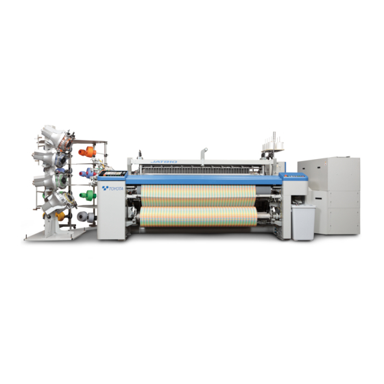
TOYOTA AIR JET
WEAVING MACHINE
Towel Loom
Model JAT810
(FIRST EDITION)
(Towel)
Advertisement
Table of Contents

Related Manuals for Toyota JAT810


Summary of Contents for Toyota JAT810
- Page 1 This instruction manual describes the correct installation, operating principles, function, adjustment, and maintenance of the JAT810 motions, all of which should be familiar to all personnel concerned. Before operating, adjusting, or maintaining the JAT810, be sure to read this manual carefully to understand the JAT810.
-
Page 2: Table Of Contents
CONTENTS Section 1 Mechanical Section 2 Electrical M1. Preparation for Setting ..................M1-1 Yarn Beam Installation Preparation of the Beam How to Run the Warps and Woven Fabric Through How to Remove/Reinstall the P-tension Shaft for Easier New Fabric Weaving M2. - Page 3 M8. Lubrication ......................M8-1 Lubrication Cycle and Applicable Fluids Oil Change of Terry Motion Cam Box Oil Change of Jacquard Bevel Gearbox M9. Electronic Terry Motion..................M9-1 Adjusting the Stoppers Zero-point Restoration Proximity Switch Reverse Current Absorber Cover Lubrication of Terry Motion Gear Box E1.
-
Page 4: M1. Preparation For Setting
Section 1 Mechanical Section 1 Mechanical M1. Preparation for Setting Yarn Beam Installation [ 1 ] Gland beam installation (1) [Installation on the yarn beam gear side] Mark the yarn beam 1 90 mm from side “a” with a felt-tipped pen, etc. (2) Screw in a yarn beam flange 2 from direction A. - Page 5 M1. Preparation for Setting (5) [Flange installation on the side of the counter- yarn beam gear] Mark the yarn beam 1 at a point the reed drawing width of L mm to the right of the mark- ing made in (1). NOTE: A minimum effective drawing width to each nominal reed width is a nominal reed width minus 70 cm.
- Page 6 Section 1 Mechanical [ 2 ] Pile beam installation (1) [Installation on the side of the yarn beam gear] Mark the yarn beam 1 107.5 mm from the side “a” with a felt-tipped pen, etc. (2) Screw in the yarn beam flange 2 from direction A.
- Page 7 M1. Preparation for Setting (5) [Flange installation on the side of the counter- yarn beam gear] Mark the yarn beam 1 at L mm [reed drawing width minus (2* selvage texture width) plus 0 to 10 mm] to the right of the marking made in (1).
-
Page 8: Preparation Of The Beam
Section 1 Mechanical Preparation of the Beam [ 1 ] Preparation of gland beam Wind the gland beam 1 counterclockwise from the beam gear side A. Care should be taken for the direction of wind- ing of the gland beam 1 and pile beam 2 which run counter to each other. -
Page 9: How To Run The Warps And Woven Fabric Through
M1. Preparation for Setting How to Run the Warps and Woven Fabric Through (1) How to run the gland warps through Run the warps to a gland warp dropper 2 via a torsion bar roller 1. Allow them to pass between a pile warp dropper 3 to reach a heald 11 and a reed 12. -
Page 10: How To Remove/Reinstall The P-Tension Shaft For Easier New Fabric Weaving
Section 1 Mechanical How to Remove/Reinstall the P-tension Shaft for Easier New Fabric Weaving At the new fabric weaving, removing top cross rail 1, back roller 5, and P-tension shaft 6 makes it eas- ier to set the reed, heald frames, and droppers to the weaving machine. - Page 11 M1. Preparation for Setting Clean the pile yarn contact part on the board pane l and th e g uide bar a t eve ry b eam change, and confirm that no foreign substance is attached. (This is to avoid a thread being adhered by a substance such as paste that adversely affects and tension.) M1 - 8...
-
Page 12: M2. Shedding Motion
Section 1 Mechanical M2. Shedding Motion Dobby Shedding Specifications For basic handling method, please refer to Stäubli’s Instruction Manual. 2.1.1 Setting the Heald Frame Height and Shed Size See “Appendix 6. Stäubli’s Positive Dobby (Type S3220)” for the heald frame height and shed size setting procedures. -
Page 13: Jacquard Shedding Specifications
M2. Shedding Motion Jacquard Shedding Specifications Refer to the instruction manual of Jacquard shedding motion for the handling method. 2.2.1 Height of Top Rail Bracket (1) Loosen a nut 4. (2) Loosen a bolt 2. (3) Turn an adjust bolt 3 and adjust a height A of a top rail bracket 1. -
Page 14: M3. Temple
Section 1 Mechanical M3. Temple Movable temple A moving cloth fell produces pile. NOTE: To make the temple movement smooth, a bearing 4 is installed to a temple base bracket 3. Accord- ingly, check that all thetemple guides 5 are constantly in contact with the bearing 4 Longitudinal Position of the Temple (1) Set the crank angle to 0°... -
Page 15: Crosswise Position Of The Temple
M3. Temple Crosswise Position of the Temple [ 1 ] Left-hand side of the loom (1) Loosen the bolts 2 (8 bolts) of a temple case 1. (2) Move the temple case 1 so that a clearance “a” between the left-hand side A of a temple ring 3 and a gripper 4 becomes 0.5 mm. -
Page 16: Vertical Position Of The Temple
Section 1 Mechanical Vertical Position of the Temple (1) Adjust the height of the left- and right-hand temples with the number of the shims 1 between a temple bracket 2 and the temple base 3. Adjust the number of shims by loosening 8 bolts on the left-hand side and 6 bolts on the right-hand side. -
Page 17: Vertical Position Of The Temple Cover
M3. Temple Vertical Position of the Temple Cover (1) Loosen a bolt 3. (2) Make the top face A of the temple cover 1 flush with the top face B of the temple cover 2. (3) Tighten the bolt 3 to fix the temple cover. Never operate the loom during the above work. -
Page 18: M4. Selvaging Machine
Section 1 Mechanical M4. Selvaging Machine Leno Weave with Two Clockers Install a leno weave selvage motion to two heald frames for dobby weave specification or connect it to a harness for jacquard weave specification. With the up and down motion of the heald frames A and B, cross yarns form the selvage texture by moving to the left and right to a stationary yarn 3 which is placed through the eye of a part 1. - Page 19 M4. Selvaging Machine For multiple tucking jacquard Jacquard (1) Metal fitting number 1 is applied to stabilize the harness right and left position of leno weave with two clockers Model number J5211-02010-00 PLATE, KLOCKER 4 pcs/place 4.1.2 How to Run the Selvage Yarns (1) Run a yarn from a bobbin 1 through a bobbin stand 2 and then through the thread eye via tenser 3.
-
Page 20: Trimmed Selvage Motion
Section 1 Mechanical 4.1.3 Yarns for Leno Weave Selvaging Motion (1) Since leno weave has a number of yarn cross- ings, fine yarns of good quality and high tenac- ity with lesser fluffs and knots should be used as principle. (2) A cotton double (or triple) yarns of a higher count than the warps for plain weave is recom- mended. - Page 21 M4. Selvaging Machine 4.2.1 Installation, Adjustment, and Preparatory Operation Use a cheese on the trimmed selvage stand as the yarn for trimmed selvage. A total of six cheeses excluding a cheese for the leno weave selvage will be used for the trimmed selvage. [ 1 ] How to run the trimmed selvage yarns through (1) Hook a yarn from cheese 9 to rod 3 through...
- Page 22 Section 1 Mechanical (4) Guide the yarn coming out of the pile dropper box through a heald 7 and a reed 8; entwine it with a weft at the cloth fell. The yarn will run through a temple 9 and be cut with the RH cut- ter.
-
Page 23: Gripper
M4. Selvaging Machine Gripper This is an auxiliary device for better solidifying the leno weave of selvage by holding the filled yarn ends (left- hand ends). 4.3.1 Installation Adjustment (1) [Positional relationship with the temple] Determine a clearance “a” between the end face of a temple ring 1 and a gripper holder 2 as 0.5 mm. -
Page 24: M5. Pile Let-Off
Section 1 Mechanical M5. Pile Let-Off Features of Towel Loom Pile Let-Off Mechanism (1) Can control pile warps with tension. (2) Can separately set the tension for the pile weave and plain weave. This prevents the pile yarns from floating in the plain weave. (3) Changes tension for the pile or plain weave within a fraction of time. -
Page 25: Outline Of Let-Off Control
M5. Pile Let-Off Outline of Let-off Control (1) Plain weave “a” The beam rotates according to the density data forwarded from the loom’s main controller M. In addition, difference between the set and actual tensions is used for regulating the beam rotation. -
Page 26: Adjustment Of Easing Roller
Section 1 Mechanical Adjustment of Easing Roller (1) Set the crank angle to 0° in the fast pick. (2) Lock the emergency stop pushbutton switch (3) Check that a dimension A is 104 mm (stan- dard set dimension). To adjust the dimension A, loosen a bolt 5. NOTE: Should uneven pile be generated, Make the dimension A longer evenly. -
Page 27: M6. Torsion Back
M6. Torsion Back M6. Torsion Back Terry motion follows positively helped by the easing rod. A passive method is adopted to absorb variation in the yarn path length caused by the shedding with the tor- sion bar. Warp tension is absolutely controlled with a load cell. Advance Adjustment 6.1.1 Tentative Adjustment... - Page 28 Section 1 Mechanical (6) Match to the shedding timing in the plain weave state. (Standard is 310°.) In the pile weave state, produce a state where a temple 12 is closest to a reed 13. (7) Rewind the beam from the function panel and tighten the warp tension to a set value.
-
Page 29: Adjustment At The Change Of Gland Warp Tension
M6. Torsion Back (9) Check that the indicator 9 points at between –5 and +15 of the scale 10 during operation (including pile weaving). If the indicator 9 points at elsewhere, loosen the bolt 2 and turn the warm 4 to make adjust- ment. -
Page 30: Height Adjustment
Section 1 Mechanical Height Adjustment If the height of torsion back is changed, the height of dropper box also changes. (1) Loosen a bolt 9 of a dropper box bracket 8 and a nut 11 of an adjust bolt 10. To lower the height, loosen the adjust bolt 10 and widen the clearance between the frame. -
Page 31: M7. Warp Stop Device
M7. Warp Stop Device M7. Warp Stop Device Warp stop device (dropper box) The dropper box is located above the warp line in the rear of a loom. If a warp is cut, the dropper drops to energize a contact bar 3. The signal is transmitted to the loom control box via a contact plate 4 and cable 5 to stop the loom operation. -
Page 32: Vertical Position
Section 1 Mechanical Vertical Position The standard vertical position shall be 1 to 2 mm between the gland yarn and the oval tube and 4 to 5 mm between the pile yarn and the oval tube. Adjustment may be made with the number of shim 14 or by making vertical adjustment of a dropper box bracket 8. -
Page 33: M8. Lubrication
M8. Lubrication M8. Lubrication NOTE: This section describes the lubrication points specific to the towel loom. The descriptions do not include those points lubricated by a one-point lubrication device. Lubricate the points described here in addition to those described in the Standard Machine “Instruction Man- ual.”... - Page 34 Section 1 Mechanical Every 1.5 to 2.0 months 10 hours Every 10 days Lubricating intervals at warp beam change Electric centrallzed Grease Grease Lubricating points Oiler Brush Oiler Brush lubrication system Pile yarn beam gear (left-hand side) Upper beam pinion (left-hand side) RH cutter (mechanical) cutter bracket mid point Electric winding gear M8 - 2...
- Page 35 M8. Lubrication Every 1.5 to 2.0 months 10 hours Every 10 days Lubricating intervals at warp beam change Electric centrallzed Grease Grease Lubricating points Oiler Brush Oiler Brush lubrication system Movable temple, bearing Torsion bar guide voller Pile easing shaft BKT (2) Dobby For the lubrication points, type of fluid and lubrication cycle, follow the instruction manual for the dobby loom.
-
Page 36: Oil Change Of Jacquard Bevel Gearbox
Section 1 Mechanical Oil Change of Terry Motion Cam Box (1) Oil type and replacement period are as fol- lows: (Standard lubrication quantity is 8 liters.) Reference: Type: Oil B #150 (Mobil 629, etc.) Replacement period: Once a year after the initial replacement (2) Drain used oil by inserting a drain tool into the drain port. -
Page 37: M9. Electronic Terry Motion
M9. Electronic Terry Motion M9. Electronic Terry Motion This section describes the mechanical points of the electronic terry motion. The related electrical details are given in Section E6. For the Mechanical Terry Motion, refer to Section M5. Adjusting the Stoppers Adjust the stoppers (there is once each at the RH and LH sides) according to the steps below. -
Page 38: Zero-Point Restoration Proximity Switch
Section 1 Mechanical Zero-point Restoration Proximity Switch Do not disturb the zero-point restoration proximity switch which has been adjusted in TOYOTA. If the proximity switch setting is changed, adjust the switch according to the steps below. (1) Set the MANUAL–AUTO switch in the inverter servo amplifier box to the MANUAL position. -
Page 39: Reverse Current Absorber Cover
M9. Electronic Terry Motion Reverse Current Absorber Cover NEVER touch the reverse current absorber cover (located between the control box and the RH frame) when the machine is in operation or shortly after the machine comes to a stop. The cover is HOT! Lubrication of Terry Motion Gear Box The oil type and oil change interval are the same as... - Page 40 The following table outlines the comparative indication of the color of the indicator lamps, their lighted or blink- ing state and the mode display of the function panel. (The colors of the indicator lamps are the standard colors set forth by Toyota.) ...
-
Page 41: E1. State Of Indicator Lamps And Mode Display
E1. State of Indicator Lamps and Mode Display Indicator lamp Remarks Mode display Color State Control section Blinking Failure LET-OFF(UPPER): SERVO AMPLIFIER EXCESS SPEED Upper let-off ABNORMAL control LET-OFF(UPPER): SERVO AMPLIFIER RESOLVER ERROR LET-OFF(UPPER): SERVO AMPLIFIER SHORT TIME OVERLOAD LET-OFF(UPPER): SERVO MOTOR OVERHEAT (SOFT) LET-OFF(UPPER): SERVO AMPLIFIER SPEED AMPLIFIER SATURATION LET-OFF(UPPER): SERVO AMPLIFIER OVERCURRENT... - Page 42 Section 2 Electrical Setting of Towel Loom-related Function Panel Refer to “0.3 Detailed Explanation of Function Panel” of the Standard Machine “Instruction Manual” for the basic handling procedure of the function panel. Towel Screen Setting Method Touch the [ Map ] – [ Towel ] icon to display the screen shown in the bottom at left.
-
Page 43: E2. Setting Of Towel Loom-Related Function Panel
E2. Setting of Towel Loom-related Function Panel (2) Cutting when [ PRELIMINARY WEAVE STOP ] is selected. The following cutting operation will be made: Operator Loom 1) When the cutting number reaches the set cutting number, extra weaving operation starts. •... - Page 44 Section 2 Electrical (3) Cutting [ Cut stop ] The following cutting operation will be made: Operator Loom 1) Weaves a piece of extra woven pattern after weaving a number of cutting pieces in a towel pattern. [In case of Jacquard] Weaves according to the extra weaving pattern from Jacquard.
- Page 45 E2. Setting of Towel Loom-related Function Panel [ 4 ] Setting the warp manual stop position Select the warp manual stop position during pile weaving. In the initial setting, the loom stops at L2 pick. Change the setting if any alteration in organization is desired.
-
Page 46: How To Set [ Pile ]
Section 2 Electrical How to Set [ PILE ] [ 1 ] Electronic dobby specification Touch the [ Map ] – [ Pattern ] icon to display the screen shown at left. Se the pile, border and take-up stop required for weaving on this screen. -
Page 47: Pattern Initialization
E2. Setting of Towel Loom-related Function Panel Pile-Length: Input the pile length. Input the terry motion operating length for the pick. The screen at left shows an example of 10.0 mm pile with a gap of 2.0 mm for 3-pick pile. Take-Stop: Select take-up or stop. - Page 48 Section 2 Electrical Setting and Operation of Towel Loom Beam-related Function Panel Touch the [ Map ] – [ Letoff ] icon. [ 1 ] Setting for bottom beam control In the two-stage tension specifications, set the ten- sion for border weaving higher than that of pile weaving.
-
Page 49: E3. Setting And Operation Of Towel Loom Beam-Related Function Panel
E3. Setting and Operation of Towel Loom Beam-related Function Panel The value should be around 0.4. If pile defects occur in the 1st to 5th rows after switching to pile weaving, increase the value at intervals of 0.1. If pile is normally produced at first but pile defects occur in any rows from the 3rd, 4th or 5th, decrease the value at intervals of 0.1. - Page 50 Section 2 Electrical [ 3 ] Setting for beam change Touch the [ Operator ] – [ Beam Change ] icon to display the screen shown at left. (1) [ BOTTOM BEAM ] switch Press this switch for setting upon bottom beam replacement.
- Page 51 E3. Setting and Operation of Towel Loom Beam-related Function Panel [ 4 ] Yarn beam operation from function panel Touch the Manual page through [ Map ] – [ Lefoff ] to display the screen shown at left. The top and bottom beams and the take-up motion can be operated manually.
- Page 52 Section 2 Electrical [ 5 ] Operation of Forward/Reverse Beam Rotation Switch on the L.H. Frame Two switches are located on the upper beam frame on the L.H. frame as shown in the figure to the left. When the switch is turned clockwise, the beam rotates in forward direction while the switch is being turned.
-
Page 53: E4. Electric Components / Let-Off Motions For A Towel Loom
E4. Electric Components / Let-off Motions for A Towel Loom Electric Components / Let-off Motions for A Towel Loom Electric Components Upper and lower let-off motions The controllers of the bottom- and top-mounted let- 1 off motions are integrated in main control box 1. Servo amplifier board 2 controls the lower let-off motion (ground let-off motion). - Page 54 Section 2 Electrical [ 2 ] LED display and check pins LED2 CK10 IC26 LED3 C222 LED1 C262 REC1 R311 C263 R301 C264 R300 CN10 U2 V2 W2 LED No. Name Color Normal Error Major error cause Error detection by servo amplifier LED1 CHARGE Main circuit power monitor...
- Page 55 E4. Electric Components / Let-off Motions for A Towel Loom [ 3 ] Setting the standard let-off tension In any of the following cases, set the basic let-off tension according to the let-off tension calibration and zero adjustment procedure. • When “WARP TENSION CALUBRATION NEC- ESSARY”...
- Page 56 Section 2 Electrical (5) Measure the warp beam diameter at operation restart and enter it on the [ FIXER ] – [ WARP ] screen. (6) Start tension restoration. Touching the tension restoration switch 11 starts the tension restoration. [ 3.2 ] Tension calibration / zero adjustment Upper let-off (pile let-off) (1) Read the scale...
- Page 57 E4. Electric Components / Let-off Motions for A Towel Loom [ 4 ] RAM clear (data initialization) Clear the RAM according to the procedure shown below. “Clearing the RAM” is normally unnecessary. After clearing the RAM, be sure to calibrate and restore the tension. NOTE: Since all data set in the LET-OFF mode on the function panel are lost, save the data on the memory card or take a memo before the following operation.
- Page 58 Section 2 Electrical [ 5 ] Method for setting DIP switches (SW1 and SW2) Set the DIP switches (SW1 and SW2) on the servo amplifier according to the table below. DIP switch (SW1): For setting the loom specification and servo motor capacity DIP switch (SW2): For setting let-off and take-up ...
- Page 59 E4. Electric Components / Let-off Motions for A Towel Loom [ 6 ] Troubleshooting For the bottom- and top-mounted let-off motions If LED3 (yellow) on the servo amplifier board is not blinking follow the flow shown below. LED3 is: Turn off and on the power. Is LED3 blinking? Is 5VDC for check pin CK1...
- Page 60 Section 2 Electrical Instrumentation and Electronic Jacquard for Towel Weaving Machine [ 1 ] Jacquard Controller Refer to the instruction manual issued by the manufacturer of the shedding motion. [ 2 ] About the Electrical Signal to be used for Pattern Generation Notes: 1 When a transistor is turned ON (energized), the interface circuit indicates “0”.
-
Page 61: E5. Instrumentation And Electronic Jacquard For Towel Weaving Machine
E5. Instrumentation and Electronic Jacquard for Towel Weaving Machine A–12) Ground weave and pile H A–13) Ground weave and pile M A–14) Ground weave and pile L A-12) A-13) A-14) Significance 3-pick pile 4-pick pile 5-pick pile 6-pick pile Preliminary weave No-load weave Border Ground weave... - Page 62 Section 2 Electrical A-19) Pile length H A-20) Pile length M A-21) Pile length L Effective for an electronic type terry motion specifications. A-19) A-20) A-21) Significance A : Pile length A A+ : Step length is increased from the previous length. A–...
-
Page 63: E6. Electronic Terry Motion
E6. Electronic Terry Motion Electronic Terry Motion [ 1 ] LEDs and Switches in the Inverter Box (See the drawing given on the next page) ZERO POSITION LED ON when the terry motion is in the zero position. ZERO POSITION ALARM LED ON when the servomotor zero position is lost, e.g., due to the discon- nected resolver line. - Page 64 Section 2 Electrical Location of LEDs and Switches in the Inverter Box ZERO POS. ZERO POS. ALARM BATTERY ALARM MANUAL−AUTO An inverter box has a high-voltage area and FWD−REV. the voltage does not immediately decrease even if the power is turned off. When you open ALARM RESET the door, turn off the power, wait at least 3 min- ZERO POS.
- Page 65 E6. Electronic Terry Motion [ 2 ] Installation Powering on the weaving machine after wiring between the machine and the inverter will turn on the ZERO POSITION ALARM LED (PL2) located in the inverter box, as well as displaying alarm 23 or 32 on the servo amplifier 7-segment display.
- Page 66 Section 2 Electrical [ 3 ] Adjustment (1) FWD-REV movement in manual operation 1) Set the MANUAL-AUTO switch to the MAN- UAL position. 2) Use the FWD-REV switch to move the cloth PL1 PL3 PL2 fell only. NOTE: If you move it excessively in the FWD SS1 SS2 BS2 BS1 or REV direction, the mechanical overrun pro- tector will work for safety, showing alarm 16 or...
- Page 67 E6. Electronic Terry Motion [ 5 ] Troubleshooting NOTE: Do not touch the SET button on the servo amplifier in the inverter box. Doing so may damage the internal settings. (1) If the “Terry motion Alarm” message appears on the function panel and the machine will not run (The yel- low lamp of the signal indicator flashes): Any alarm code on the servo amplifier 7-segment display in the inverter box? 1) If the CHARGE LED (red) of the servo ampli-...
- Page 68 Section 2 Electrical Alarmlist Alarm Alarm name Detecting method Cause and counter measures AL01 Over-current (OC) IPM of the power supply 1. Short circuit or grounding of armature wire (U, V, detected following troubles. or W) (Model 035P or lower versions can 2.
- Page 69 E6. Electronic Terry Motion Alarm Alarm name Detecting method Cause and counter measures AL14 Brake error(BERR) 1. When the dynamic brake is used, Read the descriptions on the dynamic and holding brake output turning ON did not brake connections and check the wiring and used generate the brake confirmation accessories.
- Page 70 Section 2 Electrical Alarm Alarm name Detecting method Cause and counter measures AL25 Option alarm Option board alarm. The wiring between the machine and servo (CPALM) amplifier is broken or its connection is faulty. The zero-point restoration has failed. Try again. The jacquard power is off.
- Page 71 E6. Electronic Terry Motion (2) If the “Abnormal terry volume” message appears on the function panel (The yellow lamp of the signal indicator flashes), it means that: The pile length is too long, or so many entries of length (A)+ or (B)+ are made in pattern instructions. Correct the pattern.
- Page 72 Section 2 Electrical [ 6 ] Comparison with the Mechanical Terry Motion (1) The electronic terry motion has no terry proximity switch. Consequently, it is possible to initialize patterns at any pick. (The crank angle is about 300°.) (2) When the pile beam is replaced in the electronic terry motion, you do not need to check the pile beam condition on the function panel or modify the pile length.
- Page 73 E6. Electronic Terry Motion [ 7.3 ] DIP Switch Use this to update programs for the substrate. Normal mode (1: On, 2: Off) Keep this state under the normal condition. Write mode (1: Off, 2: Off) Set 1 to Off to write a program from a memory card. Return it to the normal mode after finishing writing.