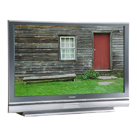
Mitsubishi Electric WD-52527 Service Manual
Lcd projection hdtv
Hide thumbs
Also See for WD-52527:
- Owner's manual (109 pages) ,
- Service manual (86 pages) ,
- Quick reference manual (4 pages)
Table of Contents
Advertisement
Quick Links
MITSUBISHI ELECTRIC
WD-52327
WD-52527
CAUTION:
Before servicing this chassis, it is important that the service person read the "SAFETY PRECAUTIONS" and
"PRODUCT SAFETY NOTICE" contained in this manual.
• Power Input
• Power Usage
• Light Engine
• Light Source
• Channel Range
• Antenna Input
• Tuning
• Cabinet Dimensions
• Weight
• Speakers (8 Ohms 10W)
• Design specifications are subject to change without notice.
MITSUBISHI DIGITAL ELECTRONICS AMERICA, INC.
All manuals and user guides at all-guides.com
SPECIFICATIONS
: AC 120V, 60Hz
: 295W
: 3 LCD (1280 x 720 pixels)
: 110W
: Air VHF - 2~13, UHF - 14~69
Analog Cable - 1~25
Digital Cable - 1~35
: 2 RF 75Ω unbalanced
: 1 NTSC/ATSC/QAM
1 Out of Band for CableCARD
1 NTSC for PIP
: [WD-52527 / WD-52528]
34"(H) x 49.6"(w) x 17.8"(D)
: WD-62527 / WD-62528
40.5"(H) x 58.3"(W) x 19.9"(D)
: [WD-52527 / WD-52528]
110 lbs
: [WD-62527 / WD-62528]
133 lbs
: 2-5 ½ x 2 ¼ inch
9351 Jeronimo Road, Irvine, CA 92618-1904
Copyright © 2005 Mitsubishi Digital Electronics America, Inc.
All Rights Reserved
Ser
Ser
Ser vice
Ser
Ser
Manual
Manual
Manual
Manual
Manual
LCD PROJECTION HDTV
V28 CHASSIS
V28 Chassis
WD-52527
WD-62527
• Input Level
TM
• Output Level
• Digital
Pb Solder
.
vice
vice
vice
vice
V28+ Chassis
WD-52528
WD-62528
Pb Solder
: VIDEO IN JACK (RCA Type)
1.0Vp-p 75W unbalanced
: AUDIO IN JACK (RCA Type)
-4.7dBm 43kW unbalanced
: S-VIDEO IN JACK
(Y/C separate type)
Y:1.0 Vp-p C:0.286Vp-p(BURST)
75W unbalanced
: COMP / Y, Cr, Cb (RCA Type)
Y: 1.0 Vp-p Cr, Cb: 700mVp-p
: VIDEO OUT JACK (RCA Type)
1.0Vp-p 75W unbalanced
: AUDIO OUT JACK (RCA Type)
-4.7dBm 4.7kW unbalanced
: IEEE-1394 I/O Jacks
: AC-3 Digital Audio Output
(RCA Type)
TM
: HDMI
: Lead-Free solder PWBs
2005
2005
2005
2005
2005
Advertisement
Table of Contents

Related Manuals for Mitsubishi Electric WD-52527


Summary of Contents for Mitsubishi Electric WD-52527
- Page 1 1 Out of Band for CableCARD Y: 1.0 Vp-p Cr, Cb: 700mVp-p 1 NTSC for PIP • Cabinet Dimensions : [WD-52527 / WD-52528] • Output Level : VIDEO OUT JACK (RCA Type) 34"(H) x 49.6"(w) x 17.8"(D) 1.0Vp-p 75W unbalanced...
- Page 2 All manuals and user guides at all-guides.com...
-
Page 3: Table Of Contents
All manuals and user guides at all-guides.com MODEL: WD-52527 / WD-52528 / WD-62527 / WD-62528 CONTENTS INTRODUCTION ..........................5 PRODUCT SAFETY NOTICE ......................5 SAFETY PRECAUTIONS ......................... 6 DISASSEMBLY ..........................7 Front Cabinet Components ......................7 Chassis Removal ..........................8 Chassis Disassembly / Accessing PWBs .................. - Page 4 All manuals and user guides at all-guides.com MODEL: WD-52527 / WD-52528 / WD-62527 / WD-62528 Fans Power Supply ........................53 Analog Video Signal Path ......................54 Digital Video Signal Path ......................55 Sound Signal Path ........................56 Command Input Circuitry ....................... 57 Serial Data Control Lines ......................
-
Page 5: Introduction
All manuals and user guides at all-guides.com MODEL: WD-52527 / WD-52528 / WD-62527 / WD-62528 INTRODUCTION This service manual provides service instructions for LCD Projection TV Models and Chassis: V28 Chassis V28+ Chassis WD-52527 WD-52528 WD-62527 WD-62528 This service manual includes: 1. -
Page 6: Safety Precautions
All manuals and user guides at all-guides.com MODEL: WD-52527 / WD-52528 / WD-62527 / WD-62528 SAFETY PRECAUTIONS NOTICE: Observe all cautions and safety related notes located inside the receiver cabinet and on the receiver chassis. WARNING: Operation of this receiver outside the cabinet or with the cover removed presents a shock hazard from the receiver's power supplies. -
Page 7: Disassembly
All manuals and user guides at all-guides.com MODEL: WD-52527 / WD-52528 / WD-62527 / WD-62528 CABINET FRONT DISASSEMBLY SPEAKER GRILLE Removal Pull the SPEAKER-GRILLE away from the cabinet to remove. SCREEN-ASSY Removal 1) Remove 10 screws (a) from the upper cabinet rear cover (3 screws on each side and 4 screws across the top). -
Page 8: Chassis Removal
All manuals and user guides at all-guides.com MODEL: WD-52527 / WD-52528 / WD-62527 / WD-62528 CHASSIS REMOVAL BACK-COVER Removal 1) Remove 9 screws (a) 2) Remove 13 screws (b) 3) Pull the COVER-BACK from the cabinet. Metal Support Plate Removal... - Page 9 All manuals and user guides at all-guides.com MODEL: WD-52527 / WD-52528 / WD-62527 / WD-62528 Chassis Mounting Screws Removal Remove the two chassis mounting screws (b). Release Cable Clamps & Disconnect CE Connector Cable Cable Cable Clamp Clamp Clamp Connector...
- Page 10 All manuals and user guides at all-guides.com MODEL: WD-52527 / WD-52528 / WD-62527 / WD-62528 On the right side of the chassis (from the rear): 1) Release the AC Cord from it’s mounting. 2) Unplug ES1 connector to the speakers.
- Page 11 All manuals and user guides at all-guides.com MODEL: WD-52527 / WD-52528 / WD-62527 / WD-62528 Complete Chassis Removal To completely remove the chassis from the cabinet, the folowing connectors must be unplugged. • PL plug to the Ballast (on the left side of the chassis).
-
Page 12: Chassis Disassembly / Accessing Pwbs
All manuals and user guides at all-guides.com MODEL: WD-52527 / WD-52528 / WD-62527 / WD-62528 Chassis Disassembly / Accessing PWBs Note: Although not individually indicated, unplug the required connectors in each disassembly step. Chassis Sequence of Disassembly REMOVE Chassis Top Cover (Fig. - Page 13 All manuals and user guides at all-guides.com MODEL: WD-52527 / WD-52528 / WD-62527 / WD-62528 Chassis Cover Removal (Figure 1) 1) Remove the 4 screws (a). 2) Lift the Cover from the chassis. Figure 1: Chassis Cover Removal Assy PWB- TERMINAL Removal (Figure 2) 1) Remove 7 screws (a) to remove the TERMINAL-INLAY.
- Page 14 All manuals and user guides at all-guides.com MODEL: WD-52527 / WD-52528 / WD-62527 / WD-62528 PWB-POWER Removal (Figure 3) 1) Remove four screws (b). 2) Disconnect all connectors to PWB-POWER. 3) Lift PWB-POWER from the chassis. Chassis Upper Shield Removal (Figure 3) 1) Remove seven screws (c).
- Page 15 All manuals and user guides at all-guides.com MODEL: WD-52527 / WD-52528 / WD-62527 / WD-62528 Chassis Rear Shield Removal (Figure 4) 1) Remove nine screw (c). 2) Remove two nuts (c1). 3) Pull off Chassis Rear Shield. Figure 4: Chassis Rear Shield Removal PWB-MICRO Removal Referring to Figure 5.
- Page 16 All manuals and user guides at all-guides.com MODEL: WD-52527 / WD-52528 / WD-62527 / WD-62528 PWB-RISER and PWB-FORMAT Removal Referring to Figure 6. 1) Remove one screw (e). 2) Unplug and remove PWBs MICRO, RISER and FORMAT. Figure 6: PWBs MICRO, RISER and FORMAT Removal...
-
Page 17: Light Engine Replacement
All manuals and user guides at all-guides.com MODEL: WD-52527 / WD-52528 / WD-62527 / WD-62528 Light Engine Replacement Light Engine and Associated Components The exploded view below shows the the Light Engine and those components attached directly to the Engine. - Page 18 All manuals and user guides at all-guides.com MODEL: WD-52527 / WD-52528 / WD-62527 / WD-62528 Light Engine Replacement Preliminary Refer to the chassis removal procedure and remove the BACK-COVER and Metal Support Plate (page 8) 1) Remove (3) screws (a) from Filter Cover Holder...
- Page 19 All manuals and user guides at all-guides.com MODEL: WD-52527 / WD-52528 / WD-62527 / WD-62528 Light Engine Replacement 5) Remove two screws (c) from Fan Plate and remove 4) Remove one screw (b) securing engine plate and base Fan Plate...
- Page 20 All manuals and user guides at all-guides.com MODEL: WD-52527 / WD-52528 / WD-62527 / WD-62528 10) Remove (4) screws (g) from Lamp Fan Bracket 11 Loosen (2) screws (h) to remove Ballast Cable 12) Disconnect all connectors from Interface PWB and...
- Page 21 All manuals and user guides at all-guides.com MODEL: WD-52527 / WD-52528 / WD-62527 / WD-62528 15) Lift the Engine from Engine plate leaving the Screw (d) Lamp Duct fan, Lamp Duct Intake and Ballast. INSTALLATION 1) Reverse the above steps.
-
Page 22: Servicing The Lenticular Screen And Fresnel Lens
All manuals and user guides at all-guides.com MODEL: WD-52527 / WD-52528 / WD-62527 / WD-62528 SERVICING THE LENTICULAR SCREEN AND FRESNEL LENS CAUTION: Wear gloves when handling the Lenticular Screen and Fresnel Lens. This prevents cuts and finger prints. Do not place Fresnel Lens in the sun. - Page 23 All manuals and user guides at all-guides.com MODEL: WD-52527 / WD-52528 / WD-62527 / WD-62528 Figure 2: BEZEL Removal (Front View) Figure 3: Lenticular Screen & Fresnel Lens Removal (Rear View) Page 23...
-
Page 24: Installation Of The Lenticular Screen And Fresnel Lens
All manuals and user guides at all-guides.com MODEL: WD-52527 / WD-52528 / WD-62527 / WD-62528 SERVICING THE LENTICULAR SCREEN AND FRESNEL LENS Lenticular Screen and Fresnel Lens Installation Note: Store the Lenticular Screen and Fresnel Lens in a cool dry place. High humidity may deform the Lenticular Screen and Fresnel Lens. -
Page 25: Adjustments
All manuals and user guides at all-guides.com MODEL: WD-52527 / WD-52528 / WD-62527 / WD-62528 MENU-2-4-7-0 OPTION MENU OPTION MENU Initializing 1. Press the “MENU” button on the remote hand unit. DTV Port :Auto 2. Press the buttons “2”, “4”, “7” and “0” in order. -
Page 26: Led Indicator Diagnostics
All manuals and user guides at all-guides.com MODEL: WD-52527 / WD-52528 / WD-62527 / WD-62528 AV Reset Defaults Input Com pone nt 1394 HDMI™ A/V Me m ory Ant 1&2 1/2/3 1/2/3* (if conn.) 1&2 TV Contra st Center Center... -
Page 27: Error Codes Operational Check
All manuals and user guides at all-guides.com MODEL: WD-52527 / WD-52528 / WD-62527 / WD-62528 Abnormal LED Indications POWER STATUS LAMP Power Condition Status Yellow Excess Temperature Power Off or On Yellow Usage time over 4000 Hrs. change Blinks Lamp Cover open... -
Page 28: Remote Operational Mode
All manuals and user guides at all-guides.com MODEL: WD-52527 / WD-52528 / WD-62527 / WD-62528 Remote Control Operational Modes There are two Remote Hand Unit Operational Modes, “Standard” and “NetCommand ”. The Remote is initially in the “Standard” mode. The “NetCommand” mode is used when controlling Home Theater devices using NetCommand. -
Page 29: Transferring Data
All manuals and user guides at all-guides.com MODEL: WD-52527 / WD-52528 / WD-62527 / WD-62528 4. Adjustment Selection Use the “VIDEO” button to select a specific elecrtrical ajustment, “1 HPOS” or “2 VPOS”. 5. Adjusting Data After selecting an adjustment item, use the “UP” and “DN” buttons to change adjustment data. -
Page 30: Light Engine Adjustment
All manuals and user guides at all-guides.com MODEL: WD-52527 / WD-52528 / WD-62527 / WD-62528 Light Engine Adjustments Test Signal Activation 1) Press “MENU-2-4-5-7” (Service Mode) 2) Press “REW” (Test Pattern). Red = 4% overscan White = 5% overscan Green = 6% overscan... -
Page 31: Trapezodial Distortion Adjustment
All manuals and user guides at all-guides.com MODEL: WD-52527 / WD-52528 / WD-62527 / WD-62528 Trapezoid Distortion Adjustment 1) Loosen [A-1] and [A-2] so they clear [A-3]. 2) For Distortion at the top of the picture, rotate [A-3] counter clockwise (the picture will move upward). -
Page 32: Hortizontal & Vertical Position
All manuals and user guides at all-guides.com MODEL: WD-52527 / WD-52528 / WD-62527 / WD-62528 Purpose: To center the picture on the screen. [Format Circuit] Symptom: Horizontal/Vertical Position Adjust- Picture is off center. ment Measuring Instrument 1. Press “MENU-2-4-5-7”, to activate the Service Mode.. -
Page 33: Troubleshooting
All manuals and user guides at all-guides.com MODEL: WD-52527 / WD-52528 / WD-62527 / WD-62528 MICRO / TERMINAL PWB TROUBLESHOOTING T roubleshooting Guide Sym ptom Possible Ca use s No audio or video on one input Physical damage on RCA jack, broken... -
Page 34: Power-Pwb
All manuals and user guides at all-guides.com MODEL: WD-52527 / WD-52528 / WD-62527 / WD-62528 POWER PWB TROUBLESHOOTING SYMPTOM CHECK POINT POSSIBLE CAUSE Check +15VS @ connector PD pin 1 Check Q9E00 circuit ERROR CODE 51 Check -15VS @ connector PD pin 7... -
Page 35: Optical Engine
All manuals and user guides at all-guides.com MODEL: WD-52527 / WD-52528 / WD-62527 / WD-62528 OPTICAL ENGINE TROUBLESHOOTING Sym ptom Cause W ha t to check FMT does not turn on lamp due to fault Check error code on front pannel. Check problem detection indicated. -
Page 36: Protect Lines
All manuals and user guides at all-guides.com MODEL: WD-52527 / WD-52528 / WD-62527 / WD-62528 LAMP PROTECT LINE COVER-DET LAMP_PROT. Emergency Status Voltage Indicators code Comment [CD] (Device+Menu) (KA/pin 14) Normal Engaged 2.46 V condition Turns OFF Lamp: 1.64 V... -
Page 37: Using Lead Free Solder
All manuals and user guides at all-guides.com MODEL: WD-52527 / WD-52528 / WD-62527 / WD-62528 Using Lead Free Solder Pb Solder • The flux is more corrosive. • The time required for a good solder connection may The above symbol indicates Lead (Pb) Free solder was take longer. -
Page 38: Chip Parts Replacement
All manuals and user guides at all-guides.com MODEL: WD-52527 / WD-52528 / WD-62527 / WD-62528 CHIP PARTS REPLACEMENT Some resistors, shorting jumpers (0 Ohm resistors), Chip Parts Removal (Transistors) ceramic capacitors, transistors and diodes are chip parts. 1. Melt the solder of one lead and lift the side of The following precautions should be taken when replacing that lead upward. -
Page 39: Replacement Parts
All manuals and user guides at all-guides.com MODEL: WD-52527 / WD-52528 / WD-62527 / WD-62528 REPLACEMENT PARTS Parts Ordering To expedite delivery of replacement parts orders, specify the following: Model Number/Serial Number Part Number and description Quantity Note: Unless complete information is supplied, delay in processing of orders will result. -
Page 40: Quick Reference List
All manuals and user guides at all-guides.com MODEL: WD-52527 / WD-52528 / WD-62527 / WD-62528 QUICK REFERENCE FOR COMMON PARTS MAJOR BOARD ASSEMBLIES Assembly WD-52527/WD-52528 WD-62527/WD-62528 ASSY-PWB-POWER1 930B933001 930B933001 ASSY-PWB-TERMINAL 934C150001 934C150002 ASSY-PWB MICRO 934C151001 934C151001 ASSY-PWB-DM 934C152001 934C152001 ASSY-PWB V28FMT... -
Page 41: Service Parts List
All manuals and user guides at all-guides.com MODEL: WD-52527 / WD-52528 / WD-62527 / WD-62528 [#] Model Legend: [a] WD-52527, [b] WD-52528, [c] WD-62527 [d] WD-62528 Ref # Part # Part Name & Description Ref # Part # Part Name & Description... - Page 42 All manuals and user guides at all-guides.com MODEL: WD-52527 / WD-52528 / WD-62527 / WD-62528 [#] Model Legend: [a] WD-52527, [b] WD-52528, [c] WD-62527 [d] WD-62528 Ref # Part # Part Name & Description Ref # Part # Part Name & Description...
- Page 43 All manuals and user guides at all-guides.com MODEL: WD-52527 / WD-52528 / WD-62527 / WD-62528 [#] Model Legend: [a] WD-52527, [b] WD-52528, [c] WD-62527 [d] WD-62528 Ref # Part # Part Name & Description Ref # Part # Part Name & Description...
- Page 44 All manuals and user guides at all-guides.com MODEL: WD-52527 / WD-52528 / WD-62527 / WD-62528 [#] Model Legend: [a] WD-52527, [b] WD-52528, [c] WD-62527 [d] WD-62528 Ref # Part # Part Name & Description Ref # Part # Part Name & Description...
- Page 45 All manuals and user guides at all-guides.com MODEL: WD-52527 / WD-52528 / WD-62527 / WD-62528 [#] Model Legend: [a] WD-52527, [b] WD-52528, [c] WD-62527 [d] WD-62528 Ref # Part # Part Name & Description Ref # Part # Part Name & Description...
- Page 46 All manuals and user guides at all-guides.com MODEL: WD-52527 / WD-52528 / WD-62527 / WD-62528 [#] Model Legend: [a] WD-52527, [b] WD-52528, [c] WD-62527 [d] WD-62528 Ref # Part # Part Name & Description Ref # Part # Part Name & Description Part No.
- Page 47 All manuals and user guides at all-guides.com MODEL: WD-52527 / WD-52528 / WD-62527 / WD-62528 [#] Model Legend: [a] WD-52527, [b] WD-52528, [c] WD-62527 [d] WD-62528 Ref # Part # Part Name & Description Ref # Part # Part Name & Description Part No.
- Page 48 All manuals and user guides at all-guides.com MODEL: WD-52527 / WD-52528 / WD-62527 / WD-62528 [#] Model Legend: [a] WD-52527, [b] WD-52528, [c] WD-62527 [d] WD-62528 Ref # Part # Part Name & Description Ref # Part # Part Name & Description...
- Page 49 All manuals and user guides at all-guides.com MODEL: WD-52527 / WD-52528 / WD-62527 / WD-62528 [#] Model Legend: [a] WD-52527, [b] WD-52528, [c] WD-62527 [d] WD-62528 Ref # Part # Part Name & Description Ref # Part # Part Name & Description...
-
Page 50: Screen Assembly Parts List
All manuals and user guides at all-guides.com MODEL: WD-52527 / WD-52528 / WD-62527 / WD-62528 [#] Model Legend: [a] WD-52527, [b] WD-52528, [c] WD-62527 [d] WD-62528 Ref # Part # Part Name & Description Ref # Part # Part Name & Description... - Page 51 All manuals and user guides at all-guides.com MODEL: WD-52527 / WD-52528 / WD-62527 / WD-62528 Screen Assembly (Exploded View) PAGE 51...
-
Page 52: Circuitry Block Diagrams
All manuals and user guides at all-guides.com MODELS: WD-52527 / WD-52528 / WD-62527 / WD-62528 Page 52... -
Page 53: Lamp Ballast Dc Supply
All manuals and user guides at all-guides.com MODELS: WD-52527 / WD-52528 / WD-62527 / WD-62528 Lamp Ballast DC Supply Fans Power Supply Page 53... - Page 54 All manuals and user guides at all-guides.com MODELS: WD-52527 / WD-52528 / WD-62527 / WD-62528 Analog Video Signal Path NOTE: COMP-3 Inputs on V28+ Only Page 54...
- Page 55 All manuals and user guides at all-guides.com MODELS: WD-52527 / WD-52528 / WD-62527 / WD-62528 Digital Video Signal Path Page 55...
- Page 56 All manuals and user guides at all-guides.com MODELS: WD-52527 / WD-52528 / WD-62527 / WD-62528 Page 56...
- Page 57 All manuals and user guides at all-guides.com MODELS: WD-52527 / WD-52528 / WD-62527 / WD-62528 Command Input Circuitry Serial Control Lines Page 57...
- Page 58 All manuals and user guides at all-guides.com MODELS: WD-52527 / WD-52528 / WD-62527 / WD-62528 Lamp Control Circuitry Shutter Control Page 58...
- Page 59 All manuals and user guides at all-guides.com MODELS: WD-52527 / WD-52528 / WD-62527 / WD-62528 Lamp, Engine & Fan Protect Circuitry TV Guide On® Screen Block Diagram Page 59...
- Page 60 All manuals and user guides at all-guides.com MODELS: WD-52527 / WD-52528 / WD-62527 / WD-62528 Page 60...
- Page 61 BOSS SW-FILTER CN3100 CONTROL PWB-SW-LAMP 3.3V 3.3V 3.3V TEMP ENGINE 3.3V MD(LCD/DMD)_FAN CONTENTS WD-52527 V28 PG 1..BLOCK WD-62527 V28 PG 2..POWER PBS-FAN SHUTTER CNTRL PG 3..INTERFACE WD-52528 V28+ LAMP PG 4..FMT [DVI] TEMP PG 5..FMT [MICRO] WD-62528 V28+ PG 6..MICRO1 [VID-SW] LAMP-FAN PG 7..MICRO2 [AUD-PIC]...
- Page 62 21 22 23 24 C9D01 21 22 (To INTERFACE) AC125V/250V (TO RAISER) (TO RAISER) (To ENGINE) L9D00 HF3545-502Y5R0-T01BH C9D00 CONTENTS AC125V/250V WD-52527 V28 PG 1..BLOCK R9D00 RV9D01 WD-62527 V28 4.7M PG 2..POWER 1/2W PG 3..INTERFACE WD-52528 V28+ PG 4..FMT [DVI] RV9D00 WD-62528 V28+ PG 5..FMT [MICRO]...
- Page 63 V28 ONLY 10 11 12 13 14 15 16 17 18 19 20 21 22 23 24 21 22 TO SENSORS & FANS TO BALLAST CONTENTS WD-52527 V28 TO/FROM RISER TO CONTROL TO PREAMP PG 1..BLOCK WD-62527 V28 PG 2..POWER PG 3..INTERFACE...
- Page 64 3.3V SDRAM DATA FMT BOARD INPUT BUS CONTROL YIN[0-7],CRIN[0-7],CBIN[0-7],HIN,YSIN,VIN,PCLK FMT uP CONTROL BUS TX25-80P-LT-H1 CONTENTS DGND WD-52527 V28 3.3V PG 1..BLOCK WD-62527 V28 PG 2..POWER PG 3..INTERFACE WD-52528 V28+ PG 4..FMT [DVI] TO DM BOARD PG 5..FMT [MICRO] WD-62528 V28+ PG 6..MICRO1 [VID-SW]...
- Page 65 R8E35 R8E36 R8E37 47x4 47x4 47x4 47x4 1/16W 1/16W 1/16W 1/16W CONTENTS WD-52527 V28 DD[0-31] DD[0-31] PG 1..BLOCK WD-62527 V28 PG 2..POWER PG 3..INTERFACE WD-52528 V28+ PG 4..FMT [DVI] PG 5..FMT [MICRO] WD-62528 V28+ PG 6..MICRO1 [VID-SW] PG 7..MICRO2 [AUD-PIC] PG 8..MICRO3 [TV uP]...
- Page 66 10 11 12 13 14 15 16 17 18 19 20 21 22 23 24 25 26 27 28 29 30 31 32 33 34 35 36 37 38 39 40 41 42 43 44 45 46 47 48 49 50 51 52 53 54 55 56 57 58 59 60 CONTENTS WD-52527 V28 V28+ V30+ PG 1..BLOCK...
- Page 67 MC2838-T112-1 C3E88 R3E68 1/16W Q3E05 2SA1235A-T112-1E,F D3E01 MC2838-T112-1 R3E69 1/16W CONTENTS WD-52527 V28 PG 1..BLOCK WD-62527 V28 PG 2..POWER PG 3..INTERFACE WD-52528 V28+ PG 4..FMT [DVI] PG 5..FMT [MICRO] WD-62528 V28+ PG 6..MICRO1 [VID-SW] PG 7..MICRO2 [AUD-PIC] PG 8..MICRO3 [TV uP]...
- Page 68 C9C22 C9C23 9V-T TO HDMI TO AUDIO-PIC TO TVuP TO HDMI TO TVuP TO TVuP CONTENTS WD-52527 V28 PG 1..BLOCK WD-62527 V28 PG 2..POWER PG 3..INTERFACE WD-52528 V28+ PG 4..FMT [DVI] WD-62528 V28+ PG 5..FMT [MICRO] PG 6..MICRO1 [VID-SW] PG 7..MICRO2 [AUD-PIC] PG 8..MICRO3 [TV uP]...
- Page 69 R1X2-A R1X1-A (20) Location Post (GND) Line2 R1X1+A R1X2+A (21) Location Post (GND) VCC/OPEN CONTENTS (22) Location Post (GND) ACM2012D-900-2P-T00 WD-52527 V28 T2104 IC2401 R2424 Line3 Q2401 CS4334-KSR PG 1..BLOCK (23) Location Post (GND) R1X2-A 2SC3052-T112-1E,F 1/16W C2408 WD-62527 V28...
- Page 70 1/16W DM-R BIAS Mon-R DVI-SW MT-AVR MT-MONA MT-MONV Mon-L CONTENTS WD-52527 V28 PG 1..BLOCK WD-62527 V28 PG 2..POWER PG 3..INTERFACE WD-52528 V28+ PG 4..FMT [DVI] PG 5..FMT [MICRO] WD-62528 V28+ PG 6..MICRO1 [VID-SW] 10 11 12 13 14 15 16 17 18 19 20 21 22 23 24 25 26 27 28 29 30 31 32 33 34 35 36 37 38 39 40 PG 7..MICRO2 [AUD-PIC]...
- Page 71 AGND 10 11 12 13 14 15 16 17 18 19 10 11 12 13 14 15 16 17 18 19 AGND CONTENTS WD-52527 V28 PG 1..BLOCK PG 15..DM6 [DMROM/AV] PG 2..POWER PG 16..DM7 [1394/DV I/F] WD-62527 V28 PG 3..INTERFACE PG 17..DM8 [DMPOD]...
- Page 72 221 OHM DGND R8P17 1/16W R8P18 1/16W R2C17 DGND 1/16W TO RISER2- GPLUS CONTENTS WD-52527 V28 PG 1..BLOCK WD-62527 V28 PG 2..POWER PG 3..INTERFACE WD-52528 V28+ PG 4..FMT [DVI] PG 5..FMT [MICRO] WD-62528 V28+ PG 6..MICRO1 [VID-SW] PG 7..MICRO2 [AUD-PIC] PG 8..MICRO3 [TV uP]...
- Page 73 IC7R02 L7R02 221 OHM C7R14 C7R11 C7R13 0.01 6.3V 25V/50V 10V/6.3V CONTENTS WD-52527 V28 PG 1..BLOCK WD-62527 V28 PG 2..POWER PG 3..INTERFACE WD-52528 V28+ PG 4..FMT [DVI] PG 5..FMT [MICRO] WD-62528 V28+ PG 6..MICRO1 [VID-SW] PG 7..MICRO2 [AUD-PIC] PG 8..MICRO3 [TV uP] PG 9..MICRO4 [HDMI]...
- Page 74 1/16W C80E3 Z-.1 25V/16V R7K02 3.3K 1/16W L7K01 221 OHM C7K01 CONTENTS WD-52527 V28 PG 1..BLOCK WD-62527 V28 PG 2..POWER PG 3..INTERFACE WD-52528 V28+ PG 4..FMT [DVI] PG 5..FMT [MICRO] WD-62528 V28+ PG 6..MICRO1 [VID-SW] PG 7..MICRO2 [AUD-PIC] PG 8..MICRO3 [TV uP] PG 9..MICRO4 [HDMI]...