Table of Contents
Advertisement
Advertisement
Table of Contents

Related Manuals for Asus PRIME Z590M-PLUS


Summary of Contents for Asus PRIME Z590M-PLUS
- Page 1 PRIME Z590M-PLUS...
- Page 2 Product warranty or service will not be extended if: (1) the product is repaired, modified or altered, unless such repair, modification of alteration is authorized in writing by ASUS; or (2) the serial number of the product is defaced or missing.
-
Page 3: Table Of Contents
Contents Safety information ...................... iv About this guide ......................v PRIME Z590M-PLUS specifications summary ............vi Connectors with shared bandwidth ................x Package contents ....................... xi Installation tools and components ................xii Chapter 1: Product Introduction Before you proceed ................... 1-1 Motherboard layout.................. -
Page 4: Safety Information
Safety information Electrical safety • To prevent electrical shock hazard, disconnect the power cable from the electrical outlet before relocating the system. • When adding or removing devices to or from the system, ensure that the power cables for the devices are unplugged before the signal cables are connected. If possible, disconnect all power cables from the existing system before you add a device. -
Page 5: About This Guide
Refer to the following sources for additional information and for product and software updates. ASUS website The ASUS website (www.asus.com) provides updated information on ASUS hardware and software products. Optional documentation Your product package may include optional documentation, such as warranty flyers, that may have been added by your dealer. -
Page 6: Prime Z590M-Plus Specifications Summary
3200 / 2933 / 2800 / 2666 / 2400 / 2133 ® natively. * Refer to www.asus.com for the Memory QVL (Qualified Vendors Lists), and memory frequency support depends on the CPU types. 1 x DisplayPort 1.4** 1 x DVI-D 1 x HDMI 1.4 / 2.0***... - Page 7 PRIME Z590M-PLUS specifications summary M.2_3 slot (Key M), type 2260/2280 (supports PCIe 3.0 x4 mode)* 5 x SATA 6Gb/s ports Raid function for PCIe mode SSD in Intel Rapid Storage Technology is ® available with either 1. Intel SSDs installed in both CPU-attached and ®...
- Page 8 PRIME Z590M-PLUS specifications summary Power related 1 x 24-pin Main Power connector 1 x 8-pin +12V Power connector 1 x 4-pin +12V Power connector Storage related 3 x M.2 slots (Key M) 5 x SATA 6Gb/s ports 2 x USB 3.2 Gen 1 headers support additional 4 USB 3.2 Gen 1 ports 2 x USB 2.0 headers support additional 3 USB 2.0 ports...
- Page 9 Operating System Windows 10 - 64 bit ® mATX Form Factor Form Factor 9.6 inch x 9.6 inch (24.4 cm x 24.4 cm) Specifications are subject to change without notice. Please refer to the ASUS website for the latest specifications.
-
Page 10: Connectors With Shared Bandwidth
Connectors with shared bandwidth RGB_HEADER2 ADD_GEN 2_2 USB_E1234 CHA_FAN1 AIO_PUMP ATX_12V_2 ATX_12V_1 CPU_FAN DIGI+ CPU_OPT 1442K HDMI_DP LGA1200 U32G2X2_C1 U32G2_9 LAN_U32G1_34 M.2_1(SOCKET3) BATTERY PCIE IRST SATA 4.0 X4 CPU-attached AUDIO 2242 2260 2280 PCIEX16_1 2230 2280 2260 PCIEX1_1 Ethernet Super Intel ®... -
Page 11: Package Contents
Package contents Check your motherboard package for the following items. Motherboard 1 x PRIME Z590M-PLUS motherboard Cables 2 x SATA 6Gb/s cables 1 x I/O Shield 2 x M.2 screw packages Miscellaneous * The package including 2 screws and 1 nut is for installing an M.2 WIFI module into the M.2 WIFI socket and an M.2 SSD module into the M.2_3... -
Page 12: Installation Tools And Components
Installation tools and components Phillips (cross) screwdriver PC chassis Power supply unit Intel LGA 1200 CPU Intel LGA 1200 compatible CPU Fan ® ® DDR4 DIMM SATA hard disk drive SATA optical disc drive (optional) Graphics card (optional) M.2 SSD module (optional) 2 Bags of screws The tools and components in the table above are not included in the motherboard package. -
Page 13: Chapter 1: Product Introduction
Before you install or remove any component, ensure that the ATX power supply is switched off or the power cord is detached from the power supply. Failure to do so may cause severe damage to the motherboard, peripherals, or components. PRIME Z590M-PLUS... -
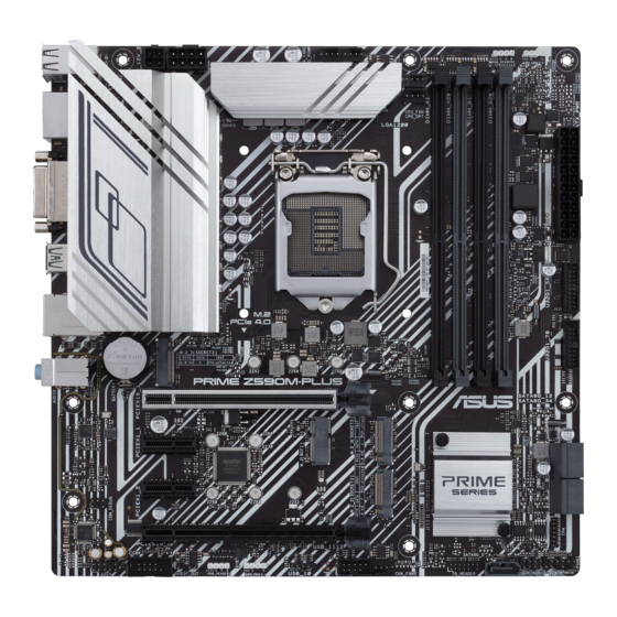
Page 14: Motherboard Layout
Motherboard layout 24.4cm(9.6in) RGB_HEADER2 ADD_GEN 2_2 USB_E1234 CHA_FAN1 AIO_PUMP ATX_12V_2 ATX_12V_1 CPU_FAN DIGI+ CPU_OPT 1442K HDMI_DP LGA1200 U32G2X2_C1 U32G2_9 LAN_U32G1_34 M.2_1(SOCKET3) BATTERY PCIE SATA IRST 4.0 X4 CPU-attached AUDIO 2242 2260 2280 PCIEX16_1 2230 Ethernet 2280 2260 PCIEX1_1 Super Intel ®... - Page 15 13. COM Port header 1-17 14. Front Panel Audio header 1-17 15. M.2 slot (Key E) 1-18 16. S/PDIF Out header 1-18 17. SPI TPM header (14-1pin) 1-19 18. System Panel header 1-20 19. Thunderbolt header 1-21 ™ PRIME Z590M-PLUS...
- Page 16 Contact your retailer immediately if the PnP cap is missing, or if you see any damage to the PnP cap/socket contacts/motherboard components. ASUS will shoulder the cost of repair only if the damage is shipment/ transit-related.
- Page 17 A DDR4 memory module is notched differently from a DDR, DDR2, or DDR3 module. DO NOT install a DDR, DDR2, or DDR3 memory module to the DDR4 slot. Recommended memory configurations DIMM_A1 DIMM_A2* DIMM_A2* DIMM_B1 DIMM_B2* DIMM_B2* DIMM_B2* PRIME Z590M-PLUS...
- Page 18 (D/C) from the same vendor. Check with the vendor to get the correct memory modules. • Visit the ASUS website for the latest QVL. Chapter 1: Product Introduction...
- Page 19 Please refer to the following tables for the recommended VGA configuration and Hyper M.2 configuration. Recommended VGA configuration Slot Slot Description Single VGA Dual VGA PCIEX16_1 PCIEX16_2 Connect a chassis fan to the chassis fan connectors when using multiple graphics cards for better thermal environment. PRIME Z590M-PLUS...
- Page 20 PCIe bifurcation & M.2 settings in PCIe x16 slot (from CPU) Slot Description Quantity of identifiable Intel M.2 SSD (pcs) PCIEX16_1 3 (x8+x4+x4) M.2_1 1 (x4) • Hyper M.2 X16 series card is sold separately. • M.2_1 is only supported with Intel 11th Core™...
- Page 21 Do not place jumper caps on the fan headers! • Ensure the cable is fully inserted into the header. Header Max. Current Max. Power Default Speed Shared Control CPU_FAN Q-Fan Controlled CPU_OPT Q-Fan Controlled CHA_FAN1 Q-Fan Controlled CHA_FAN2 Q-Fan Controlled AIO_PUMP Full-Speed PRIME Z590M-PLUS...
- Page 22 Power connectors These Power connectors allow you to connect your motherboard to a power supply. The power supply plugs are designed to fit in only one orientation. Find the proper orientation and push down firmly until the power supply plugs are fully inserted. ATX_12V_2 ATX_12V_1 PIN 1...
- Page 23 Optane™ Memory (Hybrid Storage device), it must be installed in PCH-attached slots with Intel Rapid Storage Technology. ® • When a device in SATA mode is installed on the M.2_2 socket, the SATA6G_1 port cannot be used. The M.2 SSD module is purchased separately. PRIME Z590M-PLUS 1-11...
- Page 24 When a device in SATA mode is installed on the M.2_2 socket, the SATA6G_1 port cannot be used. • Before creating a RAID set, refer to the RAID Configuration Guide. You can download the RAID Configuration Guide from the ASUS website. Chapter 1: Product Introduction 1-12...
- Page 25 2.0 ports. The USB 2.0 header provides data transfer speeds of up to 480 Mb/s connection speed. USB_10 PIN 1 USB1112 PIN 1 DO NOT connect a 1394 cable to the USB connectors. Doing so will damage the motherboard! The USB 2.0 module is purchased separately. PRIME Z590M-PLUS 1-13...
- Page 26 AURA Addressable Gen2 header The Addressable Gen2 header allows you to connect individually addressable RGB WS2812B LED strips or WS2812B based LED strips. ADD_GEN 2_2 ADD_GEN 2_1 The Addressable Gen2 header supports WS2812B addressable RGB LED strips (5V/ Data/Ground), with a maximum power rating of 3A (5V), and the addressable headers on this board can handle a combined maximum of 500 LEDs.
- Page 27 RGB LED strip is connected in the correct orientation, and the 12V connector is aligned with the 12V header on the motherboard. • The LED strip will only light up when the system is powered on. • The LED strip is purchased separately. PRIME Z590M-PLUS 1-15...
- Page 28 Clear CMOS header This header allows you to clear the Real Time Clock (RTC) RAM in CMOS. You can clear the CMOS memory of date, time, and system setup parameters by erasing the CMOS RTC RAM data. The onboard button cell battery powers the RAM data in CMOS, which include system setup information such as system passwords.
- Page 29 HD Audio. Connect one end of the front panel audio I/O module cable to this header. We recommend that you connect a high-definition front panel audio module to this connector to avail of the motherboard’s high-definition audio capability. PRIME Z590M-PLUS 1-17...
- Page 30 M.2 slot (Key E) The M.2(WIFI) slot allows you to install an M.2 Wi-Fi module (E-key, type 2230). M.2(WIFI) PIN2 PIN 1 S_USB_PP10_R S_USB_PN10_R X_WIFI_TXP X_WIFI_TXN CL_RST# CL_DATA X_WIFI_RXP CL_CLK X_WIFI_RXN C_PCIE_WIFI C_PCIE_WIFI# S_SUSCLK S_PLTRST# L1_WIFI_CLKREQ# BT_ISOLATE#_R S_WAKE# M2_ISOLATE#_R PIN74 PIN 75 The M.2 Wi-Fi module is purchased separately.
- Page 31 A TPM system also helps enhance network security, protects digital identities, and ensures platform integrity. PIN 1 VCCSPI S_SPI_TPM_IRQ# S_PLTRST# S_SPI_TPM_CS2# F2_SPI_CS1#_R F_BIOS_WP#_R +3V_SPI F_SPI_CS0#_R T_SPI_CLK T_SPI_MISO T_SPI_MOSI F_SPI_HOLD#_R The TPM module is purchased separately. PRIME Z590M-PLUS 1-19...
- Page 32 System Panel header The System Panel header supports several chassis-mounted functions. PLED PWRSW SPEAKER CHASSIS PANEL PIN 1 HDD_LED RESET PLED • System Power LED header (PLED) The 2-pin header allows you to connect the System Power LED. The System Power LED lights up when the system is connected to a power source, or when you turn on the system power, and blinks when the system is in sleep mode.
- Page 33 Thunderbolt™-enabled devices and DisplayPort-enabled devices to form a daisy chain-configuration. TB_HEADER PIN 1 • The add-on Thunderbolt™ I/O card and Thunderbolt™ cables are purchased separately. • Please visit the official website of your purchased Thunderbolt™ card for more details on compatibility. PRIME Z590M-PLUS 1-21...
- Page 34 Chapter 1: Product Introduction 1-22...
-
Page 35: Chapter 2: Basic Installation
NOT install a CPU designed for LGA1155, LGA1156, and LGA1151 sockets on the LGA1200 socket. • ASUS will not cover damages resulting from incorrect CPU installation/removal, incorrect CPU orientation/placement, or other damages resulting from negligence by the user. PRIME Z590M-PLUS... - Page 36 Chapter 2: Basic Installation...
-
Page 37: Cooling System Installation
2.1.2 Cooling system installation Apply Thermal Interface Material to the CPU cooling system and CPU before you install the cooling system, if necessary. To install a CPU heatsink and fan assembly PRIME Z590M-PLUS... - Page 38 To install an AIO cooler If you wish to install an AIO cooler, we recommend installing the AIO cooler after installing the motherboard into the chassis. AIO_PUMP CPU_FAN Chapter 2: Basic Installation...
-
Page 39: Dimm Installation
2.1.3 DIMM installation To remove a DIMM PRIME Z590M-PLUS... -
Page 40: Installation
2.1.4 M.2 installation To install an M.2 WIFI card Chapter 2: Basic Installation... - Page 41 To install an M.2 SSD card Supported M.2 type varies per motherboard. • The M.2 modules are purchased separately. • Use the screw and nut in the bundled 2-screw & 1-nut package when installing an M.2 SSD module into the M.2_3 socket. PRIME Z590M-PLUS...
-
Page 42: Motherboard Installation
2.1.5 Motherboard installation Install the ASUS I/O Shield to the chassis rear I/O panel. Some sharp edges and points might cause physical injury. We recommend you put on cut or puncture resistant gloves before motherboard and I/O shield installation. Place the motherboard into the chassis, ensuring that its rear I/O ports are aligned to the chassis’... - Page 43 Place eight (8) screws into the holes indicated by circles to secure the motherboard to the chassis. DO NOT over tighten the screws! Doing so can damage the motherboard. PRIME Z590M-PLUS...
-
Page 44: Atx Power Connection
2.1.6 ATX power connection Ensure to connect the 8-pin power plug. Chapter 2: Basic Installation 2-10... -
Page 45: Sata Device Connection
2.1.7 SATA device connection PRIME Z590M-PLUS 2-11... -
Page 46: Front I/O Connector
2.1.8 Front I/O connector To install the front panel connector To install USB 3.2 Gen 1 connector USB 3.2 Gen 1 To install front panel audio connector To install USB 2.0 connector AAFP USB 2.0 Chapter 2: Basic Installation 2-12... -
Page 47: Expansion Card Installation
2.1.9 Expansion card installation To install PCIe x16 cards To install PCIe x1 cards PRIME Z590M-PLUS 2-13... - Page 48 To install Thunderbolt™ series card 6-pin PCIe power connector USB Type-C ® port connects to Thunderbolt devices MiniDP in port connects to DP out port on the motherboard or a VGA card USB 2.0 header Thunderbolt™ header Ensure to install the Thunderbolt™ series card to a PCIe slot from PCH. •...
-
Page 49: Motherboard Rear And Audio Connections
Please connect your USB 3.2 Gen 1 devices to USB 3.2 Gen 1 ports and your USB 3.2 Gen 2 devices to USB 3.2 Gen 2 ports for faster and better performance for your devices. PRIME Z590M-PLUS 2-15... -
Page 50: Audio I/O Connections
* Intel I219-V 1Gb Ethernet port LED indications ® Activity Link LED Speed LED ACT/LINK SPEED Status Description Status Description No link 10 Mbps connection ORANGE Linked ORANGE 100 Mbps connection BLINKING Ethernet Data activity GREEN 1 Gbps connection port ** Audio 2, 4, 5.1, or 7.1-channel configuration Headset Port... - Page 51 Connect to Stereo Speakers Connect to 2-channel Speakers Connect to 4-channel Speakers PRIME Z590M-PLUS 2-17...
- Page 52 Connect to 5.1-channel Speakers Connect to 7.1-channel Speakers Chapter 2: Basic Installation 2-18...
-
Page 53: Starting Up For The First Time
While the system is ON, press the power button for less than four seconds to put the system on sleep mode or soft-off mode, depending on the BIOS setting. Press the power button for more than four seconds to let the system enter the soft-off mode regardless of the BIOS setting. PRIME Z590M-PLUS 2-19... - Page 54 Chapter 2: Basic Installation 2-20...
-
Page 55: Chapter 3: Bios And Raid Support
BIOS and RAID Support Knowing BIOS The new ASUS UEFI BIOS is a Unified Extensible Interface that complies with UEFI architecture, offering a user-friendly interface that goes beyond the traditional keyboard- only BIOS controls to enable a more flexible and convenient mouse input. You can easily navigate the new UEFI BIOS with the same smoothness as your operating system. -
Page 56: Bios Setup Program
BIOS setup program Use the BIOS Setup to update the BIOS or configure its parameters. The BIOS screen include navigation keys and brief onscreen help to guide you in using the BIOS Setup program. Entering BIOS at startup To enter BIOS Setup at startup, press <Delete> or <F2> during the Power-On Self Test (POST). -
Page 57: Asus Ez Flash 3
ASUS EZ Flash 3 The ASUS EZ Flash 3 feature allows you to update the BIOS without using an OS-based utility. Ensure to load the BIOS default settings to ensure system compatibility and stability. Select the Load Optimized Defaults item under the Exit menu or press hotkey <F5>. -
Page 58: Asus Crashfree Bios 3
ASUS CrashFree BIOS 3 The ASUS CrashFree BIOS 3 utility is an auto recovery tool that allows you to restore the BIOS file when it fails or gets corrupted during the updating process. You can restore a corrupted BIOS file using a USB flash drive that contains the BIOS file. -
Page 59: Raid Configurations
For more information on configuring your RAID sets, please refer to the RAID Configuration Guide which you can find at https://www.asus.com/support, or by scanning the QR code. RAID definitions RAID 0 (Data striping) optimizes two identical hard disk drives to read and write data in parallel, interleaved stacks. - Page 60 Chapter 3: BIOS Setup...
-
Page 61: Appendix
Appendix Notices FCC Compliance Information Responsible Party: Asus Computer International Address: 48720 Kato Rd., Fremont, CA 94538, USA Phone / Fax No: (510)739-3777 / (510)608-4555 This device complies with part 15 of the FCC Rules. Operation is subject to the following two conditions: (1) This device may not cause harmful interference, and (2) this device must accept any interference received, including interference that may cause undesired operation. - Page 62 Compliance Statement of Innovation, Science and Economic Development Canada (ISED) This device complies with Innovation, Science and Economic Development Canada licence exempt RSS standard(s). Operation is subject to the following two conditions: (1) this device may not cause interference, and (2) this device must accept any interference, including interference that may cause undesired operation of the device.
- Page 63 ASUS products sold in Vietnam, on or after September 23, 2011,meet the requirements of the Vietnam Circular 30/2011/TT-BCT. Các sản phẩm ASUS bán tại Việt Nam, vào ngày 23 tháng 9 năm2011 trở về sau, đều phải đáp ứng các yêu cầu của Thông tư 30/2011/TT-BCT của Việt Nam.
- Page 64 ASUS Recycling/Takeback Services ASUS recycling and takeback programs come from our commitment to the highest standards for protecting our environment. We believe in providing solutions for you to be able to responsibly recycle our products, batteries, other components as well as the packaging materials.
- Page 65 доступний на: www.asus.com/support Cijeli tekst EU izjave o sukladnosti dostupan je na: www.asus.com/support Türkçe AsusTek Computer Inc., bu aygıtın temel gereksinimlerle ve ilişkili Čeština Společnost ASUSTeK Computer Inc. tímto prohlašuje, že Yönergelerin diğer ilgili koşullarıyla uyumlu olduğunu beyan eder.
-
Page 66: Warranty
• ASUS offers a voluntary manufacturer’s Commercial Guarantee. • ASUS dragovoljno nudi komercijalno proizvođačko jamstvo. • ASUS reserves the right to interpret the provisions of the ASUS • ASUS zadržava prava na tumačenje odredbi ASUS komercijalnog Commercial Guarantee. jamstva. •... - Page 67 • Si tiene alguna queja o necesidad de un centro de reparación local Información de garantía de ASUS o el periodo de garantía del producto ASUS, por favor visite el sitio de Soporte de ASUS en https://www.asus.com/mx/support/ para • ASUS ofrece una garantía comercial voluntaria del fabricante.
-
Page 68: Asus Contact Information
+1-510-739-3777 +1-510-608-4555 Web site https://www.asus.com/us/ Technical Support Support fax +1-812-284-0883 Telephone +1-812-282-2787 Online support https://qr.asus.com/techserv ASUS COMPUTER GmbH (Germany and Austria) Address Harkortstrasse 21-23, 40880 Ratingen, Germany Web site https://www.asus.com/de Online contact https://www.asus.com/support/Product/ContactUs/Services/ questionform/?lang=de-de Technical Support Telephone (DE) +49-2102-5789557 Telephone (AT)