Table of Contents
Advertisement
Quick Links
IM10165
August 2013
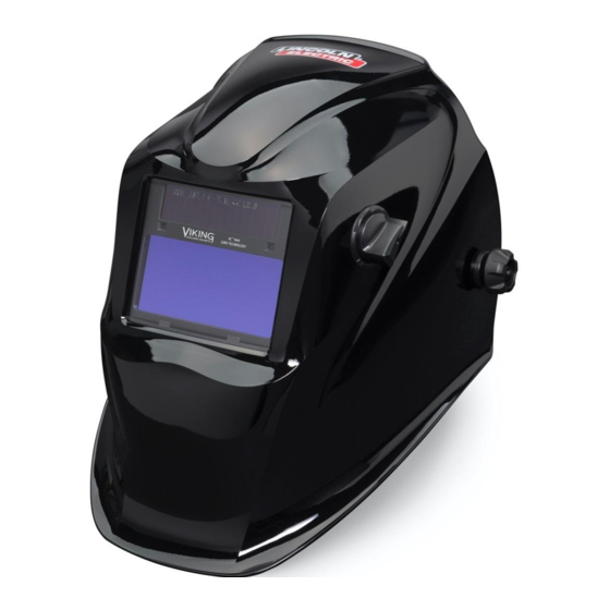
VIKING™ 1840 SERIES AUTO-DARKENING HELMETS
GRAPHICS MAY VARY
OPERATOR'S MANUAL
Copyright © Lincoln Global Inc.
• World's Leader in Welding and Cutting Products •
• Sales and Service through Subsidiaries and Distributors Worldwide •
Cleveland, Ohio 44117-1199 U.S.A. TEL: 216.481.8100 FAX: 216.486.1751 WEB SITE: www.lincolnelectric.com
Advertisement
Table of Contents

Related Manuals for Lincoln Electric VIKING 1840 Series


Summary of Contents for Lincoln Electric VIKING 1840 Series
- Page 1 IM10165 August 2013 VIKING™ 1840 SERIES AUTO-DARKENING HELMETS GRAPHICS MAY VARY OPERATOR’S MANUAL Copyright © Lincoln Global Inc. • World's Leader in Welding and Cutting Products • • Sales and Service through Subsidiaries and Distributors Worldwide • Cleveland, Ohio 44117-1199 U.S.A. TEL: 216.481.8100 FAX: 216.486.1751 WEB SITE: www.lincolnelectric.com...
-
Page 2: Table Of Contents
TABLE OF CONTENTS Page SAFETY WARNINGS – READ BEFORE USING HELMET INFORMATION SPECIFICATIONS OPERATING INSTRUCTIONS CARTRIDGE OPERATIONS/FEATURES SHADE GUIDE SETTINGS CARTRIDGE AND LENS REPLACEMENT TROUBLESHOOTING WARRANTY INFORMATION REPLACEMENT PARTS... -
Page 3: Safety Warnings - Read Before Using
SAFETY WARNINGS – READ BEFORE USING WARNING ARC Rays can injure eyes and burn skin • Before welding, always inspect helmet and filter lens to be sure they are fitted properly, in good condition and not damaged. • Check to see that the clear lens is clean and securely attached to the helmet. •... -
Page 4: Helmet Information
HELMET INFORMATION This Auto-Darkening Welding Helmet will automatically change from a light state (shade DIN4) to a dark state (shade DIN9-13) when arc welding starts. The filter automatically returns to a light state when the arc stops. Match your welding application to the shade indicated on the shade chart. (See Page 6) •... -
Page 5: Specifications
SPECIFICATIONS 1/1/1/1 Optical Class 96 x 47mm (3.78 x 1.85in.) LCD Viewing Area 110 x 90mm (4.33 x 3.54in.) Cartridge size Up to Shade DIN 16 at all times UV/IR Protection Arc Sensors DIN 4 Light State Shade DIN 9 to 13 and Grind Variable Welding Shades External knob - full adjustment Shade Control... -
Page 6: Operating Instructions
OPERATING INSTRUCTIONS Headgear Adjustment HEAD SIZE ADJUSTMENT: HEADGEAR TIGHTNESS is adjusted by push- ing in the Ratchet Knob and turning to adjust for the desired head size. This knob is located at the back of the helmet. HEADGEAR CROWN ADJUST- MENTS are made by adjusting for comfort and snapping the pins into the holes to lock securely in place. -
Page 7: Cartridge Operations/Features
CARTRIDGE OPERATION/FEATURES Variable Shade Control The shade can be adjusted from shade 9 to 13 based upon welding process or application (refer to Shade selection chart on page 6). The variable shade control knob is mounted on the exterior of the helmet shell. Grind mode can be selected by rotating the shade control knob counterclockwise till an audible click is heard. -
Page 8: Shade Guide Settings
HELMET CARE AND MAINTENANCE Cleaning: Clean helmet by wiping with a soft cloth. Clean cartridge surfaces regularly. Do not use strong cleaning solutions. Clean sensors and solar cells with soapy water solution and a clean cloth and wipe dry with a lint-free cloth. Do NOT submerge shade cartridge in water or other solution. -
Page 9: Cartridge And Lens Replacement
CARTRIDGE AND LENS REPLACEMENT Replacing Front Clear Cover Lens: Replace the front cover lens if it is dam- aged. Remove ADF holder assembly per Figure 1. Remove front cover lens from helmet assembly. Carefully remove gasket from cover lens. Install new cover lens into gasket and assemble to helmet shell. -
Page 10: Troubleshooting
TROUBLESHOOTING GUIDE Test your shade cartridge prior to welding by directing the front of the cartridge toward a bright source of light. Then, using your fingers, rapidly cover and uncov- er the sensors. The cartridge should darken momentarily as the sensor is exposed. -
Page 11: Warranty Information
WARRANTY INFORMATION WARRANTY INFORMATION: Reference IMWS1 included in Literature. SPATTER DAMAGE IS NOT COVERED BY WARRANTY: Do not use this product without the correct protective clear lenses installed properly on both sides of the Auto-Darkening Filter cartridge (ADF). The clear lenses supplied with this helmet are properly sized to work with this product and substitutions from other suppliers should be avoided. - Page 12 • World's Leader in Welding and Cutting Products • • Sales and Service through Subsidiaries and Distributors Worldwide • Cleveland, Ohio 44117-1199 U.S.A. TEL: 216.481.8100 FAX: 216.486.1751 WEB SITE: www.lincolnelectric.com...