Table of Contents
Advertisement
Quick Links
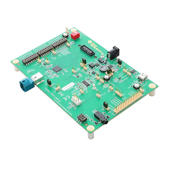
The DS90Ux941AS-Q1EVM (Evaluation Module) converts DSI to FPD-Link III. This kit will demonstrate
the functionality and operation of the DS90Ux941AS-Q1. The DS90Ux941AS-Q1 is a DSI to FPD-Link III
Serializer which, in conjunction with the DS90Ux940-Q1/DS90Ux948-Q1 Deserializers, takes the data
from a DSI serial stream and translates it into either single- or dual-lane FPD-Link III interface. The
DS90Ux941AS-Q1 serializes a MIPI DSI input supporting video resolutions up to 2K, WUXGA and
1080p60 with 24-bit color depth.
1
.......................................................................................................................
2
3
4
5
6
7
8
9
10
11
12
13
14
15
1
Applications Diagram
2
Typical Configuration
3
4
5
6
7
8
9
10
11
12
13
14
15
.................................................................................................................
16
17
SNLU241A - December 2018 - Revised April 2019
Submit Documentation Feedback
DS90Ux941AS-Q1EVM User's Guide
.........................................................................................................
.......................................................................................................
.....................................................................................
........................................................................................................
........................................................................................................
............................................................................................................
....................................................................................................
.....................................................................................................
..................................................................................................
.......................................................................................................
...........................................................................................
................................................................................
....................................................................................................
..........................................................................................................
............................................................................................
.......................................................................................................
........................................................................................................
........................................................................................................
......................................................................................................
.............................................................................................................
..........................................................................................................
..........................................................................................................
.......................................................................................................
...............................................................................................
.........................................................................................................
...................................................................................................
.................................................................................................
..........................................................................................................
...........................................................................................................
..................................................................................................
.........................................................................................................
.....................................................................................................
Copyright © 2018-2019, Texas Instruments Incorporated
SNLU241A - December 2018 - Revised April 2019
Contents
List of Figures
User's Guide
3
3
4
4
4
4
5
6
6
6
10
19
23
24
24
29
36
4
4
5
11
11
12
13
14
15
16
17
18
19
19
20
20
21
1
Advertisement
Table of Contents

Related Manuals for Texas Instruments DS90Ux941AS-Q1EVM


Summary of Contents for Texas Instruments DS90Ux941AS-Q1EVM
-
Page 1: Table Of Contents
SNLU241A – December 2018 – Revised April 2019 DS90Ux941AS-Q1EVM User's Guide The DS90Ux941AS-Q1EVM (Evaluation Module) converts DSI to FPD-Link III. This kit will demonstrate the functionality and operation of the DS90Ux941AS-Q1. The DS90Ux941AS-Q1 is a DSI to FPD-Link III Serializer which, in conjunction with the DS90Ux940-Q1/DS90Ux948-Q1 Deserializers, takes the data from a DSI serial stream and translates it into either single- or dual-lane FPD-Link III interface. - Page 2 Configuration Select (MODE_SEL1) - SW-DIP8 - S6 ......................IDx SW-DIP8 - S3 ......................Bill of Materials Trademarks All trademarks are the property of their respective owners. DS90Ux941AS-Q1EVM User's Guide SNLU241A – December 2018 – Revised April 2019 Submit Documentation Feedback Copyright © 2018–2019, Texas Instruments Incorporated...
-
Page 3: General Description
General Description The DS90Ux941AS-Q1EVM (Evaluation Module) converts DSI to FPD-Link III. This kit will demonstrate the functionality and operation of the DS90Ux941AS-Q1. The DS90Ux941AS-Q1 is a DSI to FPD-Link III Serializer which, in conjunction with the DS90Ux940-Q1/DS90Ux948-Q1 Deserializers, takes the data from a DSI serial stream and translates it into either single- or dual-lane FPD-Link III interface. -
Page 4: System Requirements
Deserializer (I2C) Figure 2. Typical Configuration Figure 1 Figure 2 show the use of the chipset in a display application. DS90Ux941AS-Q1EVM User's Guide SNLU241A – December 2018 – Revised April 2019 Submit Documentation Feedback Copyright © 2018–2019, Texas Instruments Incorporated... -
Page 5: Quick Start Guide
For details of pin names and pin functions, refer to the DS90Ux941AS-Q1 data sheets. Figure 3. Interfacing to the EVM SNLU241A – December 2018 – Revised April 2019 DS90Ux941AS-Q1EVM User's Guide Submit Documentation Feedback Copyright © 2018–2019, Texas Instruments Incorporated... -
Page 6: Default Jumper Settings
Table 4. FPD-Link III Output Signals P1 DESIGNATOR PORT SIGNAL P1.1 DOUT0- FPD-Link III Port 0 P1.3 DOUT0+ P1.2 DOUT1- FPD-Link III Port 1 P1.4 DOUT1+ DS90Ux941AS-Q1EVM User's Guide SNLU241A – December 2018 – Revised April 2019 Submit Documentation Feedback Copyright © 2018–2019, Texas Instruments Incorporated... -
Page 7: Dsi Input Signals
Master I2S Word Clock Input / Remote or Local I/O J12.22 SCLK Master I2S Clock Input J12.24 MCLK Master Mode I2S System Clock SNLU241A – December 2018 – Revised April 2019 DS90Ux941AS-Q1EVM User's Guide Submit Documentation Feedback Copyright © 2018–2019, Texas Instruments Incorporated... -
Page 8: Spi/D_Gpio Interface
0.790 × 0.825 × 1.421 18.7 71.5 (VDD18) (VDD18) (VDD18) 0.880 × (VDD18) OPEN (VDD18) (VDD18) Only set one high DS90Ux941AS-Q1EVM User's Guide SNLU241A – December 2018 – Revised April 2019 Submit Documentation Feedback Copyright © 2018–2019, Texas Instruments Incorporated... -
Page 9: Configuration Select (Mode_Sel1) - Sw-Dip8 - S6
0x20 S3.4 0x12 0x24 S3.5 0x14 0x28 S3.6 0x16 0x2C S3.7 0x18 0x30 S3.8 0x1A 0x34 Only set one high. SNLU241A – December 2018 – Revised April 2019 DS90Ux941AS-Q1EVM User's Guide Submit Documentation Feedback Copyright © 2018–2019, Texas Instruments Incorporated... -
Page 10: Alp Software Setup
1. Download the ALP-PROFILE-UPDATE, snlc062.zip, from the TI Analog LaunchPAD page: http://www.ti.com/tool/alp. 2. Extract the files and run the executable file ALP_PROFILE_UPDATE_v02_setup_v_x_x_x.exe. The profile will be installed to the profile folder found at: C:\Program Files (x64)\Texas Instruments\Analog LaunchPAD vx.x.x\Profiles\. DS90Ux941AS-Q1EVM User's Guide SNLU241A –... -
Page 11: Launching Alp
Make sure all the software has been installed and the hardware is powered on and connected to the PC. Execute “Analog LaunchPAD” shortcut from the start menu. The default start menu location is under All Programs > Texas Instruments > Analog LaunchPAD vx.x.x > Analog LaunchPAD to start MainGUI.exe. Figure 4. Launching ALP The application should come up in the state shown in the figure below. -
Page 12: Follow-Up Screen
ALP Software Setup www.ti.com After selecting the DS90Ux941AS-Q1, the screen shown in Figure 6 should appear. Figure 6. Follow-Up Screen DS90Ux941AS-Q1EVM User's Guide SNLU241A – December 2018 – Revised April 2019 Submit Documentation Feedback Copyright © 2018–2019, Texas Instruments Incorporated... -
Page 13: Alp Information Tab
The Information tab is shown in Figure 7. Note that the device revision could be different. Figure 7. ALP Information Tab SNLU241A – December 2018 – Revised April 2019 DS90Ux941AS-Q1EVM User's Guide Submit Documentation Feedback Copyright © 2018–2019, Texas Instruments Incorporated... -
Page 14: Alp Pattern Generator Tab
11.7 Pattern Generator Tab The SER Pattern Generator tab is shown in Figure Figure 8. ALP Pattern Generator Tab DS90Ux941AS-Q1EVM User's Guide SNLU241A – December 2018 – Revised April 2019 Submit Documentation Feedback Copyright © 2018–2019, Texas Instruments Incorporated... -
Page 15: Alp Registers Tab
ALP Software Setup www.ti.com 11.8 Registers Tab The Register tab is shown in Figure Figure 9. ALP Registers Tab SNLU241A – December 2018 – Revised April 2019 DS90Ux941AS-Q1EVM User's Guide Submit Documentation Feedback Copyright © 2018–2019, Texas Instruments Incorporated... -
Page 16: Alp Device Id Selected
Address 0x00 selected. Note that the “Value:” box ( ) will now show the hex value of that register. Figure 10. ALP Device ID Selected DS90Ux941AS-Q1EVM User's Guide SNLU241A – December 2018 – Revised April 2019 Submit Documentation Feedback Copyright © 2018–2019, Texas Instruments Incorporated... -
Page 17: Alp Device Id Expanded
“0” or W. Click the “Apply” button to write to the register, and “refresh” to see the new value of the selected (highlighted) register. The box toggles on every mouse click. SNLU241A – December 2018 – Revised April 2019 DS90Ux941AS-Q1EVM User's Guide Submit Documentation Feedback Copyright © 2018–2019, Texas Instruments Incorporated... -
Page 18: Alp Scripting Tab
ALP Framework application. DS90Ux941AS-Q1EVM User's Guide SNLU241A – December 2018 – Revised April 2019 Submit Documentation Feedback Copyright © 2018–2019, Texas Instruments Incorporated... -
Page 19: Troubleshooting Alp Software
Figure 14. Remove Incorrect Profile Find the correct profile under the Select a Daughter Board list, highlight the profile and press Add. SNLU241A – December 2018 – Revised April 2019 DS90Ux941AS-Q1EVM User's Guide Submit Documentation Feedback Copyright © 2018–2019, Texas Instruments Incorporated... -
Page 20: Add Correct Profile
Figure 15. Add Correct Profile Select Ok and the correct profile should now be loaded. Figure 16. Finish Setup DS90Ux941AS-Q1EVM User's Guide SNLU241A – December 2018 – Revised April 2019 Submit Documentation Feedback Copyright © 2018–2019, Texas Instruments Incorporated... -
Page 21: Alp No Devices Error
When the ALP is operating in demo mode there is a “(Demo Mode)” indication in the lower left of the application status bar as shown in Figure SNLU241A – December 2018 – Revised April 2019 DS90Ux941AS-Q1EVM User's Guide Submit Documentation Feedback Copyright © 2018–2019, Texas Instruments Incorporated... -
Page 22: Alp In Demo Mode
After demo mode is disabled, the ALP software will poll the ALP hardware. The ALP software will update and have only “DS90Ux941AS-Q1” under the “Devices” drop-down menu. DS90Ux941AS-Q1EVM User's Guide SNLU241A – December 2018 – Revised April 2019 Submit Documentation Feedback Copyright © 2018–2019, Texas Instruments Incorporated... -
Page 23: Typical Connection And Test Equipment
Figure 22 shows a typical test setup using a video generator and logic analyzer. Figure 22. Typical Test Setup for Evaluation SNLU241A – December 2018 – Revised April 2019 DS90Ux941AS-Q1EVM User's Guide Submit Documentation Feedback Copyright © 2018–2019, Texas Instruments Incorporated... -
Page 24: Equipment References
24 AWG (or larger diameter) cable for high-speed data applications. Leoni Dacar 538 series cable: www.leoni-automotive-cables.com Rosenberger HSD connector: www.rosenberger.de/en/Products/35_Automotive_HSD.php DS90Ux941AS-Q1EVM User's Guide SNLU241A – December 2018 – Revised April 2019 Submit Documentation Feedback Copyright © 2018–2019, Texas Instruments Incorporated... -
Page 25: Bill Of Materials
LED, Green, SMD Lite-On LTST-C190GKT Diode, Schottky, 40 V, 1 A, SOD-123 Diodes Inc. 1N5819HW-7-F D3, D4 LED, Orange, SMD Lite-On LTST-C190KFKT SNLU241A – December 2018 – Revised April 2019 Bill of Materials Submit Documentation Feedback Copyright © 2018–2019, Texas Instruments Incorporated... - Page 26 RES, 33, 5%, 0.063 W, AEC-Q200 Grade 0, Vishay-Dale CRCW040233R0JNED 0402 R82, R87, R88 RES, 1.5 k, 5%, 0.063 W, AEC-Q200 Grade 0, Vishay-Dale CRCW04021K50JNED 0402 Bill of Materials SNLU241A – December 2018 – Revised April 2019 Submit Documentation Feedback Copyright © 2018–2019, Texas Instruments Incorporated...
- Page 27 Texas Instruments TPS767D318PWP 2.7 to 10 V Input, 28-pin HTSSOP (PWP), -40 to 125 degC, Green (RoHS and no Sb/Br) SNLU241A – December 2018 – Revised April 2019 Bill of Materials Submit Documentation Feedback Copyright © 2018–2019, Texas Instruments Incorporated...
- Page 28 RTD0064F (VQFNP-64) DS90UB941ASRTDRQ1 OSC, 12.288 MHz, 3.3 Vdc, SMD ECS Inc. ECS-8FA3X-122.8-TR Crystal, 24.000 MHz, 20pF, SMD ECS Inc. ECS-240-20-5PX-TR Bill of Materials SNLU241A – December 2018 – Revised April 2019 Submit Documentation Feedback Copyright © 2018–2019, Texas Instruments Incorporated...
-
Page 29: Appendix Aevm Pcb Schematics
DS90UX941AS-Q1 FPD3 USB-2-ANY EXT UC MODE_SEL SPI/D_GPIO GPIO INTB 3.3V Power Power 1.8V Audio 1.1V Figure 23. Top Level Schematic SNLU241A – December 2018 – Revised April 2019 EVM PCB Schematics Submit Documentation Feedback Copyright © 2018–2019, Texas Instruments Incorporated... -
Page 30: Main Schematic
I2S_CLK/GPIO8_REG I2S_CLK/GPIO8_REG R136 R137 I2S_DA/GPIO6_REG I2S_DA/GPIO6_REG R138 I2S_DB/GPIO5_REG I2S_DB/GPIO5_REG R139 I2S_DC/GPIO2 I2S_DC/GPIO2 R140 I2S_DD/GPIO3 I2S_DD/GPIO3 DS90UH941ASRTDRQ1 Figure 24. Main Schematic EVM PCB Schematics SNLU241A – December 2018 – Revised April 2019 Submit Documentation Feedback Copyright © 2018–2019, Texas Instruments Incorporated... -
Page 31: Configuration Schematic
64.9k 10.0k 10.0k INTB B3F-1000 PDB / INTB Switches Mode Select 1 (MODE_SEL1) 10µF MODE_SEL1 0.1uF Figure 25. Configuration Schematic SNLU241A – December 2018 – Revised April 2019 EVM PCB Schematics Submit Documentation Feedback Copyright © 2018–2019, Texas Instruments Incorporated... -
Page 32: Schematic Connectors
GPIO4/SPI(SIMO)/UART(TXD) D_GPIO0/MOSI MCLK GPIO5/SPI(SOMI)/UART(RXD) D_GPIO1/MISO D_GPIO0/MOSI GPIO2/SPI(SCLK) D_GPIO2/SPLK D_GPIO1/MISO GPIO6/PWM1/SPI(CS) D_GPIO3/SS D_GPIO2/SPLK D_GPIO3/SS DAOUT LRCK SCKIN Figure 26. Schematic Connectors EVM PCB Schematics SNLU241A – December 2018 – Revised April 2019 Submit Documentation Feedback Copyright © 2018–2019, Texas Instruments Incorporated... -
Page 33: Power Schematic
100k 1RESET R111 100k 2RESET VDD1 R112 1GND R113 2GND VDD33 R114 TP10 TPS767D318PWP 0.1uF 10µF Figure 27. Power Schematic SNLU241A – December 2018 – Revised April 2019 EVM PCB Schematics Submit Documentation Feedback Copyright © 2018–2019, Texas Instruments Incorporated... -
Page 34: Audio Schematic
DOUT 10µF 10µF 0.1uF LRCK PCM1808PWR VDD33 DAOUT OUTPUT 10µF 0.1uF TRI-STATE LRCK 10.0k SCKIN SH-J1 Figure 28. Audio Schematic EVM PCB Schematics SNLU241A – December 2018 – Revised April 2019 Submit Documentation Feedback Copyright © 2018–2019, Texas Instruments Incorporated... -
Page 35: Usb2Any Schematic
AVSS1 VDD33_UC VDD33 AVCC1 AVSS2 330 ohm DVCC1 DVSS1 DVCC2 DVSS2 MSP430F5529IPN 0.1uF 10µF 0.1uF 0.1uF Figure 29. USB2Any Schematic SNLU241A – December 2018 – Revised April 2019 EVM PCB Schematics Submit Documentation Feedback Copyright © 2018–2019, Texas Instruments Incorporated... -
Page 36: Appendix B Board Layout
Appendix B SNLU241A – December 2018 – Revised April 2019 Board Layout Figure 30. Top Overlay Board Layout SNLU241A – December 2018 – Revised April 2019 Submit Documentation Feedback Copyright © 2018–2019, Texas Instruments Incorporated... -
Page 37: Top Solder
Appendix B www.ti.com Figure 31. Top Solder SNLU241A – December 2018 – Revised April 2019 Board Layout Submit Documentation Feedback Copyright © 2018–2019, Texas Instruments Incorporated... -
Page 38: Layer1 Top
Appendix B www.ti.com Figure 32. Layer1 Top Board Layout SNLU241A – December 2018 – Revised April 2019 Submit Documentation Feedback Copyright © 2018–2019, Texas Instruments Incorporated... -
Page 39: Layer 6 Bottom
Appendix B www.ti.com Figure 33. Layer 6 Bottom SNLU241A – December 2018 – Revised April 2019 Board Layout Submit Documentation Feedback Copyright © 2018–2019, Texas Instruments Incorporated... -
Page 40: Layer6 Solder Bottom
Appendix B www.ti.com Figure 34. Layer6 Solder Bottom Board Layout SNLU241A – December 2018 – Revised April 2019 Submit Documentation Feedback Copyright © 2018–2019, Texas Instruments Incorporated... -
Page 41: Layer6 Bottom Overlay
Appendix B www.ti.com Figure 35. Layer6 Bottom Overlay SNLU241A – December 2018 – Revised April 2019 Board Layout Submit Documentation Feedback Copyright © 2018–2019, Texas Instruments Incorporated... -
Page 42: Drill Drawing
Appendix B www.ti.com Figure 36. Drill Drawing Board Layout SNLU241A – December 2018 – Revised April 2019 Submit Documentation Feedback Copyright © 2018–2019, Texas Instruments Incorporated... -
Page 43: Board Dimensions
Appendix B www.ti.com Figure 37. Board Dimensions SNLU241A – December 2018 – Revised April 2019 Board Layout Submit Documentation Feedback Copyright © 2018–2019, Texas Instruments Incorporated... - Page 44 Changed Typical Connection and Test Equipment Images ....................... • Changed Bill of Materials ..................• Changed schematics, layouts and board shots Revision History SNLU241A – December 2018 – Revised April 2019 Submit Documentation Feedback Copyright © 2018–2019, Texas Instruments Incorporated...
- Page 45 STANDARD TERMS FOR EVALUATION MODULES Delivery: TI delivers TI evaluation boards, kits, or modules, including any accompanying demonstration software, components, and/or documentation which may be provided together or separately (collectively, an “EVM” or “EVMs”) to the User (“User”) in accordance with the terms set forth herein.
- Page 46 www.ti.com Regulatory Notices: 3.1 United States 3.1.1 Notice applicable to EVMs not FCC-Approved: FCC NOTICE: This kit is designed to allow product developers to evaluate electronic components, circuitry, or software associated with the kit to determine whether to incorporate such items in a finished product and software developers to write software applications for use with the end product.
- Page 47 www.ti.com Concernant les EVMs avec antennes détachables Conformément à la réglementation d'Industrie Canada, le présent émetteur radio peut fonctionner avec une antenne d'un type et d'un gain maximal (ou inférieur) approuvé pour l'émetteur par Industrie Canada. Dans le but de réduire les risques de brouillage radioélectrique à...
- Page 48 www.ti.com EVM Use Restrictions and Warnings: 4.1 EVMS ARE NOT FOR USE IN FUNCTIONAL SAFETY AND/OR SAFETY CRITICAL EVALUATIONS, INCLUDING BUT NOT LIMITED TO EVALUATIONS OF LIFE SUPPORT APPLICATIONS. 4.2 User must read and apply the user guide and other available documentation provided by TI regarding the EVM prior to handling or using the EVM, including without limitation any warning or restriction notices.
- Page 49 Notwithstanding the foregoing, any judgment may be enforced in any United States or foreign court, and TI may seek injunctive relief in any United States or foreign court. Mailing Address: Texas Instruments, Post Office Box 655303, Dallas, Texas 75265 Copyright © 2019, Texas Instruments Incorporated...
- Page 50 TI products. TI’s provision of these resources does not expand or otherwise alter TI’s applicable warranties or warranty disclaimers for TI products. Mailing Address: Texas Instruments, Post Office Box 655303, Dallas, Texas 75265 Copyright © 2019, Texas Instruments Incorporated...