Table of Contents
Advertisement
Quick Links
MSP430FR4133 LaunchPad™ Development Kit
The
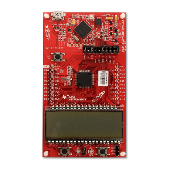
MSP-EXP430FR4133
the
MSP430FR4133
the MSP430™ ultra-low-power (ULP) FRAM-based microcontroller (MCU) platform, including on-board
emulation for programming, debugging, and energy measurements. The board features on-board buttons
and LEDs for quick integration of a simple user interface and a liquid crystal display (LCD) that showcases
the integrated driver with flexible software-configurable pins.
SLAU595B – October 2014 – Revised January 2017
Submit Documentation Feedback
LaunchPad™ Development Kit is an easy-to-use evaluation module (EVM) for
microcontroller (see
Figure
Figure 1. MSP-EXP430FR4133
MSP430FR4133 LaunchPad™ Development Kit (MSP ‑ EXP430FR4133)
Copyright © 2014–2017, Texas Instruments Incorporated
SLAU595B – October 2014 – Revised January 2017
(MSP ‑ ‑ EXP430FR4133)
1). It contains everything needed to start developing on
User's Guide
1
Advertisement
Table of Contents

Related Manuals for Texas Instruments LaunchPad MSP430FR4133


Summary of Contents for Texas Instruments LaunchPad MSP430FR4133
- Page 1 LEDs for quick integration of a simple user interface and a liquid crystal display (LCD) that showcases the integrated driver with flexible software-configurable pins. Figure 1. MSP-EXP430FR4133 MSP430FR4133 LaunchPad™ Development Kit (MSP ‑ EXP430FR4133) SLAU595B – October 2014 – Revised January 2017 Submit Documentation Feedback Copyright © 2014–2017, Texas Instruments Incorporated...
-
Page 2: Table Of Contents
IDE Minimum Requirements for MSP-EXP430FR4133 ..................List of Source Files and Folders ..............How MSP430 Device Documentation is Organized MSP430FR4133 LaunchPad™ Development Kit (MSP ‑ EXP430FR4133) SLAU595B – October 2014 – Revised January 2017 Submit Documentation Feedback Copyright © 2014–2017, Texas Instruments Incorporated... -
Page 3: Getting Started
An easy way to get familiar with the EVM is by using its preprogrammed out-of-box code. It demonstrates some key features from a user level. MSP430FR4133 LaunchPad™ Development Kit (MSP ‑ EXP430FR4133) SLAU595B – October 2014 – Revised January 2017 Submit Documentation Feedback Copyright © 2014–2017, Texas Instruments Incorporated... - Page 4 EVM and a PC through the provided USB cable is all that is needed. MSP430FR4133 LaunchPad™ Development Kit (MSP ‑ EXP430FR4133) SLAU595B – October 2014 – Revised January 2017 Submit Documentation Feedback Copyright © 2014–2017, Texas Instruments Incorporated...
-
Page 5: Msp-Exp430Fr4133 Overview
- 6 symbols for various applications - Ultra-lo w power display Button/Switch Button/Switch User LEDs LED1, LED2 Figure 2. MSP-EXP430FR4133 Overview MSP430FR4133 LaunchPad™ Development Kit (MSP ‑ EXP430FR4133) SLAU595B – October 2014 – Revised January 2017 Submit Documentation Feedback Copyright © 2014–2017, Texas Instruments Incorporated... -
Page 6: Block Diagram
Two timer blocks and up to three serial interfaces (SPI, UART, or I • Analog: 10-channel 10-bit differential ADC • Digital: RTC, CRC MSP430FR4133 LaunchPad™ Development Kit (MSP ‑ EXP430FR4133) SLAU595B – October 2014 – Revised January 2017 Submit Documentation Feedback Copyright © 2014–2017, Texas Instruments Incorporated... -
Page 7: Hardware
TEST/SBWTCK P2.2/L26 P4.0/TA1.1 P2.3/L27 P8.3/TA1.2 P2.4/L28 P8.2/TA1CLK P2.5/L29 P8.1/ACLK/A9 P2.6/L30 P8.0/SMCLK/A8 P2.7/L31 Figure 4. MSP430FR4133 Pinout MSP430FR4133 LaunchPad™ Development Kit (MSP ‑ EXP430FR4133) SLAU595B – October 2014 – Revised January 2017 Submit Documentation Feedback Copyright © 2014–2017, Texas Instruments Incorporated... -
Page 8: Energytrace Technology
Files. The software and more information about the debugger can be found on the eZ-FET lite wiki. MSP430FR4133 LaunchPad™ Development Kit (MSP ‑ EXP430FR4133) SLAU595B – October 2014 – Revised January 2017 Submit Documentation Feedback Copyright © 2014–2017, Texas Instruments Incorporated... -
Page 9: Isolation Block Connections
Spy-Bi-Wire emulation: SBWTDIO data signal. This pin also functions as the RST signal (active low). SBW TST Spy-Bi-Wire emulation: SBWTCK clock signal. This pin also functions as the TST signal. MSP430FR4133 LaunchPad™ Development Kit (MSP ‑ EXP430FR4133) SLAU595B – October 2014 – Revised January 2017 Submit Documentation Feedback Copyright © 2014–2017, Texas Instruments Incorporated... -
Page 10: Ez-Fet Emulator
You need to identify the COM port for the backchannel. On Windows PCs, Device Manager can assist (see Figure Figure 7. Application Backchannel UART in Device Manager MSP430FR4133 LaunchPad™ Development Kit (MSP ‑ EXP430FR4133) SLAU595B – October 2014 – Revised January 2017 Submit Documentation Feedback Copyright © 2014–2017, Texas Instruments Incorporated... -
Page 11: Lcd Segment Layout
8). This LCD is driven by the internal LCD driver on the MSP430FR4133 device. Figure 8. LCD Segment Layout MSP430FR4133 LaunchPad™ Development Kit (MSP ‑ EXP430FR4133) SLAU595B – October 2014 – Revised January 2017 Submit Documentation Feedback Copyright © 2014–2017, Texas Instruments Incorporated... -
Page 12: Lcd Fh-1138P Segment Mapping
COM3 COM2 COM1 COM0 A1DP A2COL A2DP A3DP A4COL A4DP A5DP COM3 COM2 COM1 COM0 BATT MSP430FR4133 LaunchPad™ Development Kit (MSP ‑ EXP430FR4133) SLAU595B – October 2014 – Revised January 2017 Submit Documentation Feedback Copyright © 2014–2017, Texas Instruments Incorporated... -
Page 13: Lcd To Msp430 Connections
P7.7 P7.6 A5DP LCDM2 P7.5 P7.4 LCDM1 P7.3 COM3 P7.2 COM2 LCDM0 P7.1 COM1 P7.0 COM0 MSP430FR4133 LaunchPad™ Development Kit (MSP ‑ EXP430FR4133) SLAU595B – October 2014 – Revised January 2017 Submit Documentation Feedback Copyright © 2014–2017, Texas Instruments Incorporated... -
Page 14: Msp-Exp430Fr4133
1.8 V to 3.6 V. More information can be found in the MSP430FR4133 data sheet (SLAS865). MSP430FR4133 LaunchPad™ Development Kit (MSP ‑ EXP430FR4133) SLAU595B – October 2014 – Revised January 2017 Submit Documentation Feedback Copyright © 2014–2017, Texas Instruments Incorporated... - Page 15 This wiring can be done either with jumper wires or by designing the board with a connector that plugs into the isolation jumper block. MSP430FR4133 LaunchPad™ Development Kit (MSP ‑ EXP430FR4133) SLAU595B – October 2014 – Revised January 2017 Submit Documentation Feedback Copyright © 2014–2017, Texas Instruments Incorporated...
-
Page 16: Launchpad To Boosterpack Connector Pinout
SPI CS Other MCLK GPIO P1.4 TA0CLK GPIO P1.5 Figure 10. LaunchPad to BoosterPack Connector Pinout MSP430FR4133 LaunchPad™ Development Kit (MSP ‑ EXP430FR4133) SLAU595B – October 2014 – Revised January 2017 Submit Documentation Feedback Copyright © 2014–2017, Texas Instruments Incorporated... -
Page 17: Hardware Change Log
To quickly program a demo onto the LaunchPad, simply navigate into the corresponding demo project's directory and double click the "Program <Example>.bat" file. MSP430FR4133 LaunchPad™ Development Kit (MSP ‑ EXP430FR4133) SLAU595B – October 2014 – Revised January 2017 Submit Documentation Feedback Copyright © 2014–2017, Texas Instruments Incorporated... -
Page 18: Programming The Launchpad With Program Batch Files
Code Composer Studio™ IDE IAR Embedded Workbench™ IDE CCS v6.0 or later IAR EW430 v6.10 or later MSP430FR4133 LaunchPad™ Development Kit (MSP ‑ EXP430FR4133) SLAU595B – October 2014 – Revised January 2017 Submit Documentation Feedback Copyright © 2014–2017, Texas Instruments Incorporated... -
Page 19: Directing The Project>Import Function To The Demo Project
"Discovered projects" and is checked (see Figure 13). MSP430FR4133 LaunchPad™ Development Kit (MSP ‑ EXP430FR4133) SLAU595B – October 2014 – Revised January 2017 Submit Documentation Feedback Copyright © 2014–2017, Texas Instruments Incorporated... -
Page 20: When Ccs Has Found The Project
LCD_E module (active in low power mode 3.5), combined with the RTC counter, ADC, and internal temperature sensor, to implement simple stopwatch and thermometer. MSP430FR4133 LaunchPad™ Development Kit (MSP ‑ EXP430FR4133) SLAU595B – October 2014 – Revised January 2017 Submit Documentation Feedback Copyright © 2014–2017, Texas Instruments Incorporated... -
Page 21: List Of Source Files And Folders
MSP430FR4133 enters LPM3.5 with the LCD remaining on displaying the last measured temperature. MSP430FR4133 LaunchPad™ Development Kit (MSP ‑ EXP430FR4133) SLAU595B – October 2014 – Revised January 2017 Submit Documentation Feedback Copyright © 2014–2017, Texas Instruments Incorporated... -
Page 22: Additional Resources
MSP430Ware is built into the TI Resource Explorer, for easily browsing tools. For example, all of the software examples are shown in Figure MSP430FR4133 LaunchPad™ Development Kit (MSP ‑ EXP430FR4133) SLAU595B – October 2014 – Revised January 2017 Submit Documentation Feedback Copyright © 2014–2017, Texas Instruments Incorporated... -
Page 23: Msp-Exp430Fr4133 Software Examples In Ti Resource Explorer
Search the forums at e2e.ti.com. If you cannot find your answer, post your question to the community. MSP430FR4133 LaunchPad™ Development Kit (MSP ‑ EXP430FR4133) SLAU595B – October 2014 – Revised January 2017 Submit Documentation Feedback Copyright © 2014–2017, Texas Instruments Incorporated... - Page 24 It also allows more flexibility in stacking BoosterPacks and other LaunchPads. MSP430FR4133 LaunchPad™ Development Kit (MSP ‑ EXP430FR4133) SLAU595B – October 2014 – Revised January 2017 Submit Documentation Feedback Copyright © 2014–2017, Texas Instruments Incorporated...
-
Page 25: Schematics
Sheet 4,5,6 Sheet 2 Sheet 2 Texas Instruments Mike Stein Copyright © 2017, Texas Instruments Incorporated Figure 15. Schematics (1 of 6) SLAU595B – October 2014 – Revised January 2017 MSP430FR4133 LaunchPad™ Development Kit (MSP ‑ EXP430FR4133) Submit Documentation Feedback... -
Page 26: Schematics (2 Of 6)
P2.7/L31 100n MSP430FR4x Texas Instruments Mike Stein Copyright © 2017, Texas Instruments Incorporated Figure 16. Schematics (2 of 6) MSP430FR4133 LaunchPad™ Development Kit (MSP ‑ EXP430FR4133) SLAU595B – October 2014 – Revised January 2017 Submit Documentation Feedback Copyright © 2014–2017, Texas Instruments Incorporated... -
Page 27: Schematics (3 Of 6)
MOUNTHOLE_125MIL Texas Instruments MOUNTHOLE_125MIL MOUNTHOLE_125MIL Mike Stein Copyright © 2017, Texas Instruments Incorporated Figure 17. Schematics (3 of 6) SLAU595B – October 2014 – Revised January 2017 MSP430FR4133 LaunchPad™ Development Kit (MSP ‑ EXP430FR4133) Submit Documentation Feedback Copyright © 2014–2017, Texas Instruments Incorporated... -
Page 28: Schematics (4 Of 6)
4.7u 100n GND GND Texas Instruments Mike Stein Copyright © 2017, Texas Instruments Incorporated Figure 18. Schematics (4 of 6) MSP430FR4133 LaunchPad™ Development Kit (MSP ‑ EXP430FR4133) SLAU595B – October 2014 – Revised January 2017 Submit Documentation Feedback Copyright © 2014–2017, Texas Instruments Incorporated... -
Page 29: Schematics (5 Of 6)
R102 C101 Texas Instruments 470n Mike Stein Copyright © 2017, Texas Instruments Incorporated Figure 19. Schematics (5 of 6) SLAU595B – October 2014 – Revised January 2017 MSP430FR4133 LaunchPad™ Development Kit (MSP ‑ EXP430FR4133) Submit Documentation Feedback Copyright © 2014–2017, Texas Instruments Incorporated... -
Page 30: Schematics (6 Of 6)
EZFET_DCDCRST Texas Instruments TP109 EZFET_DCDCTEST Mike Stein Copyright © 2017, Texas Instruments Incorporated Figure 20. Schematics (6 of 6) MSP430FR4133 LaunchPad™ Development Kit (MSP ‑ EXP430FR4133) SLAU595B – October 2014 – Revised January 2017 Submit Documentation Feedback Copyright © 2014–2017, Texas Instruments Incorporated... - Page 31 Page .................. • Added Rev 1.1 to Table 5, Hardware Change Log ..................• Updated all figures in Section 6, Schematics SLAU595B – October 2014 – Revised January 2017 Revision History Submit Documentation Feedback Copyright © 2014–2017, Texas Instruments Incorporated...
- Page 32 STANDARD TERMS FOR EVALUATION MODULES Delivery: TI delivers TI evaluation boards, kits, or modules, including any accompanying demonstration software, components, and/or documentation which may be provided together or separately (collectively, an “EVM” or “EVMs”) to the User (“User”) in accordance with the terms set forth herein.
- Page 33 www.ti.com Regulatory Notices: 3.1 United States 3.1.1 Notice applicable to EVMs not FCC-Approved: FCC NOTICE: This kit is designed to allow product developers to evaluate electronic components, circuitry, or software associated with the kit to determine whether to incorporate such items in a finished product and software developers to write software applications for use with the end product.
- Page 34 www.ti.com Concernant les EVMs avec antennes détachables Conformément à la réglementation d'Industrie Canada, le présent émetteur radio peut fonctionner avec une antenne d'un type et d'un gain maximal (ou inférieur) approuvé pour l'émetteur par Industrie Canada. Dans le but de réduire les risques de brouillage radioélectrique à...
- Page 35 www.ti.com EVM Use Restrictions and Warnings: 4.1 EVMS ARE NOT FOR USE IN FUNCTIONAL SAFETY AND/OR SAFETY CRITICAL EVALUATIONS, INCLUDING BUT NOT LIMITED TO EVALUATIONS OF LIFE SUPPORT APPLICATIONS. 4.2 User must read and apply the user guide and other available documentation provided by TI regarding the EVM prior to handling or using the EVM, including without limitation any warning or restriction notices.
- Page 36 Notwithstanding the foregoing, any judgment may be enforced in any United States or foreign court, and TI may seek injunctive relief in any United States or foreign court. Mailing Address: Texas Instruments, Post Office Box 655303, Dallas, Texas 75265 Copyright © 2019, Texas Instruments Incorporated...
- Page 37 STANDARD TERMS FOR EVALUATION MODULES Delivery: TI delivers TI evaluation boards, kits, or modules, including any accompanying demonstration software, components, and/or documentation which may be provided together or separately (collectively, an “EVM” or “EVMs”) to the User (“User”) in accordance with the terms set forth herein.
- Page 38 www.ti.com Regulatory Notices: 3.1 United States 3.1.1 Notice applicable to EVMs not FCC-Approved: FCC NOTICE: This kit is designed to allow product developers to evaluate electronic components, circuitry, or software associated with the kit to determine whether to incorporate such items in a finished product and software developers to write software applications for use with the end product.
- Page 39 www.ti.com Concernant les EVMs avec antennes détachables Conformément à la réglementation d'Industrie Canada, le présent émetteur radio peut fonctionner avec une antenne d'un type et d'un gain maximal (ou inférieur) approuvé pour l'émetteur par Industrie Canada. Dans le but de réduire les risques de brouillage radioélectrique à...
- Page 40 www.ti.com EVM Use Restrictions and Warnings: 4.1 EVMS ARE NOT FOR USE IN FUNCTIONAL SAFETY AND/OR SAFETY CRITICAL EVALUATIONS, INCLUDING BUT NOT LIMITED TO EVALUATIONS OF LIFE SUPPORT APPLICATIONS. 4.2 User must read and apply the user guide and other available documentation provided by TI regarding the EVM prior to handling or using the EVM, including without limitation any warning or restriction notices.
- Page 41 Notwithstanding the foregoing, any judgment may be enforced in any United States or foreign court, and TI may seek injunctive relief in any United States or foreign court. Mailing Address: Texas Instruments, Post Office Box 655303, Dallas, Texas 75265 Copyright © 2019, Texas Instruments Incorporated...
- Page 42 TI products. TI’s provision of these resources does not expand or otherwise alter TI’s applicable warranties or warranty disclaimers for TI products. Mailing Address: Texas Instruments, Post Office Box 655303, Dallas, Texas 75265 Copyright © 2019, Texas Instruments Incorporated...