Table of Contents
Advertisement
Quick Links
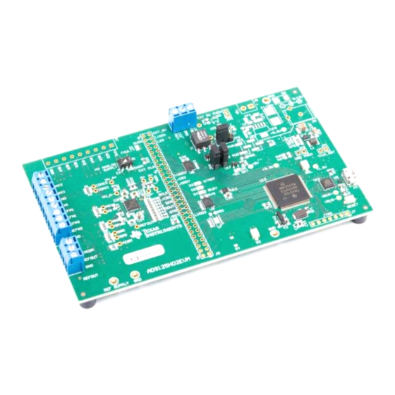
The ADS125H02 is a 2-channel, 24-bit, 40-kSPS, delta-sigma (ΔΣ) analog-to-digital converter (ADC) with
an integrated ±18-V programmable gain amplifier (PGA) with a 1-GΩ input impedance. The device also
includes a voltage reference and features to enhance data reliability such as cyclic redundancy check
(CRC) and signal monitors.
The ADS125H02EVM is an evaluation module kit providing hardware and software support for evaluation
of the ADS125H0x, delta-sigma analog-to-digital converter (ADC). The kit uses the Texas Instruments
TM4C1294NCPDT
over the USB interface. The software application is downloaded from the Texas Instruments website and
runs on the Windows operating system allowing for register manipulation and data collection from the
ADC. The ADS125H02EVM kit includes the ADS125H02 device along with a USB micro cable.
This document includes a detailed description of the hardware (HW), software, bill of materials, and
schematic for the EVM.
Throughout this document, the term EVM is synonymous with the ADS125H02EVM, demonstration kit,
and evaluation module. The term GUI is synonymous with Delta-Sigma ADC EvaluaTIon Software, core
application, and EVM software. The use of Tiva™ is synonymous with the TM4C1294NCPDT
microcontroller.
SBAU318A – October 2018 – Revised April 2019
Submit Documentation Feedback
ADS125H02 Evaluation Module
processor to communicate with the ADC via SPI and provide communication with a PC
Table 1. Related Documentation
Device
ADS125H02
Delta-Sigma ADC EvaluatTIon
Software User Manual
Copyright © 2018–2019, Texas Instruments Incorporated
SBAU318A – October 2018 – Revised April 2019
ADS125H02 Evaluation Module
Literature Number
SBAS790
SBAU260
User's Guide
ADS125H02 Evaluation Module
1
Advertisement
Table of Contents

Related Manuals for Texas Instruments ADS125H02


Summary of Contents for Texas Instruments ADS125H02
- Page 1 ADC via SPI and provide communication with a PC over the USB interface. The software application is downloaded from the Texas Instruments website and runs on the Windows operating system allowing for register manipulation and data collection from the ADC.
-
Page 2: Table Of Contents
ADS125H02 EVM Software Commands ....................... EVM Bill of Materials Trademarks Tiva is a trademark of Texas Instruments, Incorporated. Microsoft, Windows are registered trademarks of Microsoft Corporation. All other trademarks are the property of their respective owners. ADS125H02 Evaluation Module SBAU318A – October 2018 – Revised April 2019 Submit Documentation Feedback Copyright ©... -
Page 3: Evm Overview
EVM Overview www.ti.com EVM Overview Description This user's guide describes the operation and use of the ADS125H02 evaluation module. The EVM platform is intended for evaluating the ADS125H02 performance and functionality. Requirements 1.2.1 Software Requirements PC with Microsoft Windows 7 or higher operating system. -
Page 4: Quick Start
The EVM is powered through the USB interface with the PC. This power includes a +5-V and an HV supply generated onboard the EVM from the USB. Additionally, the HV supplies the ADS125H02 (±18 V to ±5 V), which can be powered from an external source from header connections on J4 through switch S1. - Page 5 High-Voltage Analog Supply Configuration of the ADC The ADS125H02 high-voltage supply requires a high-voltage power supply ranging from ±18 V to ±5 V for bipolar operation, or ranging from +36 V to +10 V for unipolar operation (when HV_AVSS = GND). An onboard HV supply generator supplies ±15 V from the USB connection.
-
Page 6: Hardware Reference
Spare button (not installed) Closed (depressed) Open (normally) Switch is DPDT. Pin 1 is identified with a dot on the PCB silkscreen. ADS125H02 Evaluation Module SBAU318A – October 2018 – Revised April 2019 Submit Documentation Feedback Copyright © 2018–2019, Texas Instruments Incorporated... -
Page 7: Input Terminal Blocks
2) to evaluate the performance of the ADS125H02. The functions for these terminal blocks are listed in Table 4. At no time apply a voltage to the inputs of the ADS125H02 that exceeds the absolute maximum ratings for the device. IDAC2... - Page 8 – – Analog inputs are pinned out to terminal blocks through RC filters. See Figure 19 for additional connection details. ADS125H02 Evaluation Module SBAU318A – October 2018 – Revised April 2019 Submit Documentation Feedback Copyright © 2018–2019, Texas Instruments Incorporated...
-
Page 9: High-Voltage Supply Terminal Block
EVM for evaluation purposes. The functions for these terminal blocks are listed in Table 5. Never apply a supply voltage that exceeds the absolute maximum ratings for the power supply of the ADS125H02. Figure 3. High-Voltage Supply Terminal Block Table 5. High-Voltage Supply Terminal Block, J4 Function... -
Page 10: Digital Interface, J5
HV analog supply (HV_AVDD supply side of sense resistor) HV_A+ Probe only HV analog supply (HV_AVDD device side of sense resistor) HV_A– Probe only ADS125H02 Evaluation Module SBAU318A – October 2018 – Revised April 2019 Submit Documentation Feedback Copyright © 2018–2019, Texas Instruments Incorporated... - Page 11 3.3-V output (U18) +3.3V Probe only Step-up transformer output (not populated) HVBoost Probe only Inverting transformer output (not populated) HVInvert Probe only SBAU318A – October 2018 – Revised April 2019 ADS125H02 Evaluation Module Submit Documentation Feedback Copyright © 2018–2019, Texas Instruments Incorporated...
-
Page 12: Software Details
Run the installer and follow the on-screen prompts. Future software versions may show slightly different screens. Figure 4. Delta-Sigma Evaluation Engine Installation Instructions ADS125H02 Evaluation Module SBAU318A – October 2018 – Revised April 2019 Submit Documentation Feedback Copyright © 2018–2019, Texas Instruments Incorporated... -
Page 13: Device Package Installation Instructions
Software Details www.ti.com 4.1.2 ADS125H02 EVM Device Package Download the ADS125H02 Device Package installer, as shown in Figure 5, from the ADS125H02EVM tool page for the ADS125H02EVM and save the file to a local folder. Run the appropriate device package installer and follow the on-screen prompts. -
Page 14: Gui View Before Connecting
GUI, an explanation of how to modify device register settings, how to collect and analyze data, and control device operations with scripts. For a list of commands that are supported on the ADS125H02 EVM, see Section 4.3.4. -
Page 15: Empty Register Map For An Unrecognized Device
GUI as shown in Figure Figure 10. Register Map for the ADS125H02 The ADS125H02 can be configured through the register map as well as through commands through the Console tab as described in Section 4.3.4. -
Page 16: Data Analysis Window
It is convenient to set the points/sample size in the lower left corner of the Data Analysis window to a lower value. The default sample size is 2048, while the default data rate for the ADS125H02 is 20 SPS. Collecting that amount of data takes over 100 seconds. -
Page 17: Ads125H02 Evm Software Commands
Command Description Arguments Device? Returns EVM ID string: "<DEVICE> <DATE> <TIME>", where "<DEVICE>" is "ADS125H02", and "<DATE> <TIME>" indicates when the EVM firmware was complied. COMMANDLIST Returns a list of all commands supported by the EVM firmware. Collects a number of ADC samples equal to "<# Samples>", where "<# Samples>" is an unsigned COLLECT <# Samples>... -
Page 18: Evm Bill Of Materials, Pcb Layouts, And Schematics
LED, Orange, SMD LED_0603 LTST-C191KFKT Lite-On D2, D3, D5 Green LED, Green, SMD LED_0603 LTST-C191TGKT Lite-On LED, Red, SMD LED_0603 LTST-C191KRKT Lite-On ADS125H02 Evaluation Module SBAU318A – October 2018 – Revised April 2019 Submit Documentation Feedback Copyright © 2018–2019, Texas Instruments Incorporated... -
Page 19: Evm Bill Of Materials
RES, 10.0 k, 1%, 0.1 W, 0603 0603 ERJ-3EKF1002V Panasonic 499k RES, 499 k, 1%, 0.1 W, 0603 0603 RC0603FR-07499KL Yageo America SBAU318A – October 2018 – Revised April 2019 ADS125H02 Evaluation Module Submit Documentation Feedback Copyright © 2018–2019, Texas Instruments Incorporated... - Page 20 CAP, CERM, 0.1 uF, 100 V, +/- 10%, X7R, 0603 0603 GRM188R72A104KA35D MuRata 2.2uF CAP, CERM, 2.2 uF, 10 V, +/- 10%, X7R, 0603 0603 GRM188R71A225KE15D MuRata ADS125H02 Evaluation Module SBAU318A – October 2018 – Revised April 2019 Submit Documentation Feedback Copyright © 2018–2019, Texas Instruments Incorporated...
- Page 21 Texas Instruments Precision, Analog Multiplexers, PW0016A (TSSOP-16) High-Precision Voltage Reference with Integrated High- VSSOP-8 REF6225IDGKR Texas Instruments Bandwidth Buffer, DGK0008A (VSSOP-8) SBAU318A – October 2018 – Revised April 2019 ADS125H02 Evaluation Module Submit Documentation Feedback Copyright © 2018–2019, Texas Instruments Incorporated...
- Page 22 Single Inverter Buffer/Driver With Open-Drain Output, DCK0005A DCK0005A SN74LVC1G06DCKT Texas Instruments Single Buffer/Driver With Open-Drain Output, DBV0005A (SOT- DBV0005A SN74LVC1G07DBVT Texas Instruments 23-5) ADS125H02 Evaluation Module SBAU318A – October 2018 – Revised April 2019 Submit Documentation Feedback Copyright © 2018–2019, Texas Instruments Incorporated...
-
Page 23: Top Silkscreen
PCB Layouts Figure 12 through Figure 17 illustrate the PCB layout. Figure 12. Top Silkscreen Figure 13. Top Layer (Positive) SBAU318A – October 2018 – Revised April 2019 ADS125H02 Evaluation Module Submit Documentation Feedback Copyright © 2018–2019, Texas Instruments Incorporated... -
Page 24: Ground Layer (Negative)
EVM Bill of Materials, PCB Layouts, and Schematics www.ti.com Figure 14. Ground Layer (Negative) Figure 15. Power Layer (Negative) ADS125H02 Evaluation Module SBAU318A – October 2018 – Revised April 2019 Submit Documentation Feedback Copyright © 2018–2019, Texas Instruments Incorporated... -
Page 25: Bottom Layer (Positive)
EVM Bill of Materials, PCB Layouts, and Schematics www.ti.com Figure 16. Bottom Layer (Positive) Figure 17. Bottom Silkscreen SBAU318A – October 2018 – Revised April 2019 ADS125H02 Evaluation Module Submit Documentation Feedback Copyright © 2018–2019, Texas Instruments Incorporated... -
Page 26: Ads125H02Evm Block Diagram Schematic
EVM Bill of Materials, PCB Layouts, and Schematics www.ti.com Schematic Figure 18 through Figure 25 illustrate the ADS125H02EVM schematics. Figure 18. ADS125H02EVM Block Diagram Schematic ADS125H02 Evaluation Module SBAU318A – October 2018 – Revised April 2019 Submit Documentation Feedback Copyright © 2018–2019, Texas Instruments Incorporated... -
Page 27: Ads125H02Evm Analog Inputs Header Schematic
EVM Bill of Materials, PCB Layouts, and Schematics www.ti.com Figure 19. ADS125H02EVM Analog Inputs Header Schematic SBAU318A – October 2018 – Revised April 2019 ADS125H02 Evaluation Module Submit Documentation Feedback Copyright © 2018–2019, Texas Instruments Incorporated... -
Page 28: Ads125H02Evm Adc Main Schematic
EVM Bill of Materials, PCB Layouts, and Schematics www.ti.com Figure 20. ADS125H02EVM ADC Main Schematic ADS125H02 Evaluation Module SBAU318A – October 2018 – Revised April 2019 Submit Documentation Feedback Copyright © 2018–2019, Texas Instruments Incorporated... -
Page 29: Ads125H02Evm Digital Header Schematic
EVM Bill of Materials, PCB Layouts, and Schematics www.ti.com Figure 21. ADS125H02EVM Digital Header Schematic SBAU318A – October 2018 – Revised April 2019 ADS125H02 Evaluation Module Submit Documentation Feedback Copyright © 2018–2019, Texas Instruments Incorporated... -
Page 30: Ads125H02Evm Usb And Peripherals Schematic
EVM Bill of Materials, PCB Layouts, and Schematics www.ti.com Figure 22. ADS125H02EVM USB and Peripherals Schematic ADS125H02 Evaluation Module SBAU318A – October 2018 – Revised April 2019 Submit Documentation Feedback Copyright © 2018–2019, Texas Instruments Incorporated... -
Page 31: Ads125H02Evm Processor Main Schematic
EVM Bill of Materials, PCB Layouts, and Schematics www.ti.com Figure 23. ADS125H02EVM Processor Main Schematic SBAU318A – October 2018 – Revised April 2019 ADS125H02 Evaluation Module Submit Documentation Feedback Copyright © 2018–2019, Texas Instruments Incorporated... -
Page 32: Ads125H02Evm Usb Power Schematic
EVM Bill of Materials, PCB Layouts, and Schematics www.ti.com Figure 24. ADS125H02EVM USB Power Schematic ADS125H02 Evaluation Module SBAU318A – October 2018 – Revised April 2019 Submit Documentation Feedback Copyright © 2018–2019, Texas Instruments Incorporated... -
Page 33: Ads125H02Evm External Power Schematic
EVM Bill of Materials, PCB Layouts, and Schematics www.ti.com Figure 25. ADS125H02EVM External Power Schematic SBAU318A – October 2018 – Revised April 2019 ADS125H02 Evaluation Module Submit Documentation Feedback Copyright © 2018–2019, Texas Instruments Incorporated... - Page 34 Changed first sentence of Powering Up the EVM section ....................• Changed EVM Bill of Materials table ............• Added Header to ADS125H02EVM Analog Inputs Header Schematic title Revision History SBAU318A – October 2018 – Revised April 2019 Submit Documentation Feedback Copyright © 2018–2019, Texas Instruments Incorporated...
- Page 35 STANDARD TERMS FOR EVALUATION MODULES Delivery: TI delivers TI evaluation boards, kits, or modules, including any accompanying demonstration software, components, and/or documentation which may be provided together or separately (collectively, an “EVM” or “EVMs”) to the User (“User”) in accordance with the terms set forth herein.
- Page 36 www.ti.com Regulatory Notices: 3.1 United States 3.1.1 Notice applicable to EVMs not FCC-Approved: FCC NOTICE: This kit is designed to allow product developers to evaluate electronic components, circuitry, or software associated with the kit to determine whether to incorporate such items in a finished product and software developers to write software applications for use with the end product.
- Page 37 www.ti.com Concernant les EVMs avec antennes détachables Conformément à la réglementation d'Industrie Canada, le présent émetteur radio peut fonctionner avec une antenne d'un type et d'un gain maximal (ou inférieur) approuvé pour l'émetteur par Industrie Canada. Dans le but de réduire les risques de brouillage radioélectrique à...
- Page 38 www.ti.com EVM Use Restrictions and Warnings: 4.1 EVMS ARE NOT FOR USE IN FUNCTIONAL SAFETY AND/OR SAFETY CRITICAL EVALUATIONS, INCLUDING BUT NOT LIMITED TO EVALUATIONS OF LIFE SUPPORT APPLICATIONS. 4.2 User must read and apply the user guide and other available documentation provided by TI regarding the EVM prior to handling or using the EVM, including without limitation any warning or restriction notices.
- Page 39 Notwithstanding the foregoing, any judgment may be enforced in any United States or foreign court, and TI may seek injunctive relief in any United States or foreign court. Mailing Address: Texas Instruments, Post Office Box 655303, Dallas, Texas 75265 Copyright © 2019, Texas Instruments Incorporated...
- Page 40 TI products. TI’s provision of these resources does not expand or otherwise alter TI’s applicable warranties or warranty disclaimers for TI products. Mailing Address: Texas Instruments, Post Office Box 655303, Dallas, Texas 75265 Copyright © 2019, Texas Instruments Incorporated...