Advertisement
Quick Links
- Wiring Brochure
tekmarNet
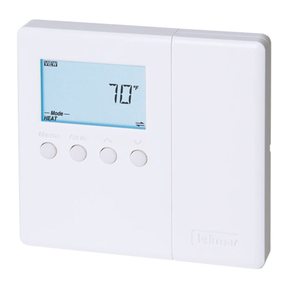
4 Thermostat 543
®
1
2
Information
Application
Brochure
Choose controls
Design your
to match
mechanical
application
applications
Overview
The following brochure describes how to wire the tekmar tekmarNet
heat stages. The 543 has inputs for two auxiliary sensors. The wiring of 543 thermostat is simple and cost effective.
Auxiliary
Sensors
tN4
Network
Table of Contents:
Definitions .......................................................................2
Rough-In Wiring .............................................................2
Remove the Wiring Cover ..............................................3
Mounting the Thermostat ...............................................3
Wiring Symbols ...............................................................3
3
Layout
Brochure
Brochure
Rough-in
wiring
instructions
DIP
Switches
24 V (ac)
Power
4
Wiring
Brochure
Wiring and
installation of
specific control
4 (tN4) thermostat 543. The 543 has outputs for two
®
S2
S1
Com
tN4
C
R
Rh1
W1
Rh2 W2
1st Stage
Heating
Electrical Drawings ......................................................3-5
Wiring the Thermostat .................................................6-7
Troubleshooting the Wiring .............................................7
Testing the Wiring ........................................................7-8
Technical Data ................................................................8
1 of 8
5
6
Data
Brochure
Control settings
Record settings &
and sequence of
wiring details for
operation
future reference
Wiring
Cover
tNt 543
Two Stage Heat
Power: 24 V (ac) ±10% 60 Hz 2.5 VA
Relays: 24 V (ac) 2 A
994-01
Meets Class B: Canadian ICES, FCC Part 15
Terminal Functions
S2
Sensor 2
S1
Sensor 1
Com
Sensor Common
To isolate
tN4
tekmarNet 4
®
relay, cut
C
Power Neutral
jumper
R
Power 24 V (ac)
Rh1
Heat 1 Relay
W1
Heat 1 Relay
Rh2
Heat 2 Relay
W2
Heat 2 Relay
DIP Switch Functions
2nd Stage
Heating
© 2008
W 543
12/08
Job
Record
W 543 - 12/08
Advertisement

Related Manuals for Tekmar tekmarNet 4 543


Summary of Contents for Tekmar tekmarNet 4 543
-
Page 1: Table Of Contents
Overview The following brochure describes how to wire the tekmar tekmarNet 4 (tN4) thermostat 543. The 543 has outputs for two ® heat stages. The 543 has inputs for two auxiliary sensors. The wiring of 543 thermostat is simple and cost effective. -
Page 2: Definitions
Defi nitions The following defined terms and symbols are used throughout this manual to bring attention to the presence of hazards of various risk levels, or to important information concerning the life of the product. – Caution: Refer to accompanying documents. –... -
Page 3: Remove The Wiring Cover
Remove the Wiring Cover: To remove the wiring cover: • Place a small slot screwdriver or similar tool into the slot located on the right side of the thermostat. • While pushing against the plastic tab, lift off the wiring cover. - Page 4 Electrical Application 543 E1 Description: Two Stage Heating (H1 = Radiant, H2 = Fin-tube Convector or Fan Coil). Legend: Sensor 1 = Floor Sensor 2 = Outdoor 543 tNt tNt 543 Two Stage Heat Power: 24 V (ac) ±10% 60 Hz 2.5 VA Relays: 24 V (ac) 2 A 994-01 Meets Class B: Canadian ICES, FCC Part 15...
- Page 5 Electrical Application 543 E2 Description: Two Stage Heating (H1 = Radiant, H2 = Furnace). Legend: Sensor 1 = Remote HVAC Equipment Sensor 2 = Room 543 tNt tNt 543 Two Stage Heat Power: 24 V (ac) ±10% 60 Hz 2.5 VA Relays: 24 V (ac) 2 A 994-01 Meets Class B: Canadian ICES, FCC Part 15...
-
Page 6: Wiring The Thermostat
Wiring the Thermostat: Power (24 V (ac)) Terminals 5, 6 Wire 24 V (ac) to terminals C and R. Thermostat If a Zone Manager is used: • Connect C on the thermostat to C on the proper zone of the Zone Manager. •... -
Page 7: Troubleshooting The Wiring
Auxiliary Sensors Terminals 1 - 3 The auxiliary sensors are connected to the thermostat on terminals Com, S1 and S2. To various tekmar Universal sensors • • Connect sensor 1 to terminals S1 and Com. Sensor Thermostat • • Connect sensor 2 to terminals S2 and Com. - Page 8 None – Optional tekmar type # 071, 070, 072, 073, 076, 077, 078, 079 The installer must ensure that this control and its wiring are isolated and / or shielded from strong sources of electromag- netic noise. Conversely, this Class B digital apparatus complies with Part 15 of the FCC Rules and meets all requirements of the Canadian Interference-Causing Equipment Regulations.