Table of Contents
Advertisement
Quick Links
- Wiring Brochure
tekmarNet
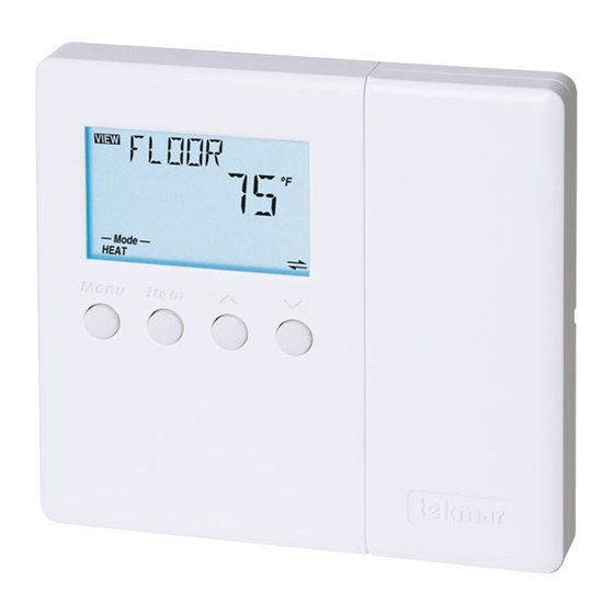
4 Thermostat 544
®
1
2
Information
Application
Brochure
Choose controls
Design your
to match
mechanical
application
applications
Overview
The following brochure describes how to wire the tekmar tekmarNet
one heat stage, one cooling stage and one fan. The 544 has inputs for two auxiliary sensors. The wiring of 544 thermostat
is simple and cost effective.
Auxiliary
Sensors
tN4
Network
Table of Contents:
Definitions .......................................................................2
Rough-In Wiring .............................................................2
Remove the Wiring Cover ..............................................3
Mounting the Thermostat ...............................................3
Wiring Symbols ...............................................................3
3
Layout
Brochure
Brochure
Rough-in
wiring
instructions
DIP
Switches
24 V (ac)
Power
4
Wiring
Brochure
Wiring and
installation of
specific control
®
4 (tN4) thermostat 544. The 544 has outputs for:
1st Stage
Cooling
Y1 Rc G1 G1
Com
S2
S1
tN4
C
R
Rh1
W1
1st Stage
Heating
Electrical Drawings ......................................................3-7
Wiring the Thermostat .................................................8-9
Troubleshooting the Wiring ........................................... 10
Testing the Wiring ......................................................... 11
Technical Data .............................................................. 12
1 of 12
5
6
Data
Brochure
Control settings
Record settings &
and sequence of
wiring details for
operation
future reference
1st Stage
Wiring
Fan
Cover
tNt 544
One Stage Heat, One Stage Cool, One Fan
Power: 24 V (ac) ±10% 60 Hz 1.5 VA
Relays: 24 V (ac) 2 A
992-03
Meets Class B: Canadian ICES, FCC Part 15
Terminal Functions
G1
Fan 1 Relay
G1
Fan 1 Relay
Rc
Power Cooling
Y1
Cool 1 Relay
Com
Sensor Common
S2
Sensor 2
S1
Sensor 1
tN4
tekmarNet 4
C
Power Neutral
R
Power 24 V (ac)
Rh1
Heat 1 Relay
W1
Heat 1 Relay
To isolate
relay, cut
jumper
DIP Switch Functions
© 2008
W 544
12/08
Job
Record
®
W 544 - 12/08
Advertisement
Table of Contents

Related Manuals for Tekmar tekmarNet 4 544


Summary of Contents for Tekmar tekmarNet 4 544
-
Page 1: Table Of Contents
Overview The following brochure describes how to wire the tekmar tekmarNet ® 4 (tN4) thermostat 544. The 544 has outputs for: one heat stage, one cooling stage and one fan. The 544 has inputs for two auxiliary sensors. The wiring of 544 thermostat is simple and cost effective. -
Page 2: Definitions
Defi nitions The following defined terms and symbols are used throughout this manual to bring attention to the presence of hazards of various risk levels, or to important information concerning the life of the product. – Caution: Refer to accompanying documents. –... -
Page 3: Remove The Wiring Cover
Remove the Wiring Cover: To remove the wiring cover: • Place a small slot screwdriver or similar tool into the slot located on the right side of the thermostat. • While pushing against the plastic tab, lift off the wiring cover. - Page 4 Electrical Application 544 E1 Description: One Stage Heating (H1 = Radiant), One Stage Cooling (C1 = Compressor), One Speed Fan (F1 = C1), Fan Mode = 1. Legend: Sensor 1 = Floor Sensor 2 = Outdoor Cooling Equipment 1 Stage Cooling 1 Stage Fan Rc Y1 G1 544 tNt...
- Page 5 Electrical Application 544 E2 Description: One Stage Heating (H1 = Radiant), One Stage Cooling (C1 = Compressor & Fan), One Ventilation Fan (F1 = Vent), Fan Mode = None. Legend: Sensor 1 = Room Sensor 2 = Floor Cooling Equipment 1 Stage Cooling with Fan Ventilation...
- Page 6 Electrical Application 544 E3 Description: One Stage Heating (H1 = Coil), One Stage Cooling (C1 = Coil), One Speed Fan (F1 = H1 & C1), Fan Mode = 2. Legend: Sensor 1 = Remote Sensor 2 = Room Cooling Coil G1 G1 544 tNt tNt 544...
- Page 7 Electrical Application 544 E4 Description: One Stage Heating (H1 = Furnace), One Stage Cooling (C1 = Compressor), One Speed Fan (F1 = H1 & C1), Fan Mode = 2. Legend: Sensor 1 = Remote Sensor 2 = Outdoor HVAC Equipment 1 Stage Heat 1 Stage Cooling 1 Stage Fan...
-
Page 8: Wiring The Thermostat
Wiring the Thermostat: Power (24 V (ac)) Terminals 9, 10 Wire 24 V (ac) to terminals C and R. Thermostat If a Zone Manager is used: • Connect C on the thermostat to C on the proper zone of the Zone Manager. •... - Page 9 • Use these terminals as a switch to operate the first stage Rc G1 G1 of fan. 1st Stage Auxiliary Sensors Terminals 5 - 7 The auxiliary sensors are connected to the thermostat on To various tekmar Thermostat terminals Com, S1 and S2. Universal sensors Sensor 5 Com •...
-
Page 10: Troubleshooting The Wiring
Troubleshooting the Wiring General The following tests are to be performed using standard 5 Com testing practices and procedures and should only be carried 6 S2 Y1 Rc G1 G1 out by properly trained and experienced persons. 7 S1 A good quality electrical test meter, capable of reading 8 tN4 from at least 0 - 300 V (ac), 0 - 2,000,000 Ohms, and testing for continuity is essential to properly test the wiring and... -
Page 11: Testing The Wiring
Testing the Wiring Testing 24 V (ac) Power Supply 1. Remove the front cover from the thermostat. 2. Use an electrical test meter to measure (ac) voltage between the R and C terminals. The reading should be 24 V (ac) +/–... -
Page 12: Technical Data
None – Optional tekmar type # 070, 071, 072, 073, 076, 077, 078, 079, 082, 084 The installer must ensure that this control and its wiring are isolated and / or shielded from strong sources of electromag- netic noise. Conversely, this Class B digital apparatus complies with Part 15 of the FCC Rules and meets all requirements of the Canadian Interference-Causing Equipment Regulations.