
Related Manuals for Dimplex WFE3BE


Summary of Contents for Dimplex WFE3BE
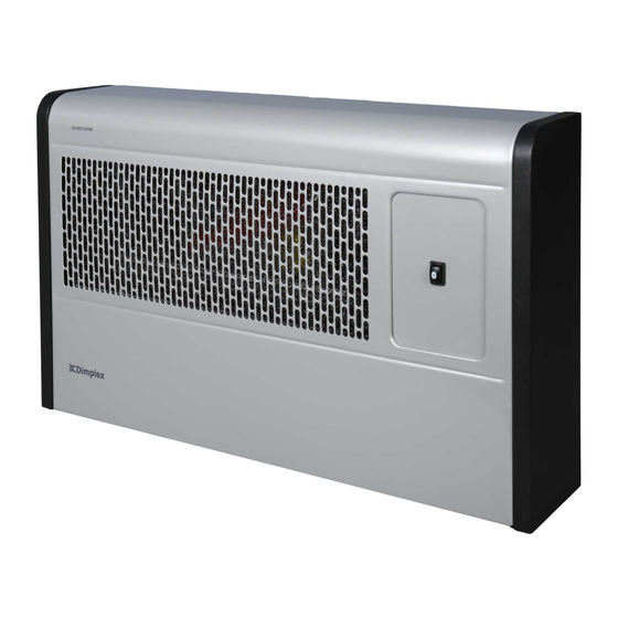
- Page 1 INSTRUCTION MANUAL Installation and Operating WFE Wall Fan Convector Model: WFE3BE, WFE3SE This product is supplied and operated with a Bluetooth Remote Control handset 08/53943/0 ISSUE: 1...
- Page 2 IMPORTANT THESE INSTRUCTIONS SHOULD BE READ CAREFULLY AND RETAINED FOR FUTURE REFERENCE. Note also the information presented on the appliance CAUTION: FAILURE TO FOLLOW THESE ISTRUCTIONS MAY CAUSE INJURY AND/OR DAMAGE AND MAY INVALIDATE YOUR GUARANTEE WARNING – This appliance must not be used in a bathroom. WARNING –...
- Page 3 normal operating position and they have been given supervision or instruction concerning the use of the appliance in a safe way and understand the hazards involved. Children aged from 3 years and less than 8 years shall not plug in, regulate and clean the appliance or perform user maintenance.
-
Page 4: Technical Details
This product complies with Lot20 of the Energy Efficiency Directive (2015/1188). Type of heat output/ room temperature control Electronic room temperature control plus week timer With open window detection With adaptive start control Technical Details Model Identifier(s): WFE3BE WFE3SE Nominal heat output Pnom 3.0kW 3.0kW Height (mm) - Page 5 ~230-240 V, 50Hz Class I, with earth wire • Black body with Cherry wood side panels Colour / Finish • Silver body with Black side panels Approvals CE, BEAB Warranty 2 years Country of Origin British Isles Manufacturer Glen Dimplex Heating & Ventilation (GDC Group Ltd.)
-
Page 6: Installation
Installation WARNING: The installation of this appliance should be carried out by a competent electrician and be in accordance with the current IEE wiring regulations and any local or insurance regulations. Before undertaking installation work, ensure the electricity supply is disconnected from any relevant fixed wiring. - Page 7 Fig. 1 350mm Fig. 2 shelf 571mm 150mm min 10mm 510mm 350mm 35mm ‘A’ 350mm...
- Page 8 Electrical WARNING: This appliance must be earthed After ensuring the electricity supply is not live, electrical connections can be made, either to an adjacent double-pole switch having a contact separation of at least 3mm in all poles or to a plug-top for use in a standard 13A socket. If the latter: Connect Green and Yellow wire to plug terminal marked E or Green or Green and Yellow.
-
Page 10: Remote Control
Remote Control The product is supplied with a Bluetooth remote control, the remote control should be contained in the carrier bag along with these instructions. This remote control is required to operate the appliance. When paired with the remote control various operational modes and features can be accessed. - Page 11 Fitting the Batteries: The remote requires two AA batteries, these are supplied with the product contained in the bag along with the instructions and remote. To fit the batteries: 1. On the rear of the remote, remove the battery cover by pushing the catch downwards and pulling outwards in one motion.
- Page 12 Remote Pairing Instructions To pair the product to the Bluetooth remote: 1. Press the Bluetooth button which is located on the front of the product. The product will emit a beep and begin to broadcast a signal to be paired via Bluetooth. NOTE: If no remote pairs within 2 minutes, the product will stop broadcasting.
-
Page 13: Setting Time And Date
Setting Time & Date After initial remote control start up and after replacing the batteries it is required to set the time and date. It is not possible to navigate to the home screen and product settings until the time and date have been set. It is possible to modify these settings at any stage from within the menu structure, see page 19. -
Page 15: Operation
Operation The product is controlled using the remote control. The remote consists of a display screen and six touch sensitive buttons. The function of each button and the meaning of each screen icon is explained in the graphic below. The remote offers fully programmable time and temperature control with a host of additional useful control features. -
Page 16: Operating Modes
Waking from Standby Mode When in standby mode, holding ENTER for two seconds will wake the remote and attempt to reconnect to the product, this will be signified by the connectivity icon and loading graphic appearing on the screen. Operating Modes The remote control provides the option of a number of standard control modes, •... -
Page 17: Home Screen
Home Screen Typically the Home Screen will display the active operational mode, the desired room temperature set-point and the heating status. Any of the Advance function which are active will also be displayed on the home screen. Pressing ENTER while on the Home screen will display the current time.. -
Page 18: Thermostat Control
Navigation and Selecting Modes The remote control and menus are navigated using the six button keypad. In order to select/ change operational mode, press the MENU button. The remote will then enter the basic menu structure, this menu provides the option to quickly select the following options, each option is represented by an icon. - Page 19 Heat Output Selection The remote control offers the facility to select the heat output from the appliance between HI and LO heat settings, HI heat is set by default. This is a global heat setting and once set all other operational modes will operate with this setting. In order to set/change the heat setting, •...
-
Page 20: Timer Mode
Timer Mode The Timer offers the most efficient mode of operation for a predictable heat demand. The user has the flexibility program up to four distinct time and temperature profiles per day, per week. The user has the ability to adjust the temperature during any heating period and additional functions such as ‘Advance’... - Page 21 Setting/Modifying the Time Profiles • Press the MENU key from the home screen. • Use the arrow keys to highlight the Schedule Icon, • Press ENTER to enter Timer Settings. • Use the arrow keys to highlight ‘ Edit’ and Press ENTER again to confirm selection. •...
- Page 22 Copy and Paste Time profiles It is possible to copy the complete time profile from one day and paste it to another day. This will copy all four program periods and associated time and temperatures. To copy and paste a day profile: •...
- Page 23 Continuous Heat Modes A Continuous Heat mode is effectively a constant heat control period. The heater will maintain a pre determined room temperature indefinitely irrespective of time until the mode is changed by the User. Available Continuous Heat Modes Each continuous heat profile is preloaded with a default Target Temperature value but is fully adjustable.
- Page 24 Frost Protect This mode maintains a constant room temperature of 7°C. This mode is not intended for human comfort and should be used to provide protection against frost. This mode is indicated by the Frost icon. To activate Frost Protect mode: •...
- Page 25 Advanced Mode Functions These functions modify the normal behaviour of the appliances operational modes. The advanced functions available will depend on the active operation mode, for example an advance function is only available when timer mode is operational and similarly a runback function is only available for continuous heating modes.
- Page 26 Runback The Runback mode will assign a timed period to a continuous heating mode. Once this time period has elapsed the appliance will revert to Comfort Off mode. When runback has been activated and the ADV key is pressed from a continuous heating mode then it is possible to select between four available time durations.
-
Page 27: Advanced Menu
Advanced Menu The advanced menu contains several additional settings required for non standard applications and installation. It is from within this menu the runback function can be activated and the details can be setup. Setback, PIN lock and advanced start options are also controlled from this menu. - Page 28 • You will be required to select a Maximum Runback Duration, this value can be selected from the pre programmed list. Each Max Duration will provide four selectable runback periods. See the table below for a break down of the options available: Maximum Selectable Runback options...
- Page 29 Setback Settings Setback is a function that only modifies Timer Mode operation. When Setback is enabled it overrides any Heating Off period to maintain a constant temperature during Heating Off periods. This can be used to prevent the room temperature from falling below a minimum value while there is no demand for heat (Heating On).
- Page 30 Adaptive Start Adaptive Start is a predictive function that only modifies Timer Mode operation. This function models the heating characteristics of the room and uses that information to pre-heat the room to ensure the target temperature has been reached by the start of the Heating On period.
- Page 31 PIN Lock This locking method utilises a PIN code that is set by the User. When activated, the appliance is locked in the previously active mode and user will be restricted to basic functions. In order to change the mode or settings the PIN code must be re entered. It is important that all required parameters such as time profiles and/or temperatures are set and the desired mode is activated before applying the PIN lock.
- Page 32 NOTE: Once the PIN has been set you will be required to re-enter the PIN if any button is pressed. The only exception is when the criteria has been met to allow runback mode using the ADV key. Exiting PIN Lock mode •...
-
Page 33: Service Settings
Service Settings Temperature Settings To choose whether the remote displays degrees Celsius or degrees Fahrenheit: • Hold down the MENU button for 2 seconds • Use the arrow keys to toggle C or The highlighted option will be flashing. • Press ENTER to confirm your selection and return to the home screen Appliance ID &... - Page 34 Factory Reset If you wish to either reset the heater to default values, or disconnect and restore default values of the Bluetooth remote: • Hold down Up and Down buttons at the same time for 5 seconds to enter “Fr” (Factory Reset) options.
-
Page 35: Error Codes
Error Codes If an error code (Er 20) appears flashing on the remote screen, this indicates that there has been an issue with the room temperature sensor. Please contact customer service. . Maintenance Battery Replacement IMPORTANT Battery should be disposed of in an appropriate manner see section for fitting batteries. - Page 36 Maintenance WARNING: THE INTERNAL CLEANING AND MAINTENANCE WORK SHOULD ONLY BE UNDERTAKEN BY COMPETENT PERSONS WITH EXPERIENCE OF Service and Repair REPAIRING DOMESTIC ELECTRICAL APPLIANCES AND IN FULL KNOWLEDGE OF THE POSSIBLE HAZARDS INVOLVED. To ensure the appliance operates efficiently, the following maintenance should be undertaken periodically.
- Page 37 Fig. 4 Important For electrical products sold within the European Community. At the end of the electrical products useful life it should not be disposed of with household waste. Please recycle where facilities exist. Check with a Local Authority or retailer for recycling advice in your country.
-
Page 38: Warranty
Once we receive your information and proof of purchase we will contact you to make the necessary arrangements. If your Dimplex product is not covered by this Dimplex Warranty there may be a charge to repair your product. However, we will contact you for agreement to any charges before any chargeable service is carried out. - Page 39 • You must provide to Dimplex or its authorised agents on request the original receipt as proof of purchase and - if required by Dimplex - proof of delivery. If you are unable to provide this documentation, you will be required to pay for any repair work required.
- Page 40 Glen Dimplex Heating and Ventilation Millbrook House, Grange Drive, Hedge End, Southampton, SO30 2DF © Glen Dimplex. All rights reserved. Material contained in this publication may not be reproduced in whole or in part, without prior permission in writing of Glen Dimplex...