Advertisement
Quick Links
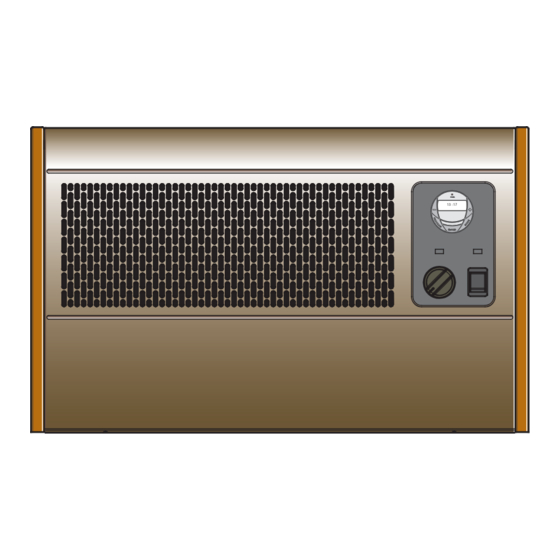
Dimplex Wall-mounted Fan Convector
Model(s) : WFE 3TNB and WFE 3TNS
Dimensions
(millimetres)
Model(s)
Specification
WFE 3TNB
3kW, Switch, Thermostat & 7 Day Timer - Black
WFE 3TNS
3kW, Switch, Thermostat & 7 Day Timer - Silver
THESE INSTRUCTIONS SHOULD BE READ CAREFULLY AND RETAINED FOR FUTURE REFERENCE
Important Safety Advice
WARNING – THIS APPLIANCE MUST NOT BE USED IN A
BATHROOM.
WARNING – DO NOT USE THIS HEATER IN THE IMMEDIATE
SURROUNDINGS OF A BATH, A SHOWER OR A SWIMMING POOL.
WARNING – THIS HEATER MUST NOT BE LOCATED IMMEDIATELY
ABOVE OR BELOW A FIXED SOCKET OUTLET.
DO NOT USE THE HEATER UNTIL IT IS WALL MOUNTED
CORRECTLY.
The heater carries a warning 'Do Not Cover' to alert the user
to the risk of overheating that exists if the heater is
accidentally covered.
Keep combustible materials such as drapes and other
furnishings clear from the front of the heater. Do not use
heater to dry your laundry.
NEVER cover or obstruct in any way the air inlet slots at the
front of the heater or the heat outlet slots in the base of the
heater.
This appliance is not intended for use by children or other
persons without assistance or supervision if their physical,
sensory or mental capabilities prevent them from using it
safely. Children should be supervised to ensure that they
do not play with the appliance.
If young children, the aged, or infirm are likely to be left in
the vicinity of the heater, we advise that adequate
precautions should be taken. We recommend that a guard
be fitted to ensure contact with the heater is avoided and
objects cannot be inserted into the product.
WARNING: In order to avoid a hazard due to inadvertent
resetting of the thermal cut-out, this appliance must not be
supplied through an external switching device, such as a
timer, or connected to a circuit that is regularly switched on
and off by the utility.Do not use where excessive dust or
moisture is present.
Do not use where excessive dust or moisture is present.
For further information, please contact our guard supplier
direct on Tel. No. 01603 667957, or in the case of difficulty or
for further advice contact our Customer Helpline.
Installation
Before undertaking installation work, ensure the electricity
supply is disconnected from any relevant fixed wiring.
Supply cable is not provided with this appliance, and a competent
electrician should therefore install it.
The appliance must be fitted horizontally with the cable or conduit entry
at bottom right. It should be mounted such that the underside is at least
350mm above the floor and the top of the heater is 150mm below any
Installation and Operating Instructions
Fig. 1
overhanging shelf or obstruction.
This heater must be used on an A.C.~ supply only and the voltage
marked on the heater must correspond to the supply voltage.
To comply with the I.E.E. Wiring Regulations, the appliance must be
earthed; the supply circuit must be adequate for the input of the appliance,
and the circuit protected by a suitable 13A fuse. A suitable termination to
the fixed wiring of the premises must be provided adjacent to the final
position of the appliance. In this instance, such a termination can be a
double-pole switch with a contact separation of at least 3mm in all
poles.
The heater must not be located immediately below a fixed
socket-outlet.
Electrical
WARNING : THIS APPLIANCE MUST BE EARTHED.
After ensuring the electricity supply is not live, electrical connections
can be made, either to an adjacent double-pole switch having a contact
separation of at least 3mm in all poles or to a plug-top for use in a
standard 13A socket.
If the latter: Connect Green and Yellow wire to plug terminal marked 'E'
or
Green or Green and Yellow. Connect Blue wire to plug
terminal marked 'N' or Black. Connect Brown wire to plug terminal
marked 'L' or Red.
Refit cover, first hooking top over the unit and then securing bottom by
refitting the two screws under the bottom edge. The appliance is now
ready for use and the electricity supply can be reinstated.
Fixing dimensions
shelf
150mm min
08/18748/6 (UK)
571mm
13 : 17
571mm
510mm
'A'
Issue 6
shelf
150mm min.
120mm
350mm
350mm min.
6mm
Ø
8mm
10mm
350mm
280mm
35mm
350mm min.
Fig. 2
Advertisement

Related Manuals for Dimplex WFE 3TNB


Summary of Contents for Dimplex WFE 3TNB
- Page 1 Installation and Operating Instructions Dimplex Wall-mounted Fan Convector 08/18748/6 (UK) Issue 6 Model(s) : WFE 3TNB and WFE 3TNS Dimensions (millimetres) shelf Model(s) Specification 571mm 150mm min. 120mm WFE 3TNB 3kW, Switch, Thermostat & 7 Day Timer - Black WFE 3TNS 3kW, Switch, Thermostat &...
- Page 2 Procedure Digital Timer Operation - see Fig. 6 Release the front cover from the unit by undoing the two screws under IMPORTANT: DO NOT plug in the appliance where the load the bottom edge. exceeds 16 Amp. Carefully remove cover by pulling bottom-front forward, and then lift to release top from retaining slots.
- Page 3 Set Time Key Lock 1. Press the ‘Program’ button To lock the keypad press ENTER and 00 : 00 00 : 00 ONCE. The clock symbol MODE simultaneously. The key appears on the top left hand symbol will appear on the screen side of the screen - see Fig.
- Page 4 Tel. 01 8424833 SO30 2DF www.thorneanderrick.co.uk [c] GDC Group Ltd, All rights reserved. Material contained in this publication may not be reproduced in whole or in part, without prior permission in writing of Dimplex. A division of GDC Group Ltd,...