
Related Manuals for Lenovo ThinkCentre M820z


Summary of Contents for Lenovo ThinkCentre M820z
- Page 1 M820z User Guide and Hardware Maintenance Manual Energy Star Machine Types: 10SC, 10SD, 10Y7, and 10Y8...
- Page 2 Important Product Information Guide and Appendix A “Notices” on page 57. First Edition (July 2018) © Copyright Lenovo 2018. LIMITED AND RESTRICTED RIGHTS NOTICE: If data or software is delivered pursuant to a General Services Administration “GSA” contract, use, reproduction, or disclosure is subject to restrictions set forth in Contract No. GS-...
-
Page 3: Table Of Contents
Appendix B. Trademarks ..59 Replacing the side I/O bezel ..Replacing the system board shield ..© Copyright Lenovo 2018... - Page 4 M820z User Guide and Hardware Maintenance Manual...
-
Page 5: Chapter 1. Overview
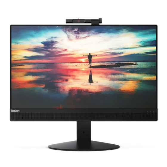
Always On USB 3.1 Gen 2 connector (for rapid charge) USB 3.1 Gen 1 Type-C connector Headset connector (also known as combo audio jack) Power button Microphone mute/unmute control Power indicator Storage drive activity indicator Microphone mute/unmute indicator Internal speakers (2) Screen Integrated microphones © Copyright Lenovo 2018... - Page 6 Used to record sounds or use speech-recognition software without using a microphone. Integrated camera activity indicator When the indicator is on, the camera is in use. Integrated camera shield control slider Used to cover the camera lens. Integrated camera Used to take pictures or hold a video conference. Card reader slot Used to read data from a supported memory card.
-
Page 7: Rear View
Used to listen to the sounds from your computer without using a headset or headphones. Screen Depending on the computer model, your computer screen might support the multi-touch feature. This feature enables you to use up to ten fingers to interact with the computer. Rear view Note: Your computer model might look slightly different from the illustration. -
Page 8: System Board
Used to connect the power cord to your computer for power supply. Ethernet connector Used to connect an Ethernet cable for network access. USB 3.1 Gen 1 connector Used to connect a USB-compatible device. For optimal data transfer, connect a USB 3.1 Gen 1 device to a USB 3.1 Gen 2 or USB 3.1 Gen 1 connector instead of a USB 2.0 connector. - Page 9 Figure 3. System board Integrated camera module connector Microprocessor socket Memory slot (DIMM1) Memory slot (DIMM2) M.2 solid-state drive slot System fan connector LCD LVDS connector Touch board connector SATA power connector (connecting to the storage Power supply assembly connector drive and optical drive) Cover presence switch connector (intrusion switch Coin-cell battery...
-
Page 10: Machine Type And Model Label
Machine type and model label The machine type and model label identifies the computer. When you contact Lenovo for help, the machine type and model information helps support technicians to identify the computer and provide faster service. The machine type and model label is attached on the computer as shown. - Page 11 Full-function monitor stand Figure 5. Tilting the screen forward and back Figure 6. Adjusting the height of the screen Figure 7. Turning the screen to the left and right Chapter 1 Overview...
- Page 12 UltraFlex III Stand Figure 8. Tilting the screen forward and back Figure 9. Pressing the screen downward after tilting it back Figure 10. Turning the screen to the left and right M820z User Guide and Hardware Maintenance Manual...
-
Page 13: Chapter 2. Specifications
Physical dimensions (without the computer stand) • Width: 491.1 mm (19.3 inches) • Height: 342.4 mm (13.5 inches) • Depth: 49.3 mm (1.9 inches) Weight (with the computer stand) (without the package) Maximum configuration as shipped: 7.9 kg (21.7 lb) © Copyright Lenovo 2018... - Page 14 M820z User Guide and Hardware Maintenance Manual...
-
Page 15: Chapter 3. Computer Locks
The cable lock also locks the buttons used to open the computer cover. This is the same type of lock used with many notebook computers. You can order such a cable lock directly from Lenovo by searching for Kensington at: http://www.lenovo.com/support Figure 11. - Page 16 M820z User Guide and Hardware Maintenance Manual...
-
Page 17: Chapter 4. Replacing Hardware
• When installing or replacing an option, use the appropriate instructions explained in this manual along with the instructions that come with the option. • In most areas of the world, Lenovo requires the return of defective CRUs. Information about this will come with the CRU or will come a few days after the CRU arrives. -
Page 18: Locating Frus (Including Crus)
Locating FRUs (including CRUs) Notes: • Some of the following components are optional. • To replace a component that is not in the list below, contact a Lenovo service technician. For a list of Lenovo Support phone numbers, go to: http://www.lenovo.com/support/phone... - Page 19 Figure 12. Locating FRUs (including CRUs) Self-service CRUs Optional-service CRUs Non-CRUs UltraFlex III Stand System board shield Optical drive and storage drive cables Full-function monitor stand Optical drive VESA mount bracket Computer cover Optical drive bezel Optical drive holder Storage drive bracket M.2 solid-state drive Power supply assembly Storage drive...
-
Page 20: Replacing The Computer Stand
Self-service CRUs Optional-service CRUs Non-CRUs Mouse Side I/O bezel Back frame Power cord Chassis LCD panel Backlight cable Touch cable Wi-Fi antennas (2) LVDS cable Front decorative cover Internal speakers (2) Thermal pads(2) Serial connector module Wi-Fi card shield Wi-Fi card System board Card reader Microprocessor... - Page 21 Figure 13. Removing the full-function monitor stand Figure 14. Installing the full-function monitor stand • UltraFlex III Stand Figure 15. Removing the UltraFlex III Stand Chapter 4 Replacing hardware...
-
Page 22: Removing The Computer Cover
Figure 16. Installing the UltraFlex III Stand 5. Place the computer in an upright position. 6. Reconnect the external cables and power cords to the corresponding connectors on the computer. Removing the computer cover Attention: Do not open your computer or attempt any repairs before reading the Important Product Information Guide. -
Page 23: Replacing The Storage Drive
6. Remove the computer cover. Figure 17. Removing the computer cover 7. Complete the replacement. See “Completing the parts replacement” on page 55. Replacing the storage drive Attention: Do not open your computer or attempt any repairs before reading the Important Product Information Guide. - Page 24 Figure 19. Removing the storage drive from the bracket Figure 20. Installing the storage drive into the bracket M820z User Guide and Hardware Maintenance Manual...
-
Page 25: Replacing The Optical Drive
Figure 21. Installing the storage drive and the bracket 5. Connect the signal cable and the power cable to the new storage drive. 6. Reinstall the removed parts. To complete the replacement, see “Completing the parts replacement” on page 55. Replacing the optical drive Attention: Do not open your computer or attempt any repairs before reading the Important Product Information Guide. - Page 26 Figure 23. Removing the optical drive holder Figure 24. Inserting a straightened paper clip into the emergency-eject hole until the tray slides out Figure 25. Removing the optical drive bezel M820z User Guide and Hardware Maintenance Manual...
- Page 27 Figure 26. Installing the optical drive bezel Figure 27. Closing the tray Figure 28. Installing the optical drive holder Chapter 4 Replacing hardware...
-
Page 28: Replacing The Optical Drive And Storage Drive Cables
Figure 29. Installing the optical drive 4. Reinstall the removed parts. To complete the replacement, see “Completing the parts replacement” on page 55. Replacing the optical drive and storage drive cables Attention: Do not open your computer or attempt any repairs before reading the Important Product Information Guide. -
Page 29: Replacing The Side I/O Bezel
Figure 31. Installing the optical drive and storage drive cables 6. Connect the new optical drive and storage drive cables to the storage drive and the system board. 7. Reinstall the removed parts. To complete the replacement, see “Completing the parts replacement” on page 55. -
Page 30: Replacing The System Board Shield
Figure 33. Installing the side I/O bezel 4. Reinstall the removed parts. To complete the replacement, see “Completing the parts replacement” on page 55. Replacing the system board shield Attention: Do not open your computer or attempt any repairs before reading the Important Product Information Guide. -
Page 31: Replacing The Vesa Mount Bracket
Figure 35. Installing the system board shield 5. Reinstall the removed parts. To complete the replacement, see “Completing the parts replacement” on page 55. Replacing the VESA mount bracket Attention: Do not open your computer or attempt any repairs before reading the Important Product Information Guide. -
Page 32: Replacing The Power Supply Assembly
Figure 37. Installing the VESA mount bracket 6. Reinstall the removed parts. To complete the replacement, see “Completing the parts replacement” on page 55. Replacing the power supply assembly Attention: Do not open your computer or attempt any repairs before reading the Important Product Information Guide. - Page 33 Hazardous voltage, current, and energy levels are present inside any component that has this label attached. There are no serviceable parts inside these components. If you suspect a problem with one of these parts, contact a service technician. 1. Remove the computer stand. See “Replacing the computer stand” on page 16. 2.
-
Page 34: Replacing The Cover Presence Switch
Figure 40. Installing the power supply assembly Figure 41. Installing the power cord connector 8. Connect the new power supply assembly cable to the system board. 9. Reinstall the removed parts. To complete the replacement, see “Completing the parts replacement” on page 55. -
Page 35: Replacing The System Fan
Figure 42. Removing the cover presence switch and the bracket Figure 43. Installing the cover presence switch and the bracket 9. Connect the new cover presence switch cable to the system board. 10. Reinstall the removed parts. To complete the replacement, see “Completing the parts replacement” on page 55. -
Page 36: Replacing The Heat Sink
Figure 44. Removing the system fan Figure 45. Installing the system fan 8. Connect the new system fan cable to the system board. 9. Reinstall the removed parts. To complete the replacement, see “Completing the parts replacement” on page 55. Replacing the heat sink Attention: Do not open your computer or attempt any repairs before reading the Important Product Information Guide. - Page 37 The heat sink might be very hot. Before you open the computer cover, turn off the computer and wait several minutes until the computer is cool. 1. Remove the computer stand. See “Replacing the computer stand” on page 16. 2. Remove the computer cover. See “Removing the computer cover” on page 18. 3.
-
Page 38: Replacing The Microprocessor
Replacing the microprocessor Attention: Do not open your computer or attempt any repairs before reading the Important Product Information Guide. CAUTION: The heat sink might be very hot. Before you open the computer cover, turn off the computer and wait several minutes until the computer is cool. - Page 39 Figure 49. Opening the retainer Figure 50. Removing the microprocessor Chapter 4 Replacing hardware...
- Page 40 Figure 51. Installing the microprocessor M820z User Guide and Hardware Maintenance Manual...
- Page 41 Figure 52. Closing the retainer Figure 53. Securing the retainer with the handle 9. Route all the cables that you disconnected from the system board, and then reconnect the cables to the system board. 10. Reinstall the removed parts. To complete the replacement, see “Completing the parts replacement” on page 55.
-
Page 42: Replacing The Wi-Fi Card
Replacing the Wi-Fi card Attention: Do not open your computer or attempt any repairs before reading the Important Product Information Guide. 1. Remove the computer stand. See “Replacing the computer stand” on page 16. 2. Remove the computer cover. See “Removing the computer cover” on page 18. 3. -
Page 43: Replacing The Serial Connector Module
Figure 57. Installing the Wi-Fi card Figure 58. Connecting the Wi-Fi antenna cables Figure 59. Installing the Wi-Fi card shield 6. Reinstall the removed parts. To complete the replacement, see “Completing the parts replacement” on page 55. Replacing the serial connector module Attention: Do not open your computer or attempt any repairs before reading the Important Product Information Guide. -
Page 44: Replacing The M.2 Solid-State Drive
Figure 60. Removing the serial connector module Figure 61. Installing the serial connector module 6. Reinstall the removed parts. To complete the replacement, see “Completing the parts replacement” on page 55. Replacing the M.2 solid-state drive Attention: Do not open your computer or attempt any repairs before reading the Important Product Information Guide. - Page 45 5. Depending on your computer model, refer to one of the following to replace the M.2 solid-state drive. • Type 1 Figure 62. Removing the screw Figure 63. Removing the M.2 solid-state drive Figure 64. Installing the M.2 solid-state drive Chapter 4 Replacing hardware...
- Page 46 Figure 65. Installing the screw • Type 2 Figure 66. Removing the screw Figure 67. Removing the M.2 solid-state drive M820z User Guide and Hardware Maintenance Manual...
-
Page 47: Replacing A Memory Module
Figure 68. Installing the M.2 solid-state drive Figure 69. Installing the screw 6. Reinstall the removed parts. To complete the replacement, see “Completing the parts replacement” on page 55. Replacing a memory module Attention: Do not open your computer or attempt any repairs before reading the Important Product Information Guide. - Page 48 1. Remove the computer stand. See “Replacing the computer stand” on page 16. 2. Remove the computer cover. See “Removing the computer cover” on page 18. 3. Remove the side I/O bezel. See “Replacing the side I/O bezel” on page 25. 4.
-
Page 49: Replacing The Coin-Cell Battery
Figure 72. Installing a memory module Figure 73. Securing a memory module with the latches 6. Reinstall the removed parts. To complete the replacement, see “Completing the parts replacement” on page 55. Replacing the coin-cell battery Attention: Do not open your computer or attempt any repairs before reading the Important Product Information Guide. - Page 50 Figure 74. Disengaging the latch Figure 75. Removing the coin-cell battery M820z User Guide and Hardware Maintenance Manual...
-
Page 51: Replacing The Card Reader
Figure 76. Installing the coin-cell battery Figure 77. Securing the coin-cell battery with the latch 6. Reinstall the removed parts. To complete the replacement, see “Completing the parts replacement” on page 55. Replacing the card reader Attention: Do not open your computer or attempt any repairs before reading the Important Product Information Guide. -
Page 52: Replacing The System Board
Figure 78. Removing the card reader Figure 79. Installing the card reader 7. Connect the new card reader cable to the system board. 8. Reinstall the removed parts. To complete the replacement, see “Completing the parts replacement” on page 55. Replacing the system board Attention: Do not open your computer or attempt any repairs before reading the Important Product Information Guide. -
Page 53: Replacing The Integrated Camera Module
9. Remove the serial connector module. See “Replacing the serial connector module” on page 39. 10. Remove the M.2 solid-state drive. See “Replacing the M.2 solid-state drive” on page 40. 11. Remove all memory modules. See “Replacing a memory module” on page 43. 12. - Page 54 3. Remove the side I/O bezel. See “Replacing the side I/O bezel” on page 25. 4. Remove the system board shield. See “Replacing the system board shield” on page 26. 5. Replace the integrated camera module. Figure 80. Turning the integrated camera module around Figure 81.
- Page 55 Figure 83. Disconnecting and removing the integrated camera module cable Figure 84. Installing and connecting the integrated camera module cable Figure 85. Installing the integrated camera module Chapter 4 Replacing hardware...
-
Page 56: Replacing The Internal Speakers
Figure 86. Installing the integrated camera module cover Figure 87. Turning the integrated camera module back 6. Reinstall the removed parts. To complete the replacement, see “Completing the parts replacement” on page 55. Replacing the internal speakers Attention: Do not open your computer or attempt any repairs before reading the Important Product Information Guide. -
Page 57: Replacing The Wi-Fi Antennas
Figure 88. Removing the internal speakers Figure 89. Installing the internal speakers 12. Route the new internal speaker cable, and then connect the cable to the system board. 13. Reinstall the removed parts. To complete the replacement, see “Completing the parts replacement” on page 55. - Page 58 7. Remove the heat sink. See “Replacing the heat sink” on page 32. 8. Remove the system board. See “Replacing the system board” on page 48. 9. Remove the system board shielding fence, the side I/O bracket, and the back frame. See “Replacing the integrated camera module”...
-
Page 59: Replacing The Lcd Panel
Replacing the LCD panel Attention: Do not open your computer or attempt any repairs before reading the Important Product Information Guide. 1. Remove the computer stand. See “Replacing the computer stand” on page 16. 2. Remove the computer cover. See “Removing the computer cover” on page 18. 3. - Page 60 To reinstall the computer cover and reconnect the cables to your computer, do the following: 1. Ensure that all components have been reassembled correctly and that no tools or loose screws are left inside your computer. 2. Ensure that the cables are routed correctly before reinstalling the computer cover. Keep cables clear of the hinges and sides of the computer chassis to avoid interference when reinstalling the computer cover.
-
Page 61: Appendix A. Notices
Lenovo representative for information on the products and services currently available in your area. Any reference to a Lenovo product, program, or service is not intended to state or imply that only that Lenovo product, program, or service may be used. Any functionally equivalent product, program, or service that does not infringe any Lenovo intellectual property right may be used instead. - Page 62 M820z User Guide and Hardware Maintenance Manual...
-
Page 63: Appendix B. Trademarks
Appendix B. Trademarks The following terms are trademarks of Lenovo in the United States, other countries, or both: Lenovo The Lenovo logo ThinkCentre The ThinkCentre logo DisplayPort and Mini DisplayPort are trademarks of the Video Electronics Standards Association. Other company, product, or service names may be trademarks or service marks of others. - Page 64 M820z User Guide and Hardware Maintenance Manual...