Advertisement
Quick Links
The Viking Corporation, 210 N Industrial Park Drive, Hastings MI 49058
Telephone: 269-945-9501 Technical Services: 877-384-5464 Fax: 269-818-1680 Email: techsvcs@vikingcorp.com
1. DESCRIPTION
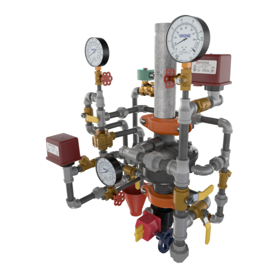
Viking supervised Double-Interlocked Electric/Pneumatic Release Preaction Systems
utilize the Viking G-2000P Valve. The small profile, lightweight, pilot operated Viking Model
G-2000P Valve comes complete as shown in Figure 8.
The system piping is pressurized with air or nitrogen to serve both as a means of supervising
the integrity of the piping network and as one portion of the system release operation. This
feature serves to prevent undetected leaks on the system piping network. If the system piping
or a sprinkler is damaged, the supervisory pressure is reduced and a "low air" supervisory
alarm is activated.
This pilot operated externally reset valve also includes an internal check diaphragm,
which eliminates the need for a separate check valve being installed in the system riser.
Double interlocked electric/pneumatic release preaction systems require the use of one 24
VDC normally closed (NC) electric solenoid and one pneumatic actuator. The electric sole-
noid is connected to a compatible release control panel and compatible detection devices.
The pneumatic actuator is controlled by the air pressure that is contained within the sprinkler
system piping. In fire conditions, both the solenoid and a sprinkler must open in order for the
G-2000P Valve to operate. When both the solenoid and pneumatic actuator open, the priming
water is relieved from the internal prime chamber assembly. The prime chamber assembly
collapses, and water passes through the G-2000P Valve and internal check diaphragm to the
system piping network. The entire sprinkler system fills with water.
Double interlock electric/pneumatic release preaction systems are commonly used in cold storage applications and other areas where
it is important to control accidental water discharge due to inadvertent damage to the sprinkler piping.
2. LISTING AND APPROVALS
cULus Listed: VLFT
FM Approved: Refrigerated Area Sprinkler Systems
3. TECHNICAL DATA
Specifications:
Pressure Rating: 250 PSI (17.2 Bar) Water Working Pressure
Factory Hydrostatically Tested to: 500 PSI (34.5 bar)
Friction Loss (Given in feet of Schedule 40 pipe based on Hazen & Williams formula C = 120):
Model G-2000P Valve: 8.5'
10" Section of Pipe: 1'
Water Supply Control Valve: 1.9'
Model G-2000P Valve C v Factor: 115.6
Valve Color: Black
Material Specifications:
Refer to Figure 11.
Ordering Information:
Available since 2010.
Part Number: G-2000P Double Interlock Electric/Pneumatic Preaction Riser Assembly: 16188-1 (Refer to Figure 8)
Accessories:
(Refer to Figure 9)
Drain Manifold: 16211
Model E-1 Accelerator: 08055
Model LD-1 Anti-Column Device: 14800
4. INSTALLATION:
A. General Installation Instructions
1. For proper operation and approval, the valve must be installed in the vertical position as trimmed from the factory. DO NOT
modify the factory assembled trim except as described in this technical data sheet.
2. A 10" section of pipe is provided with the G-2000P Double Interlock Electric/Pneumatic Preaction Riser Assembly. Prior to
valve maintenance, this section of pipe may be removed to provide clearance for lifting the cover from the body.
3. The G-2000P Valve must be installed in an area not subject to freezing temperatures or physical damage. If required, provide
Form No. F_011510
18.10.25
TECHNICAL DATA
P65
2" MODEL G-2000P
DOUBLE INTERLOCK PREACTION
WITH ELECTRIC/PNEUMATIC RELEASE
Q = C v
Q = Flow
C v = Flow Factor (GPM/1 PSI ∆P)
∆P = Pressure Loss through Valve
S = Specific Gravity of Fluid
Viking Technical Data may be found on
The Viking Corporation's Web site at
http://www.vikinggroupinc.com.
The Web site may include a more recent
edition of this Technical Data Page.
Replaces Form No. F_011510 Rev January 6, 2012
Page 1 of 12
√
∆P
S
(Added P65 Warning.)
Advertisement

Related Manuals for Viking G-2000P


Summary of Contents for Viking G-2000P
- Page 1 3. The G-2000P Valve must be installed in an area not subject to freezing temperatures or physical damage. If required, provide Form No.
- Page 2 2” MODEL G-2000P TECHNICAL DATA DOUBLE INTERLOCK PREACTION WITH ELECTRIC/PNEUMATIC RELEASE The Viking Corporation, 210 N Industrial Park Drive, Hastings MI 49058 Telephone: 269-945-9501 Technical Services: 877-384-5464 Fax: 269-818-1680 Email: techsvcs@vikingcorp.com Figure 1 - Air Supply Options Form No. F_011510...
- Page 3 1. Air Compressor Size Viking recommends tank-mounted air compressors for Double Interlock Electric/Pneumatic Release Preaction Systems. The pneumatic actuator requires at least 30 PSI (2.1 bar) of air pressure be established within the piping network for systems with water pressure up to 175 PSI (12.1 bar) and 50 PSI (3.45 bar) of air pressure for systems with water pressures up to 250 PSI (17.2 bar).
-
Page 4: Field Adjustments
2. Automatic air supplies must be regulated, restricted, and from a continuous source. A Viking Air Maintenance Device should be installed on each system equipped with a tank mounted compressor, plant air or nitrogen. For compressors with a capac- ity less than 5.5 ft... - Page 5 2” MODEL G-2000P TECHNICAL DATA DOUBLE INTERLOCK PREACTION WITH ELECTRIC/PNEUMATIC RELEASE The Viking Corporation, 210 N Industrial Park Drive, Hastings MI 49058 Telephone: 269-945-9501 Technical Services: 877-384-5464 Fax: 269-818-1680 Email: techsvcs@vikingcorp.com Figure 5 - Trim Components 6. Close the main drain valve.
-
Page 6: Operation
The closed pneumatic actuator and the normally closed solenoid valve prevent prime water from escaping the prime chamber of the G-2000P Valve. When prime water enters the prime chamber, the rolling diaphragm is pressurized, causing it to expand downward onto the water seat. - Page 7 With both the pneumatic actuator and solenoid valve open, prime water is drained from the prime chamber, causing the G-2000P Valve to open, filling the sprinkler piping with water. Water from the intermediate chamber of the G-2000P Valve pressurizes the sensing end of the PORV, causing the PORV to open. The open PORV prevents water pressure from building in the prime chamber should the solenoid or pneumatic actuator close.
-
Page 8: Maintenance
To Test Sprinkler System “Low Supervisory Air” Alarm: 1. To prevent operation of the G-2000P Valve and filling the system with water during the test, DO NOT operate the electric detection system during test. Consider closing the main water supply control valve. - Page 9 (4) toward the prime line and remove from the body. 2. Inspect and replace if necessary. 3. Inspect the seat. The seat should be clean and free of foreign material. If the seat is damaged, the G-2000P Valve must be replaced.
- Page 10 Page 10 of 12 2” MODEL G-2000P TECHNICAL DATA DOUBLE INTERLOCK PREACTION WITH ELECTRIC/PNEUMATIC RELEASE The Viking Corporation, 210 N Industrial Park Drive, Hastings MI 49058 Telephone: 269-945-9501 Technical Services: 877-384-5464 Fax: 269-818-1680 Email: techsvcs@vikingcorp.com Part Number 16188-1: Model G-2000P Valve G-2000P...
- Page 11 2” MODEL G-2000P TECHNICAL DATA DOUBLE INTERLOCK PREACTION WITH ELECTRIC/PNEUMATIC RELEASE The Viking Corporation, 210 N Industrial Park Drive, Hastings MI 49058 Telephone: 269-945-9501 Technical Services: 877-384-5464 Fax: 269-818-1680 Email: techsvcs@vikingcorp.com Figure 10 - Installation Dimensions Form No. F_011510 18.10.25...
- Page 12 2” MODEL G-2000P TECHNICAL DATA DOUBLE INTERLOCK PREACTION WITH ELECTRIC/PNEUMATIC RELEASE The Viking Corporation, 210 N Industrial Park Drive, Hastings MI 49058 Telephone: 269-945-9501 Technical Services: 877-384-5464 Fax: 269-818-1680 Email: techsvcs@vikingcorp.com Figure 11 - Model G-2000P Valve Components List/Replacement Parts Item No.