
Related Manuals for Stanley AC6359

Summary of Contents for Stanley AC6359
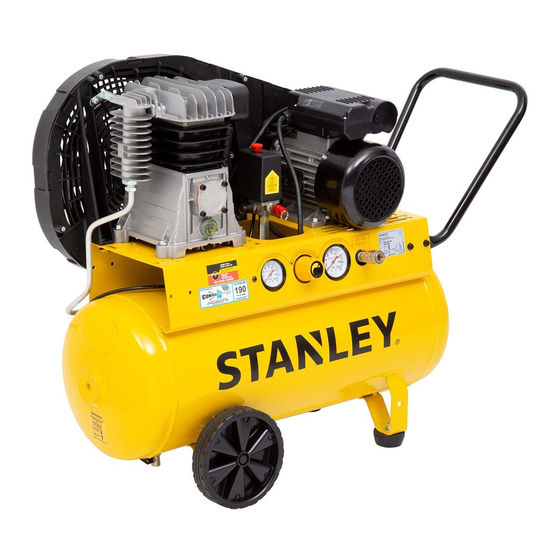
- Page 1 2.5HP 50LT Belt Drive Air Compressor For service, spare parts or product information, MODEL NO. please contact Smart Marketing Group Pty. Ltd. AC6359 AUST. 1300 660 457 N.Z. 0800 474 876 03400 06/16...
-
Page 2: Table Of Contents
CONTENTS SUGGESTED APPLICATIONS You may use most light duty air tools with this compressor. Some Section Page examples of light duty tools are: CLEANING Contents • Engine cleaning gun Suggested Applications • Sandblaster kit • Air blow gun Introduction • Abrasion kit TOOLS Warranty 3 - 4... -
Page 3: Introduction
INTRODUCTION How to claim under this warranty • Call customer service, phone number at the top. Dear Customer, • Ensure you have the following: Original purchase receipt, Model of Thank you for purchasing this compressor which has passed through compressor, Serial number of compressor. our extensive quality assurance processes. -
Page 4: Warranty
COMPLETE WARRANTY STATEMENT – COMPRESSOR GROUP As soon as you have purchased the compressor, we recommend that Cost of a loan compressor is not covered under this warranty. Loss of you check to make sure it is intact and that you read the operating income is not covered under this warranty. -
Page 5: General Safety Instructions
LUBRICATION OF COMPRESSOR WORK AREA Your compressor is oil filled. Do not tip to unpack or assemble. Check Work areas and benches should be kept tidy. Cluttered benches and the oil level to ensure the level is to the top of the red dot on the sight work areas can cause accidents. - Page 6 DO NOT ABUSE THE POWER CORD REMOVE ADJUSTING KEYS AND WRENCHES Never yank or pull on the power cord to disconnect it from the mains supply socket. Never carry or pull your air compressor by its power Form the habit of always checking to see that any adjusting keys or cord.
- Page 7 CHECK DAMAGED PARTS PERSONAL SAFETY Before using the air compressor it should be carefully checked to Clothing determine that it will operate properly and perform its intended Do not wear loose clothing, jewellery or anything that could get caught function. in moving machinery.
-
Page 8: Electrical Information
ELECTRICAL DATA IMPORTANT This air compressor is fitted with a sealed electrical connection plug that is compatible with the mains power supply for Australia / New Zealand and meets the requirements of Australian Standards. This air compressor must be connected to a supply voltage that is equal to that stated on the rating label. -
Page 9: Components And Controls
PIC. 1 COMPONENTS AND CONTROLS Pic. 1 Handle Motor reset button Belt guard Pressure switch On/Off button (Red button) Air filter Pump Sight glass Oil drain bolt 10. Motor/Pump Deck 11. Tank 12. Wheel 13. Tank pressure gauge - Small 14. -
Page 10: Operating Instructions
OPERATING INSTRUCTIONS PIC. 2 Unpacking Carefully unpack your air compressor. This air compressor is bulky and heavy, two (2) person lift required. Dispose of all packing material in an environmentally responsible manner. Assembly Your air compressor requires minor assembly before initial operation. Oil breather Check that you have all required components required for assembly and initial use. - Page 11 RUBBER STOPPER PIC. 5 To attach the rubber stoppers to the bracket located on the bottom of the tank; 1. Undo and remove the nut and star washer. 2. Push through the bracket and replace the star washer and nut. 3.
- Page 12 AIR FILTER PIC. 8 Air filter is factory fitted. To replace filter: 1. Carefully unscrew the screws inside the air filter. 2. Remove air filter. 3. Replace with new air filter. 4. Replace and tighten the screws to secure the air filter .
- Page 13 RUNNING IN YOUR NEW USING THE AIR COMPRESSOR AIR COMPRESSOR Before starting, run through this simple list: Before running in ensure that the following has been Oil level – CORRECT (top of red dot). completed: Please refer to diagram, Pic. 4, page 10. Drain tap –...
- Page 14 PIC. 10 The configuration of tools and accessories can be varied to suit your particular requirements. A basic recommended set up is shown in Pic.10 When you have finished using your air compressor follow these simple steps: 1. Turn your air compressor OFF, using the ON/OFF button.
- Page 15 ADJUSTING THE PRESSURE PIC. 11 On /Off button Pressure To adjust the outlet air pressure, use the orange coloured regulator switch knob and check the pressure on the outlet pressure gauge, Pic. 11. If the pressure needs to be lower, turn anti clockwise. If the pressure needs to be higher, turn clockwise.
- Page 16 DRAIN TAP PIC. 14 Pic. 14 Drain Tap Sealed After use open the drain tap to drain excess air and any moisture. The excess air will also help purge the moisture. Leave the drain tap open when air compressor is not in use, so any moisture can continue to drain To close and seal push lever up Right or left To open the drain tap pull the lever down to vertical.
- Page 17 BELT STRAIGHTNESS PIC. 16 Pic. 16 Belt straightness is paramount to a safe and reliable air compressor. The belt should always run in a straight line between the two (2) pulleys. If the belt is on an angle this could cause excessive strain and wear on components.
-
Page 18: Maintenance
MAINTENANCE PIC. 18 Daily Before use 1. Seal the tank drain tap, see Pic.14. 2. Check the oil level, see page 10, Pic. 4. 3. Check safety valve operation, see page 14, Pic. 12. 4. Check the belt tension, Pic 15, Page 16. Movement should be 10-15mm. -
Page 19: Parts Diagram
PARTS DIAGRAM Image may not match exactly. For reference only. Part Description SMG Part No. Part Description SMG Part No. Air Filter 95 AC6359AF 64-66 Rubber Stopper with Bolt & Nut 95 AC6359RS Cylinder Head 95 AC6359CH Safety Pressure Valve 95 AC6359SPV Drain Tap 95 AC6359DT... -
Page 20: Technical Information
TECHNICAL INFORMATION Specifications Air Compressor AC6359 Voltage 240V AC ~ 50Hz Motor Electric 2 ½ Hp Wattage 2200W No Load Speed 1400 RPM Free Air Delivery (FAD) 190 L per minute* Tank Size 50 L For any queries or assistance call Customer Service AUST.