Table of Contents
Advertisement
Quick Links
Unpacking
Thank you for buying the MSI
to make sure your motherboard box contains the following items. If something is
missing, contact your dealer as soon as possible.
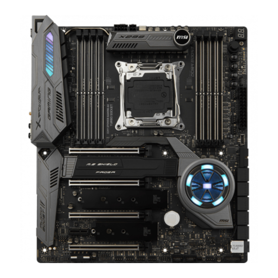
Motherboard
I/O Shield
Thermistor
Cable
SATA Cable x6
SATA Cable Labels
X299 XPOWER GAMING AC
®
Drivers & Utilities
Disc
M.2 Xpander-Z
SLI Bridge
Connector
Antenna x2
motherboard. Check
Motherboard User
Guide
Quick Guide
Case Badge
1 to 2 RGB LED Extension
Y Cable 80cm x1
3D X-MOUNTING
Screw Pillars
Unpacking
1
Advertisement
Table of Contents
Troubleshooting

Related Manuals for MSI X299 XPOWER GAMING AC


Summary of Contents for MSI X299 XPOWER GAMING AC
-
Page 1: Unpacking
Unpacking Thank you for buying the MSI X299 XPOWER GAMING AC motherboard. Check ® to make sure your motherboard box contains the following items. If something is missing, contact your dealer as soon as possible. Drivers & Utilities Motherboard User... -
Page 2: Safety Information
Safety Information y The components included in this package are prone to damage from electrostatic discharge (ESD). Please adhere to the following instructions to ensure successful computer assembly. y Ensure that all components are securely connected. Loose connections may cause the computer to not recognize a component or fail to start. -
Page 3: Quick Start
Quick Start Preparing Tools and Components Intel LGA 2066 CPU ® Thermal Paste CPU Fan DDR4 Memory Power Supply Unit Chassis SATA Hard Disk Drive Graphics Card SATA DVD Drive A Package of Screws Phillips Screwdriver Quick Start... -
Page 4: Installing A Processor
Installing a Processor https://youtu.be/ecdkLMmkya4 Quick Start... -
Page 5: Installing Ddr4 Memory
Installing DDR4 memory http://youtu.be/T03aDrJPyQs DIMMC1 Quick Start... -
Page 6: Connecting The Front Panel Header
Connecting the Front Panel Header http://youtu.be/DPELIdVNZUI HDD LED + Power LED + HDD LED - Power LED - Reset Switch Power Switch Reset Switch Power Switch JFP1 Reserved No Pin JFP1 HDD LED - HDD LED HDD LED + POWER LED - POWER LED POWER LED + Quick Start... -
Page 7: Installing The Motherboard
Installing the Motherboard Quick Start... -
Page 8: Installing Sata Drives
Installing SATA Drives http://youtu.be/RZsMpqxythc Quick Start... -
Page 9: Installing A Graphics Card
Installing a Graphics Card http://youtu.be/mG0GZpr9w_A Quick Start... -
Page 10: Connecting Peripheral Devices
Connecting Peripheral Devices Quick Start... -
Page 11: Connecting The Power Connectors
Connecting the Power Connectors http://youtu.be/gkDYyR_83I4 ATX_PWR1 CPU_PWR1 JPWR1 CPU_PWR2 Quick Start... -
Page 12: Power On
Power On Quick Start... -
Page 13: Table Of Contents
Contents Unpacking ......................1 Safety Information ....................2 Quick Start ......................3 Preparing Tools and Components ................3 Installing a Processor ..................... 4 Installing DDR4 memory ..................5 Connecting the Front Panel Header ............... 6 Installing the Motherboard ..................7 Installing SATA Drives..................... - Page 14 JUSB5: USB 3.1 Gen2 Type-C Connector ............. 47 CPU_FAN1, PUMP_FAN1, SYS_FAN1~4, EXS_FAN1~4: Fan Connectors .... 48 T_SEN1: Thermal Sensor Connector ..............48 JAUD1: Front Audio Connector ................49 JCI1: Chassis Intrusion Connector ............... 49 JTPM1: TPM Module Connector ................50 JBAT1: Clear CMOS (Reset BIOS) Jumper ............
- Page 15 LIVE UPDATE 6 ...................... 86 COMMAND CENTER ..................... 88 GAMING APP ......................92 X-BOOST ....................... 97 MYSTICLIGHT ......................99 MSI SMART TOOL ....................101 RAMDISK......................103 GAMING LAN MANAGER ..................104 DRAGON EYE ...................... 106 Nahimic 2 ......................107 XSplit Gamecaster V2 ..................111 SteelSeries Engine 3 ..................
-
Page 16: Specifications
Supports Intel Extreme Memory Profile (XMP) ® * For the latest information about memory, please visit http://www.msi.com ** Please refer the DIMM Slots section for more details. y 4x PCIe 3.0 x16 slots ƒ Support x16/x0/x16/x8, x8/x8/x16/x8 mode with the 44-lane CPU.*... - Page 17 Continued from previous page Intel X299 Chipset ® y 10x SATA 6Gb/s ports* y 3x M.2 slots (Key M)* ƒ M2_1, M2_2 slots support 2242/ 2260 /2280/ 22110 storage devices ˜ Supports up to PCIe 3.0 x4 and SATA 6Gb/s ƒ...
- Page 18 Continued from previous page y 1x Clear CMOS button y 1x BIOS FLSAHBACK+ button y 1x PS/2 keyboard/ mouse combo port y 2x USB 2.0 Type-A ports ƒ 1x BIOS FLASHBACK+ port y 6x USB 3.1 Gen1 Type-A ports Back Panel Connectors y 2x LAN (RJ45) ports y 1x USB 3.1 Gen2 Type-A port...
- Page 19 Continued from previous page y 1x GAME BOOST knob y 1x Power button Internal Buttons y 1x Reset button y 1x BCLK+/ Ratio+ button y 1x BCLK-/ Ratio- button Switches y 1x Multi-BIOS switch y 1x Clear CMOS jumper y 1x OC retry connector Jumper y 1x OC force enter BIOS connector y 1x Chassis Intrusion connector...
- Page 20 FAST BOOST y SUPER CHARGER y Nahimic Audio y XSplit Gamecaster V2 y SteelSeriesEngine 3 y WTFast y CPU-Z MSI GAMING y Intel Extreme Tuning Utility y Norton™ Internet Security Solution y Google Chrome™ ,Google Toolbar, Google Drive y TriDef ®...
- Page 21 Continued from previous page y Audio ƒ Audio Boost 4 ƒ Nahimic 2 y Network ƒ GAMING LAN with Gaming LAN Manager ƒ Dual LAN ƒ Intel WiFi y Storage ƒ Turbo U.2 ƒ Triple Turbo M.2 y Fan ƒ Pump Fan ƒ...
- Page 22 Continued from previous page y Performance ƒ Multi GPU – SLI Technology ƒ Multi GPU – CrossFire Technology ƒ DDR4 Boost ƒ GAME Boost ƒ OC Engine ƒ Lightning USB ƒ Front Lightning USB ƒ USB with Type A+C y Stability ƒ...
-
Page 23: Block Diagram
Block Diagram 2/ 4 Channel DDR4 Memory Processor Switch Switch 1x M.2 ASMEDIA ASM1061 PCI Express Bus 2x SATA 6Gb/s DMI 3.0 Switch PCIe x1 slot Wi-Fi / Bluetooth 2x M.2 Intel I211 8x SATA 6Gb/s Switch Intel I219 1x U.2 PCIE Bus X299 PCH ASMEDIA... -
Page 24: Rear I/O Panel
Rear I/O Panel WiFi antenna Audio Ports USB 3.1 Gen1 connectors PS/2 Clear CMOS BIOS USB 3.1 Gen2 Type-C USB 2.0 FLASHBACK+ Optical S/PDIF-Out button USB 3.1 Gen1 USB 2.0/ USB 3.1 Gen2 Type-A BIOS FLASHBACK+ port y Clear CMOS button - Power off your computer. Press and hold the Clear CMOS button for about 5-10 seconds to reset BIOS to default values. -
Page 25: Realtek Hd Audio Manager
Realtek HD Audio Manager After installing the Realtek HD Audio driver, the Realtek HD Audio Manager icon will appear in the system tray. Double click on the icon to launch. Device Selection Advanced Settings Jack Status Application Enhancement Connector Main Volume Settings Profiles y Device Selection - allows you to select a audio output source to change the related... - Page 26 Audio jacks to headphone and microphone diagram Audio jacks to stereo speakers diagram AUDIO INPUT Audio jacks to 7.1-channel speakers diagram AUDIO INPUT Rear Front Side Center/ Subwoofer Rear I/O Panel...
-
Page 27: Installing Antennas
Installing Antennas 1. Screw the antennas tight to the WiFi antenna connectors as shown. 2. Place the antennas as high as possible. Rear I/O Panel... -
Page 28: Overview Of Components
Overview of Components DIMMA2 DIMMD1 DIMMD2 DIMMA1 DIMMC1 DIMMB2 CPU_PWR1 DIMMC2 DIMMB1 CPU_PWR2 CPU Socket CPU_FAN1 POWER RESET PLUS VRAID1 MINUS PUMP_FAN1 ATX_PWR1 SYS_FAN4 EXS_FAN4 JUSB5 SYS_FAN1 PCI_E1 JUSB4 M2_1 SATA▼1▲2 PCI_E2 SATA▼3▲4 M2_2 SATA▼5▲6 PCI_E3 SATA▼7▲8 M2_3 PCI_E4 SATA▼9▲10 U2_1 PCI_E5 JBAT1... - Page 29 Component Contents Port Name Port Type Page BIOS_SW1 Multi-BIOS Switch CPU_FAN1, PUMP_FAN1, Fan Connectors SYS_FAN1~4, EXS_FAN1~4 CPU_PWR1~2, ATX_PWR1, Power Connectors JPWR1 CPU Socket LGA2066 CPU Socket DIMMA1~DIMMD2 DIMM Slots JAUD1 Front Audio Connector JBAT1 Clear CMOS (Reset BIOS) Jumper JCI1 Chassis Intrusion Connector JFP1, JFP2 Front Panel Connectors...
-
Page 30: Cpu Socket
Always unplug the power cord from the power outlet before installing or removing the CPU. Please retain the CPU protective cap after installing the processor. MSI will deal with Return Merchandise Authorization (RMA) requests if only the motherboard comes with the protective cap on the CPU socket. -
Page 31: Dimm Slots
DIMM Slots S/K LED : S/K LED indicates that the installed CPU supports either 4-channels or 2-channels memory architecture. Red = 8 DIMMs support (4-channels architecture CPU) White = 4 DIMMs support (2-channels architecture CPU) B1B2A1A2 C2C1D2D1 Memory module installation recommendation (4-Channels architecture CPU ) Intel Core X-series CPU 1 DIMM 2 DIMMs... - Page 32 DIMMD1 DIMMA1 DIMMA1 DIMMC1 DIMMC1 DIMMB1 DIMMB1 DIMMA2 DIMMD1 DIMMA2 DIMMD1 DIMMA1 DIMMA1 DIMMD2 DIMMB2 DIMMC1 DIMMC1 DIMMB1 DIMMB1 DIMMC2 DIMMC2 Important Always insert a memory module in the DIMMC1 slot first. To ensure system stability for Dual/ Triple/ Quad channel mode, memory modules must be of the same type, number and density.
- Page 33 Memory module installation recommendation (2-Channels architecture CPU ) Intel Core X-series CPU 1 DIMM 2 DIMMs Supports 2-channels memory architecture 3 DIMMs 4 DIMMs DIMMB1, B2, A1 and A2 are un-available DIMMD1 DIMMC1 DIMMC1 DIMMD1 DIMMD1 DIMMD2 DIMMC1 DIMMC1 DIMMC2 DIMMC2 Overview of Components...
-
Page 34: Pci_E1~6: Pcie Expansion Slots
PCI_E1~6: PCIe Expansion Slots PCI_E1: PCIe 3.0 x16 (CPU lanes) PCI_E2: PCIe 3.0 x8 (CPU lanes) PCI_E3: PCIe 3.0 x16 (CPU lanes) PCI_E4: PCIe 3.0 x1 (PCH lanes) PCI_E5: PCIe 3.0 x8 (CPU lanes) PCIe and M2_3 slots bandwidth table for 44-lane CPU Graphics Card Single... - Page 35 PCI_E3 For 44-lane CPU Important If you install a large and heavy graphics card, you need to use a tool such as MSI Gaming Series Graphics Card Bolster to support its weight and to prevent deformation of the slot. PCI_E1...
- Page 36 Important For a single PCIe x16 expansion card installation with optimum performance, using the PCI_E1 slot is recommended. When adding or removing expansion cards, always turn off the power supply and unplug the power supply power cable from the power outlet. Read the expansion card’...
-
Page 37: U2_1: U.2 Connector
U2_1: U.2 Connector This connector is a U.2 interface port. Each connector can connect to one PCIe 3.0 x4 NVMe storage device. Video Demonstration Watch the video to learn how to Install U.2 SSD. http://youtu.be/KgFvKDxymvw Installing U.2 SSD 1. Connect the U.2 cable to the U.2 connector on the motherboard. -
Page 38: M2_1~3: M.2 Slots (Key M)
M2_1~3: M.2 Slots (Key M) Important Intel RST only supports PCIe M.2 SSD with UEFI ROM. ® Intel Optane™ Memory Ready for M2_1, M2_2 slots. ® M2_3 slot only supports PCIe 3.0 interface. M2_1 Video Demonstration M2_2 Watch the video to learn how to Install M.2 M2_3 module. - Page 39 Using M.2 SHIELD FROZR This motherboard has M.2 SHIELD FROZR on the M2_1 slot for heat dissipation from the M.2 module. Before installing the M.2 module for the first time, you need to: 1. Slide the M.2 SHIELD FROZR lock toward the back panel. 2.
-
Page 40: Installing The M.2 Xpander-Z
Installing the M.2 Xpander-Z The M.2 Xpander-Z card provide two M.2 Key-M slots. To install the M.2 Xpander-Z card: 1. Remove the screws from the mounting poles. 2. Lift the M.2 Shields and remove the protective films and the round rubbers from the thermal pads. -
Page 41: Sata1~10: Sata 6Gb/S Connectors
SATA1~10: SATA 6Gb/s Connectors These connectors are SATA 6Gb/s interface ports. Each connector can connect to one SATA device. SATA2 SATA1 SATA4 SATA3 SATA6 SATA5 SATA8 SATA7 SATA10 SATA9 Important Please do not fold the SATA cable at a 90-degree angle. Data loss may result during transmission otherwise. -
Page 42: Jfp1, Jfp2: Front Panel Connectors
M.2 slots with examples of various combination possibilities 1xM.2 PCIe SSD + 10xSATA HDDs 2xM.2 PCIe SSDs + 6xSATA HDDs M.2 PCIe M.2 PCIe M.2 PCIe 1xM.2 PCIe SSD + 1xM.2 SATA SSD 2xM.2 PCIe SSDs + 4xSATA HDDs + + 9xSATA HDDs 1xPCI_E4 Device M.2 PCIe... -
Page 43: Oc1: Game Boost Knob
OC1: GAME BOOST Knob This knob allows you to manually select a stage from number 0 (default) to number 11 (extreme) for overclocking the processor. The processor’ s voltage and frequency will be automatically adjusted after you power on your computer. GAME BOOST knob Using GAME BOOST Knob To setup the GAME BOOST knob, take the following steps:... -
Page 44: Oc_Rt1: Oc Retry Jumper
You can also control the GAME BOOST function in BIOS Setup or with MSI COMMAND CENTER software. In order to optimize performance and improve system stability, when you activate the GAME BOOST function, please leave the settings in the BIOS > OC menu unchanged. -
Page 45: Cpu_Pwr1~2, Atx_Pwr1, Jpwr1: Power Connectors
CPU_PWR1~2, ATX_PWR1, JPWR1: Power Connectors These connectors allow you to connect an ATX power supply. CPU_PWR1 Ground +12V Ground +12V Ground +12V Ground +12V CPU_PWR2 Ground +12V Ground +12V +3.3V +3.3V +3.3V -12V Ground Ground PS-ON# Ground Ground Ground ATX_PWR1 Ground Ground PWR OK... -
Page 46: Jusb1~2: Usb 2.0 Connectors
JUSB1~2: USB 2.0 Connectors These connectors allow you to connect USB 2.0 ports on the front panel. USB0- USB1- USB0+ USB1+ Ground Ground No Pin Important Note that the VCC and Ground pins must be connected correctly to avoid possible damage. -
Page 47: Jusb5: Usb 3.1 Gen2 Type-C Connector
However, when you boot the computer into Windows ® you will need to install the MSI SUPER CHARGER application to turn ON/OFF the ®... -
Page 48: Cpu_Fan1, Pump_Fan1, Sys_Fan1~4, Exs_Fan1~4: Fan Connectors
CPU_FAN1, PUMP_FAN1, SYS_FAN1~4, EXS_FAN1~4: Fan Connectors Fan connectors can be classified as PWM (Pulse Width Modulation) Mode or DC Mode. PWM Mode fan connectors provide constant 12V output and adjust fan speed with speed control signal. DC Mode fan connectors control fan speed by changing voltage. This motherboard can automatically detect PWM and DC mode. -
Page 49: Jaud1: Front Audio Connector
JAUD1: Front Audio Connector This connector allows you to connect audio jacks on the front panel. MIC L Ground MIC R Head Phone R MIC Detection SENSE_SEND No Pin Head Phone L Head Phone Detection JCI1: Chassis Intrusion Connector This connector allows you to connect the chassis intrusion switch cable. Normal Trigger the chassis intrusion event... -
Page 50: Jtpm1: Tpm Module Connector
JTPM1: TPM Module Connector This connector is for TPM (Trusted Platform Module). Please refer to the TPM security platform manual for more details and usages. LPC Clock 3V Standby power LPC Reset 3.3V Power LPC address & data pin0 Serial IRQ LPC address &... -
Page 51: Bios_Sw1: Multi-Bios Switch
When BIOS updating fails or causes the computer non-bootable, you can recover the failed BIOS by the steps below. Before recovering, please download the latest BIOS file that matches your motherboard model from MSI website. And then save the BIOS file to the root of the USB flash drive. -
Page 52: Power1, Reset1: Power Button, Reset Button
POWER1, RESET1: Power Button, Reset Button The Power / Reset button allows you to power on / reset the computer. Power button Reset button Plus, Minus buttons: BCLK-Ratio buttons You can use these buttons to increase or decrease the CPU BCLK/ Ratio. BCLK+ BCLK- / Ratio+... -
Page 53: Vraid1: Virtual Raid On Cpu Connector
Always turn off the power supply and unplug the power cord from the power outlet before installing or removing the RGB LED strip. Please use MSI’ s software to control the extended LED strip. Overview of Components... -
Page 54: Onboard Leds
Onboard LEDs EZ Debug LED These LEDs indicate the debug status of the motherboard. CPU - indicates CPU is not detected or fail. DRAM - indicates DRAM is not detected or fail. VGA - indicates GPU is not detected or fail. BOOT - indicates the booting device is not detected or fail. -
Page 55: Fan Leds
Fan LEDs These LEDs indicate the fan control mode. CPU_FAN1 LED LED color Fan control mode PUMP_FAN1 LED PWM mode SYS_FAN4 LED Green DC mode EXS_FAN4 LED SYS_FAN1 LED EXS_FAN1 LED EXS_FAN2 LED EXS_FAN3 LED SYS_FAN2 LED SYS_FAN3 LED Fan Speed Indicators There are a fan speed indicators on the chipset heatsink and backplane. -
Page 56: Debug Code Led
Debug Code LED The Debug Code LED displays progress and error codes during and after POST. Refer to the Debug Code LED table for details. Debug Code LED Hexadecimal Character Table Hexadecimal 0 1 2 3 4 5 6 7 8 9 A B C D E F Debug Code LED display Boot Phases... - Page 57 DXE Progress Codes Memory initialization. Memory presence detection DXE Core is started Memory initialization. Programming NVRAM initialization memory timing information Installation of the PCH Runtime Services Memory initialization. Configuring CPU DXE initialization is started memory CPU DXE initialization (CPU module Memory initialization (other) 64 - 67 specific)
-
Page 58: Acpi States Codes
Setup Verifying Password S3 Resume PPI not Found Start of Setup S3 Resume Boot Script Error Setup Input Wait S3 OS Wake Error Ready To Boot event EC - EF Reserved for future AMI error codes Legacy Boot event Recovery Progress Codes Exit Boot Services event Recovery condition triggered by firmware Runtime Set Virtual Address MAP Begin... -
Page 59: Updating Led Firmware
Updating the LED firmware can help improve lighting effect. To update LED firmware: 1. Install and launch MSI LIVE UPDATE 6. 2. Select BIOS Update. 3. Click on Scan button. If the LED firmware needs to be updated, the version of the firmware will appear in the list. -
Page 60: Bios Setup
Press Delete key, when the Press DEL key to enter Setup Menu, F11 to enter Boot Menu message appears on the screen during the boot process. y Use MSI FAST BOOT application. Click on GO2BIOS button and choose OK. The system will reboot and enter BIOS setup directly. -
Page 61: Resetting Bios
Updating BIOS Updating BIOS with M-FLASH Before updating: Please download the latest BIOS file that matches your motherboard model from MSI website. And then save the BIOS file into the USB flash drive. Updating BIOS: 1. Press Del key to enter the BIOS Setup during POST. - Page 62 Before updating: Please download the latest BIOS file that matches your motherboard model from MSI ® website and rename the BIOS file to MSI.ROM. And then, save the MSI.ROM file to the root of USB flash drive. Important Only the FAT32 format USB flash drive supports updating BIOS by BIOS FLASHBACK+.
-
Page 63: Ez Mode
EZ Mode At EZ mode, it provides the basic system information and allows you to configure the basic setting. To configure the advanced BIOS settings, please enter the Advanced Mode by pressing the Setup Mode switch or F7 function key. XMP switch Setup Mode switch Screenshot... - Page 64 y Information display - click on the CPU, Memory, Storage, Fan Info and Help buttons on left side to display related information. y Function buttons - enable or disable the LAN Option ROM, M.2/Optane Genie, Hardcore Mode, AHCI, RAID, CPU Fan Fail Warning Control and BIOS Log Review by clicking on their respective button.
-
Page 65: Advanced Mode
Advanced Mode Press Setup Mode switch or F7 function key can switch between EZ Mode and Advanced Mode in BIOS setup. XMP switch Setup Mode switch Screenshot Search Language System information GAME BOOST switch Boot device priority bar BIOS menu BIOS menu selection selection... -
Page 66: Settings
SETTINGS System Status f System Date Sets the system date. Use tab key to switch between date elements. The format is <day> <month> <date> <year>. <day> Day of the week, from Sun to Sat, determined by BIOS. Read-only. <month> The month from Jan. through Dec. <date>... - Page 67 fPEGX - Max Link Speed [Auto] Sets PCI Express protocol of PCIe x16 slots for matching different installed devices. [Auto] This item will be configured automatically by BIOS. [Gen1] Enables PCIe Gen1 support only. [Gen2] Enables PCIe Gen2 support only. [Gen3] Enables PCIe Gen3 support only.
- Page 68 fIpv4 PXE Support [Enabled] When Enabled, the system UEFI network stack will support Ipv4 protocol. This item will appear when Network Stack is enabled. [Enabled] Enables the Ipv4 PXE boot support. [Disabled] Disables the Ipv4 PXE boot support. fIpv6 PXE Support [Enabled] When Enabled, the system UEFI network stack will support Ipv6 protocol.
- Page 69 Disables this function. fMSI Fast Boot [Disabled] MSI Fast Boot is the fastest way to boot the system. It will disable more devices to speed up system boot time which is faster than the boot time of Fast Boot. [Enabled] Enables the MSI Fast Boot function to speed up booting time.
- Page 70 Boot [Enabled] Enables or disables the fast boot feature for Windows 10. This item will only be available when MSI Fast Boot is disabled. [Enabled] Enables the Fast Boot configuration to accelerate system boot time. [Disabled] Disables the Fast Boot configuration.
- Page 71 fResume By PCI-E Device [Disabled] Enables or disables the wake up function of installed PCI-E expansion cards, integrated LAN controllers or USB devices which are supported by third party integrated chips. [Enabled] Enables the system to be awakened from the power saving modes when activity or input signal of PCIe device is detected.
-
Page 72: Boot
Boot Sets the sequence of system boot devices. f Full Screen Logo Display [Enabled] Enables or disables to show the full screen logo while system POST. [Enabled] Shows the logo in full screen. [Disabled] Shows the POST messages. f GO2BIOS [Disabled] Allows system to enter BIOS setup directly by pressing the Power button for 4 sec pon bootup. -
Page 73: Security
Security f Administrator Password Sets administrator password for system security. User has full rights to change the BIOS items with administrator password. After setting the administrator password, the state of this item will show Installed. f User Password Sets User Password for system security. User has limited rights to change the BIOS items with user password. -
Page 74: Save & Exit
Save & Exit f Discard Changes and Exit Exit BIOS setup without saving any change. f Save Changes and Reboot Save all changes and reboot the system. f Save Changes Save current changes. f Discard Changes Discard all changes and restore to the previous values. f Restore Defaults Restore or load all default values. - Page 75 Important Overclocking your PC manually is only recommended for advanced users. Overclocking is not guaranteed, and if done improperly, it could void your warranty or severely damage your hardware. If you are unfamiliar with overclocking, we advise you to use GAME BOOST function for easy overclocking.
- Page 76 f CPU Ratio Mode [Dynamic Mode]* Selects the CPU Ratio operating mode. This item will appear when you set the CPU ratio manually. [Fixed Mode] Fixes the CPU ratio. [Dynamic Mode] CPU ratio will be changed dynamically according to the CPU loading.
- Page 77 f CPU Base Clock Apply Mode [Auto]* Sets the applying mode for adjusted CPU base clock. [Auto] This setting will be configured automatically by BIOS. [Next Boot] CPU will run the adjusted CPU base clock at next boot. [Immediate] CPU runs the adjusted CPU base clock immediately. f Direct OC Button [Enabled] Enables or disables the base clock buttons for real time overclocking.
- Page 78 fSRC Clock Amplitude [Auto] Sets the value for SRC clock Amplitude. fSATA Clock Amplitude [Auto] Sets the value for SATA clock Amplitude. fBCLK Slew Rate [Auto] Sets the value for BCLK Slew Rate for overclocking. The value might vary depending on the actual overclocking scenario. fBCLK ORT Duration [Auto] Sets the value for BCLK ORT duration for overclocking.
- Page 79 f VCCIN Voltage [Auto] Sets the CPU input voltage. The CPU input voltage is the CPU power source that is shared with components of the CPU. f CPU Voltages control [Auto] These options allows you to set the voltages related to CPU. If set to Auto, BIOS will set these voltages automatically or you can set it manually.
- Page 80 fLimit CPUID Maximum [Disabled] Enables or disables the extended CPUID value. [Enabled] BIOS limits the maximum CPUID input value to circumvent boot problems with older operating system that do not support the processor with extended CPUID value. [Disabled] Use the actual maximum CPUID input value. fIntel Virtualization Tech [Enabled] Enables or disables Intel Virtualization technology.
- Page 81 fC1E Support [Disabled] Enables or disables the C1E function for power-saving in halt state. This item appears when Intel C-State is enabled. [Enabled] Enables C1E function to reduce the CPU frequency and voltage for power-saving in halt state. [Disabled] Disables this function. fPackage C State Limit [Auto] This item allows you to select a CPU C-state level for power-saving when system is idle.
-
Page 82: M-Flash
M-FLASH provides the way to update BIOS with a USB flash drive. Please down-load the latest BIOS file that matches your motherboard model from MSI website, save the BIOS file into your USB flash drive. And then follow the steps below to update BIOS. -
Page 83: Oc Profile
OC PROFILE f Overclocking Profile 1/ 2/ 3/ 4/ 5/ 6 Overclocking Profile 1/ 2/ 3/ 4/ 5/ 6 management. Press <Enter> to enter the sub- menu. fSet Name for Overclocking Profile 1/ 2/ 3/ 4/ 5/ 6 Name the current overclocking profile. fSave Overclocking Profile 1/ 2/ 3/ 4/ 5/ 6 Save the current overclocking profile. -
Page 84: Software Description
7. Follow the instructions on the screen to install Windows ® Installing Drivers 1. Start up your computer in Windows ® 2. Insert MSI Driver Disc into your optical drive. ® 3. The installer will automatically appear and it will find and list all necessary drivers. -
Page 85: App Manager
Motherboard Information - shows the model name of motherboard. y Total Install/ Update - click on this tab to update/ install all the applications. Important Please note that, once you uninstall the APP MANAGER, all the MSI applications and software will be uninstalled simultaneously. Software Description... -
Page 86: Live Update 6
LIVE UPDATE 6 LIVE UPDATE 6 is an application for the MSI system to scan and download the latest ® drivers, BIOS and utilities. With LIVE UPDATE 6, you don’ t need to search the drivers on websites, and don’ t need to know the models of motherboard and graphics cards. - Page 87 1. Select the Live Update tab. 2. Choose Automatic scan, system will automatically scan all the items and search for the latest update files. Or you can choose Manual scan and select the items you wish to scan. 3. Click the Scan button at the bottom. It may take several moments to complete the process.
-
Page 88: Command Center
COMMAND CENTER COMMAND CENTER is an user-friendly software and exclusively developed by MSI, helping users to adjust system settings and monitor status under OS. With the help of COMMAND CENTER, making it possible to achieve easier and efficient monitoring process and adjustments than that under BIOS. In addition, the COMMAND CENTER can be a server for mobile remote control application. - Page 89 CPU Fan CPU Fan control panel provides Smart mode and Manual Mode. You can switch the control mode by clicking the Smart Mode and Manual Mode buttons on the top of the CPU Fan control panel. y Manual Mode - allows you to manually control the CPU fan speed by percentage.
- Page 90 GAME BOOST GAME BOOST has 8 overclocking stages for you to overclock your computer. COMMAND CENTER provides the software interface instead of GAME BOOST knob on the motherboard. You can click on the center button to switch GAME BOOST control between software (SW) and hardware (HW) .
- Page 91 7. Find the IP address on the SoftAP Management Setting area, and enter the IP address on your MSI COMMAND CENTER APP to link your system. ® 8. Press Refresh on the MSI COMMAND CENTER APP to verify that monitoring and ® OC functions are working properly.
-
Page 92: Gaming App
3. Connect your android device and motherboard to the same local area network. 4. Run MSI GAMING APP APP on your android device. ® 5. Press the Remote Control Setting icon on the MSI GAMING APP APP to find the ® paired device Name you set in the Remote Control Setting panel. - Page 93 OSD Setting Panel Use the OSD setting panel to specify information within on-screen display (OSD). y Apply Button - applies above settings to OSD. Eye Rest Eye Rest allows you to optimize the display on your monitor. y EyeRest - reduces blue-light of your LED backlit screen, in order to protect your eyes.
- Page 94 VR Ready It will optimize the performance of your system to ensure everything is VR Ready. VR ON/ OFF Applications y VR ON/ OFF -enables or disables VR settings. y Applications - appears when you turn on the VR support. It allows you to close some applications to optimize the system for better VR experience.
- Page 95 ƒ Login Keys - provides hotkey login function. ƒ MSI Smart Keys - allows you to define hotkeys for MSI Smart Keys. y Hotkey Manager - allows you to create, edit and delete hotkeys. y Current Hotkeys - shows all existing hotkeys.
- Page 96 Mouse Master Mouse Master provides mouse macro function. You can also use it to change DPI of your mouse. DPI Setting Delay Time Default Button Macro Hot Key DPI Hot Key Mouse Action Action List Test Area Edit Buttons Clear Button Load Button Save Button y Delay Time - allows you to apply a delay time in mouse macro.
-
Page 97: X-Boost
X-BOOST The MSI X-BOOST allows you to select the system performance mode to meet your current system environment or support faster storage access speed for your external storage or memory cards. Easy In Easy page, you can select one system performance mode to meet the current system environment. - Page 98 OPTANE BOOST - supports faster access speed of Intel Optane memory (require a reboot). Important Please note that you can only select one mode at a time from Easy or Advance page as MSI X-BOOST function. The improved transfer rate/ access speed will vary with the USB/ storage device. Software Description...
-
Page 99: Mysticlight
MYSTICLIGHT MYSTICLIGHT is an application allows you to control LED lights of MSI products. Main Screen The Main screen is used to configure what devices need to be synchronized and LED light effect options. Sync Devices ON/ OFF All LED... - Page 100 Motherboard Screen The motherboard screen is used to configure the LED light effect of the motherboard. Sync All Return Button Motherboard ON/ OFF All LED Name Profile Live Preview LED Area Light Effect Apply Button Options Save Button Note: The motherboard picture and name may vary according to different models. y Return Button - returns to the main screen.
-
Page 101: Msi Smart Tool
MSI SMART TOOL MSI SMART TOOL is a convenient tool that can help you to create your Windows installation USB flash drive with USB 3.0 drivers, and it can also create a software RAID. Main menu After installing and activating MSI SMART TOOL, it will display a main menu for you to choose Win7 Smart Tool or Software RAID. - Page 102 SOFTWARE RAID This utility allows you to create a software RAID in Windows system. To create a software RAID: 1. Use checkboxs to select the disks you want included in your RAID. 2. Choose Speed Up or Backup for RAID type. y Speed Up = RAID0 y Backup = RAID1 3.
-
Page 103: Ramdisk
RAMDISK RAMDISK creates a virtual RAM drive using the available memory in your computer, the performance of the RAMDISK is faster than an SSD and hard drive. RAMDISK allows you to store any temporary information on it. Furthermore, using the RAMDISK will extend your SSD’... -
Page 104: Gaming Lan Manager
GAMING LAN MANAGER GAMING LAN MANAGER is an utility for traffic shaping for the Windows 10. It can keep your internet fast during heavy upload/ download and improve your ping for online games. If your motherboard has a Wi-Fi module, GAMING LAN MANAGER provides virtual access point function for traffic shaping for your mobile devices. - Page 105 Speed Testing The speed testing is used to optimize bandwidth usage. To test the Upload and Down- load speed, please follow the steps below: 1. Click the Network Test block in GAMING LAN MANAGER. 2. Click Test Network Speed button. The test takes several minutes to test your network speed.
-
Page 106: Dragon Eye
DRAGON EYE DRAGON EYE allows you to watch game guides, tutorials, live match or tournament stream while gaming. In game, you can use hotkeys to control/adjust the settings of DRAGON EYE. Size Settings Position Settings On / Off Switch Help Transparency Settings Video List Hotkeys Information... -
Page 107: Nahimic 2
HD Audio Recorder2 and Sound Tracker. Installation and Update Nahimic 2 is included in the audio driver. If you need to install it or update it, please use the Driver Disc with your motherboard or download the driver from MSI’ s official website. Audio Tab From this tab, you can access all of Nahimic 2’... - Page 108 ƒ Treble Enhancer - Increases the energy in high frequencies up to +12 dB. ƒ Smart Loudness - maintains a constant volume for all elements of the audio experience to making them all sound softer, balanced or louder. ƒ Voice Clarity - boosts the speech in movies, video games and incoming communication from +0 through +12 dB (0 to 100%).
- Page 109 y Display & Volume - displays the type of audio recording device currently being used as input, as well as its current volume. ƒ Mute - mutes the current device. ƒ Device properties - allows you to boost the volume and modify the left/ right balance of microphone.
- Page 110 y Control Page - by clicking the arrow button, you can access the control page. ƒ Audio Launchpad ON/OFF - switches the Audio Launchpad on or off. ƒ HD Audio Recorder 2 - The HD Audio Recorder 2 is, by default, automatically launched when a XSplit Gamecaster 2 recording session is detected.
-
Page 111: Xsplit Gamecaster V2
Login button. Important When starting XSplit Gamecaster V2 on select MSI gaming laptops, all-in ones or on ® machines that contain select MSI motherboards or graphics cards, you will receive ®... - Page 112 Learning stream and record Refer to the Start page of XSplit Gamecaster V2 to learn how to stream and record your gameplay. Tool Tip When you click the question mark next to a feature name on the panel, a tooltip will show, describing the particular function of that item.
- Page 113 5. Share Button - If you authorize your Facebook, Twitter, and/or Google+ accounts, you can quickly share your stream URL and status update within the overlay. 6. Annotations - This feature of XSplit Gamecaster V2 allows you to draw directly onto your game play.
- Page 114 see your desired device in the list, please make sure that it is detected and it is not disabled in your recording devices list in the Windows Sound Menu (Start > Control ® Panel > Sound > Recording). y Camera Settings - In this region, you can select your desired camera. What is shown in the list depends on the cameras you have connected to your PC (Control Panel >...
-
Page 115: Steelseries Engine 3
SteelSeries Engine 3 SteelSeries Engine 3 is a unified platform built to support all of SteelSeries products. It can deploy your saved device settings automatically when switching between your favorite games or applications. After installation the SteelSeries Engine background processes will start and the interface will open automatically. - Page 116 Configuring Your Devices You can custom configurations for SteelSeries devices in their Configuration Windows. The top left displays the name of the configuration you are viewing, the body features widgets for customizing various functions of the device, and at the bottom are Save/ Revert buttons, a Live Preview toggle, and a button to open/close the collapsible Configuration List Panel.
-
Page 117: Intel ® Extreme Tuning Utility
Intel Extreme Tuning Utility ® Intel Extreme Tuning Utility (Intel XTU) is a simple overclocking software for you to ® tune, test and monitor your system. Tuning Controls Views Settings Help System Navigation Table System System Monitors Graphs y Views Settings Help ƒ... -
Page 118: Cpu-Z
CPU-Z CPU-Z is an utility that gathers information on some of the main devices of your system. y CPU Tab - shows processor name, code name, package, specification, instructions sets, core speed and cache levels. y Caches Tab - shows extended information related to the cache capabilities. y Mainboard Tab - shows motherboard manufacturer, model name, chipset, BIOS version and graphic interface. -
Page 119: Tridef Vr
TriDef VR With TriDef VR you can play your favorite PC games on a huge 3D screen inside your virtual reality headset. It is compatible with the Oculus Rift and HTC Vive. After installation, please ensure that your VR headset is set up and working correctly, then double-click TriDef VR Games on the Desktop, or from: Start >... - Page 120 Games Tab The first tab you’ ll see on the main window is the Games tab. As mentioned, apps or games launched from the desktop will appear in 2D on the virtual screen. However, if you launch a supported game from the Games tab, it will be displayed on the virtual screen in stereoscopic 3D! The first time you launch TriDef VR, the application will scan your PC and automatically add supported games to the list.
- Page 121 Settings Popup Look at the Settings item for 1 second to display the Settings popup. This popup window appears in front of the virtual screen. Use your mouse to adjust the slider values. y Screen Settings - adjust the virtual screen’ s size, distance and curvature. y Game Settings - adjust 3D settings for that game.
-
Page 122: Tridef Smartcam
TriDef SmartCam Use TriDef SmartCam to replace or SmartBlur your background in video chat applications or to remove your background in XSplit. Just select TriDef SmartCam wherever you see a list of cameras or choose your webcam application. The following description uses XSplit Gamecaster for an example. TriDef SmartCam for XSplit Gamecaster After installation TriDef SmartCam is integrated into XSplit Gamecaster version 2.5 and newer. -
Page 123: Raid Configuration
RAID Configuration Below are the different types of a RAID. RAID 0 breaks the data into blocks which are written to separate hard drives. Spreading the hard drive I/O load across independent channels greatly improves I/O performance. RAID 1 provides data redundancy by mirroring data between the hard drives and provides enhanced read performance. - Page 124 Creating s RAID Volume 1. Select option Create RAID Volume and press Enter key. The following screen appears. CREATE VOLUME MENU Name : Volume0 RAID Level : RAID1(Mirror) Disks : Select Disks Strip Size : N / A Capacity : XXX.X GB Sync : N / A...
- Page 125 Removing a RAID Volume Here you can delete the RAID volume, but please be noted that all data on RAID drives will be lost. Important If your system currently boots to RAID and you delete the RAID volume in the IRST Option ROM, your system will become unbootable.
-
Page 126: Degraded Raid Array
Important You will lose all data on the RAID drives and any internal RAID structures when you perform this operation. Possible reasons to Reset Disks to Non-RAID could include issues such as incompatible RAID configurations or a failed volume or failed disk. Recovery Volume Options Select option Recovery Volume Options from the main menu screen and press Enter to change recovery volume mode. - Page 127 2. Reconnect the hard drive. 3. Reboot to Windows ; the rebuild will occur automatically. ® Failed Hard Drive Member 1. Power off. 2. Replace the failed hard drive with a new one that is of equal or greater capacity. 3.
-
Page 128: M.2 Pcie Ssd Raid
RAID 0 volume. During windows setup, the RAID driver may be required and you can find the RAID driver in MSI Driver Disc. You can use MSI SMART TOOL to build the Windows 7/ 8.1/ 10 installation drive that ®... - Page 129 12. Select Create RAID Volume and press Enter key..\Intel(R) Rapid Storage Technology\ Create RAID Volume Create RAID Volume Name: Volume1 RAID Level: [RAID0(Stripe)] Select Disks: PCIe, XXXXX XXXXXXXX-XXXX, XXXGB PCIe, XXXXX XXXXXXXX-XXXX, XXXGB Strip Size: [XXKB] Capacity (MB): XXXXXX Create Volume 13.
- Page 130 Removing a M.2 PCIe SSD RAID Volume with M.2/Optane Genie 1. Access the BIOS setup. 2. Disable M.2/Optane Genie by clicking M.2/Optane Genie item. 3. Click Ok in the dialog. 4. Press F10 to save configuration and exit. Removing a M.2 PCIe SSD RAID Volume with UEFI BIOS 1.
-
Page 131: Intel ® Optane™ Memory Configuration
Optane™ memory can accelerate the Windows 10 64bit operating system. This ® section describes how to install and remove the Intel Optane™ memory. ® System Requirements y Intel Optane™ memory ready MSI motherboards ® ® y Supported 7th Gen, or later, Intel Core™ - i Processor ®... - Page 132 5. Enable Intel Optane™ Memory. ® ˜ Enable Intel Optane™ Memory via the Intel Optane™ memory application ® ® (auto-launches upon reboot). ˜ Click Yes in the dialog. ˜ Reboot System. WARNING Once you enable Intel Optane™ memory, in order to prevent seriously damage your ®...
-
Page 133: Removing The Intel ® Optane™ Memory
Removing the Intel Optane™ memory ® If you no longer want to use Intel Optane™ memory, you have to disable the Intel ® ® Optane™ memory before removing the Intel Optane™ memory module to avoid ® operating system damage. Please follow the steps below to remove the Intel Optane™... -
Page 134: Troubleshooting
® Optane Memory and switch BIOS setting from RAID/ Optane mode back to AHCI mode, that may cause operating system damage. MSI has developed a software assistance for this problem. You can disable Intel Optane™ Memory and switch back to AHCI ®... -
Page 135: Troubleshooting
Troubleshooting Lost BIOS password Before sending the motherboard for RMA repair, try to go over troubleshooting y Clear the CMOS, but that will cause guide first to see if your got similar you to lose all customized settings in the symptoms as mentioned below. - Page 136 The point of contact for regulatory matters is MSI, recycling and disposing of their end-of-life products. MSI-NL Eindhoven 5706 5692 ER Son. y Visit the MSI website and locate a nearby distributor B급 기기 (가정용 방송통신기자재) for further recycling information.
- Page 137 MSI will comply with the product take entregar a una empresa autorizada para la recogida de back requirements at the end of life of MSI-branded estos residuos.
- Page 138 及醫療用電波輻射性電機設備之干擾 。 saranno obbligati a ritirare ogni prodotto alla fine del suo ciclo di vita. MSI si adeguerà a tale Direttiva Products with radio functionality (EMF) ritirando tutti i prodotti marchiati MSI che sono stati This product incorporates a radio transmitting venduti all’interno dell’Unione Europea alla fine del...
- Page 139 Alternatively, please try the following help resources for further guidance. y Visit the MSI website for technical guide, BIOS updates, driver updates, and other information: http://www.msi.com y Register your product at: http://register.msi.com...