U-Line 3036RR User Manual
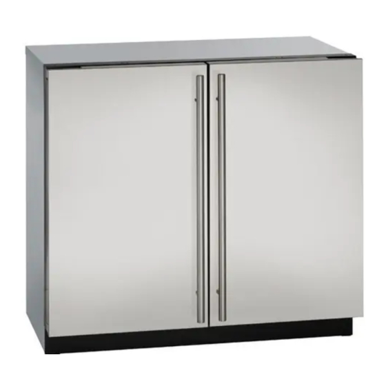
36" solid door
Hide thumbs
Also See for 3036RR:
- Quick reference manual (2 pages) ,
- User manual & service manual (11 pages) ,
- User manual (30 pages)

Related Manuals for U-Line 3036RR


Summary of Contents for U-Line 3036RR
- Page 1 USER GUIDE SAFETY • INSTALLATION & INTEGRATION • OPERATING INSTRUCTIONS • MAINTENANCE • SERVICE RIGHT PRODUCT. RIGHT PLACE. RIGHT TEMPERATURE. SINCE 1962. Modular 3000 Series 3036RR 36" Solid Door Refrigerator • •...
-
Page 2: Table Of Contents
USER GUIDE u-line.com SAFETY • INSTALLATION & INTEGRATION • OPERATING INSTRUCTIONS • MAINTENANCE • SERVICE Contents Intro Service Troubleshooting Safety Safety and Warning Warranty Disposal and Recycling Installation Environmental Requirements Electrical Cutout Dimensions Product Dimensions Side by Side Installation Anti-Tip Bracket... -
Page 3: U-Line.com
1. U-Line Customer Care must be contacted immediately at +1.800.779.2547. 2. Service or repairs performed on the unit without prior written approval from U-Line is not permitted. If the unit has been altered or repaired in the field without prior written approval from U-Line, claims will not be eligible. -
Page 4: Safety And Warning Warranty
USER GUIDE u-line.com SAFETY • INSTALLATION & INTEGRATION • OPERATING INSTRUCTIONS • MAINTENANCE • SERVICE Safety and Warning DANGER NOTICE This unit contains R600a (Isobutane) which is a Please read all instructions before installing, flammable hydrocarbon. It is safe for regular operating, or servicing the appliance. -
Page 5: Disposal And Recycling
USER GUIDE u-line.com SAFETY • INSTALLATION & INTEGRATION • OPERATING INSTRUCTIONS • MAINTENANCE • SERVICE Disposal and Recycling DANGER RISK OF CHILD ENTRAPMENT. Before you throw away your old refrigerator or freezer, take off the doors and leave shelves in place so children may not easily climb inside. -
Page 6: Environmental Requirements
USER GUIDE u-line.com SAFETY • INSTALLATION & INTEGRATION • OPERATING INSTRUCTIONS • MAINTENANCE • SERVICE Environmental Requirements This model is intended for indoor/interior applications only and is not to be used in installations that are open/ exposed to natural elements. - Page 7 USER GUIDE u-line.com SAFETY • INSTALLATION & INTEGRATION • OPERATING INSTRUCTIONS • MAINTENANCE • SERVICE Electrical WARNING SHOCK HAZARD — Electrical Grounding Required. Never attempt to repair or perform maintenance on the unit until the electricity has been disconnected. Never remove the round grounding prong from the plug and never use a two-prong grounding adapter.
-
Page 8: Cutout Dimensions
SAFETY • INSTALLATION & INTEGRATION • OPERATING INSTRUCTIONS • MAINTENANCE • SERVICE Cutout Dimensions CUTOUT DIMENSIONS PREPARE SITE Your U-Line product has been designed exclusively for a built-in installation. When built-in, your unit does not require additional air space for top, sides, or rear. Preferred location for electrical outlet However, the front grille must NOT be obstructed. -
Page 9: Product Dimensions
USER GUIDE u-line.com SAFETY • INSTALLATION & INTEGRATION • OPERATING INSTRUCTIONS • MAINTENANCE • SERVICE Product Dimensions Not Including Handle 23-7/16" (590 mm) 33-11/16" to 34-11/16" (856 to 881 mm) 35-7/16" (900 mm) 3-5/8" to 4-5/8" (92 to 118 mm) -
Page 10: Side By Side Installation
USER GUIDE u-line.com SAFETY • INSTALLATION & INTEGRATION • OPERATING INSTRUCTIONS • MAINTENANCE • SERVICE Side-by-Side Installation Hinge-by-Hinge Installation (Mullion) When installing two units hinge-by-hinge, 13/16" (22 mm) OTHER SITE REQUIREMENTS is required for integrated models. Additional space may be Side-by-Side Installation needed for any knobs, pulls or handles installed. -
Page 11: Anti-Tip Bracket
USER GUIDE u-line.com SAFETY • INSTALLATION & INTEGRATION • OPERATING INSTRUCTIONS • MAINTENANCE • SERVICE Anti-Tip Bracket 5. Using a 3/32" drill bit, drill 6 pilot holes (3 for each bracket) 5/8" (16 mm) deep into bottom of countertop. Use the anti-tip brackets as a template. - Page 12 USER GUIDE u-line.com SAFETY • INSTALLATION & INTEGRATION • OPERATING INSTRUCTIONS • MAINTENANCE • SERVICE 5. Using a 3/32" drill bit, drill 6 pilot holes (3 for each bracket) 5/8" (16 mm) deep into cabinetry frame using the anti-tip brackets as a template.
-
Page 13: General Installation
USER GUIDE u-line.com SAFETY • INSTALLATION & INTEGRATION • OPERATING INSTRUCTIONS • MAINTENANCE • SERVICE General Installation INSTALLATION 1. Plug in the power/electrical cord. 1. Use a level to confirm the unit is level. Level 2. Gently push the unit into position. Be careful not to should be placed along entangle the cord. -
Page 14: Integrated Grille / Plinth Dimensions
3. Apply double sided tape to the backside of the integrated grill (plinth strip/base fascia). Use the diagram below for reference. U-Line recommends ™ ™ tape, a high strength bonding tape. -
Page 15: Grille / Plinth Installation
USER GUIDE u-line.com SAFETY • INSTALLATION & INTEGRATION • OPERATING INSTRUCTIONS • MAINTENANCE • SERVICE Grille - Plinth Installation Installing the grille (plinth strip/base fascia) REMOVING AND INSTALLING GRILLE 1. Align slots in grille (plinth strip/base fascia) rail with (PLINTH STRIP/BASE FASCIA) -
Page 16: Door Swing
USER GUIDE u-line.com SAFETY • INSTALLATION & INTEGRATION • OPERATING INSTRUCTIONS • MAINTENANCE • SERVICE Door Swing Wall For Integrated models that are installed adjacent to a wall, 1/4" (6 mm) 1/4" (6 mm) clearance is recommended from wall on hinge side to allow the door to open 90°. -
Page 17: Door Stop
3. Once cover is removed, slide hinge pin into hole as shown. Pin should slide into place, stopping the door at Your U-Line unit was shipped to you with the optional 90° 90°; if the pin does not go into the hole shown, hold pin. -
Page 18: Door Adjust
USER GUIDE u-line.com SAFETY • INSTALLATION & INTEGRATION • OPERATING INSTRUCTIONS • MAINTENANCE • SERVICE Door Adjustments 4. The wrap hinges on top of the door. Carefully pull wrap away and then up. See below. DOOR ALIGNMENT AND ADJUSTMENT Align and adjust the door if it is not level or is not sealing properly. - Page 19 USER GUIDE u-line.com SAFETY • INSTALLATION & INTEGRATION • OPERATING INSTRUCTIONS • MAINTENANCE • SERVICE Alignment and Adjustment Procedure 1. Using a T-25 Torx Bit, loosen each pair of Torx head screws on both the upper and lower hinge plates.
-
Page 20: First Use
USER GUIDE u-line.com SAFETY • INSTALLATION & INTEGRATION • OPERATING INSTRUCTIONS • MAINTENANCE • SERVICE First Use All U-Line controls are preset at the factory. Initial startup requires no adjustments. NOTICE U-Line recommends allowing the unit to run overnight before loading with product. -
Page 21: Control Operation
USER GUIDE u-line.com SAFETY • INSTALLATION & INTEGRATION • OPERATING INSTRUCTIONS • MAINTENANCE • SERVICE Control Operation Your unit is equipped with two zones. Each zone can be set to a different mode. Zone Indicator Zone Toggle Zone Indicator Select... - Page 22 USER GUIDE u-line.com SAFETY • INSTALLATION & INTEGRATION • OPERATING INSTRUCTIONS • MAINTENANCE • SERVICE ® U-SELECT CONTROL Mode Settings Chart Digital Display Setting Default °F (°C) Range °F (°C) Red Wine 55 (12) 55 - 65 (12 - 18)
- Page 23 INTERIOR LIGHTING cooled to a point below optimum or frozen. Your U-Line 3000 Series unit uses a state of the art LED lighting system. The 3036 model dual zone’s lighting can The following chart lists modes which include the quick be independently controlled or set as a group.
- Page 24 ERROR NOTIFICATION CUSTOMER MENU The 3000 model series continuously monitors a series of The 3000 Series of U-Line undercounter refrigeration inputs and parameters to ensure proper and efficient appliances contains a feature rich customer menu. The operation of your unit. Should the system detect a fault,...
- Page 25 ENGLISH 3. To return to the Customer Menu, press and select “Return to Menu”. Down The U-Line 3000 Series of models supports a number of display languages including English, Spanish, French and Energy Saver Mode German. Energy Saver Mode Select Indicator 1.
- Page 26 USER GUIDE u-line.com SAFETY • INSTALLATION & INTEGRATION • OPERATING INSTRUCTIONS • MAINTENANCE • SERVICE Sound Level 2. Press . The selection will begin to flash. Select 3. Press to select between °F (Fahrenheit) or °C RETURN TO MENU (Celsius).
- Page 27 To access the Help Menu, select Help from the Customer Menu. Press to scroll through available information. The Help screen displays the following: • Model. • U-Line contact information. • Software version. • Serial Number. To exit the Help menu, press to select “Return to Menu”...
-
Page 28: Sabbath Mode
USER GUIDE u-line.com SAFETY • INSTALLATION & INTEGRATION • OPERATING INSTRUCTIONS • MAINTENANCE • SERVICE 7. Press to change “Off” to “On”. Sabbath Mode 8. Press to confirm your selection. The Display will fade out as the unit enters Sabbath Mode. -
Page 29: Airflow And Product Loading
Do not install the unit behind a door. When properly loaded, your U-Line unit will store up to 208 (12 oz. [330 ml]) cans or 136 (12 oz. [330 ml]) bottles. -
Page 30: Refrigerator Bins / Crisper
USER GUIDE u-line.com SAFETY • INSTALLATION & INTEGRATION • OPERATING INSTRUCTIONS • MAINTENANCE • SERVICE Cleaning Refrigerator Bins - Crisper Bins may be cleaned in a soapy warm water solution. A general household disinfectant, safe for plastics, may be REFRIGERATOR BIN INSTALLATION & REMOVAL used if necessary. -
Page 31: Maintenance
® monthly. For best results use Claire Stainless Steel Polish and Cleaner, which can be purchased from U-Line Rinse the interior using a soft sponge and clean water. Corporation (Part Number 173348). Comparable products are acceptable. Frequent cleaning will remove surface contamination that could lead to rust. - Page 32 USER GUIDE u-line.com SAFETY • INSTALLATION & INTEGRATION • OPERATING INSTRUCTIONS • • SERVICE MAINTENANCE NOTICE The drain pan was not designed to capture the water created when manually defrosting. To prevent water from overflowing the drain pan and possibly damaging water sensitive flooring, the unit must be removed from cabinetry.
-
Page 33: Cleaning Condenser
USER GUIDE u-line.com SAFETY • INSTALLATION & INTEGRATION • OPERATING INSTRUCTIONS • MAINTENANCE • SERVICE Cleaning Condenser INTERVAL - EVERY SIX MONTHS To maintain operational efficiency, keep the front grille (plinth strip/base fascia) free of dust and lint, and clean the condenser when necessary. -
Page 34: Extended Non-Use
If the unit will be exposed to temperatures of 40°F (5°C) or less, the steps above must be followed. For questions regarding winterization, please call U-Line at +1.800.779.2547. CAUTION Damage caused by freezing temperatures is not covered by the warranty. - Page 35 • Compressor: The compressor makes a hum or pulsing sound that may be heard when it operates. BEFORE CALLING FOR SERVICE If you think your U-Line product is malfunctioning, read • Evaporator: Refrigerant flowing through an evaporator the CONTROL OPERATION section to clearly understand may sound like boiling liquid.
- Page 36 12H+ temperature +10° and sealing. Contact properly. For other error codes contact over set point for Customer Care if U-Line Customer Service. over 12 hours. persistent. Product Is Because product in contact with the rear wall (L) (R) Temp Lo...
- Page 37 USER GUIDE u-line.com SAFETY • INSTALLATION & INTEGRATION • OPERATING INSTRUCTIONS • MAINTENANCE • SERVICE 6. After 24 hours, check the temperature of the water. If required, adjust the temperature control in a small increment (see CONTROL OPERATION). Causes which affect the internal temperatures of the cabinet include: •...
- Page 38 God, such as fire, floods, wind, and U-Line product to be free from defects in materials and lightning; damages incurred or resulting from shipping, workmanship for a period of five years from the date of improper installation, unauthorized modification, or purchase.
- Page 39 7. If a product defect is discovered during the applicable warranty period, you must promptly notify either U-Line at 8900 N. 55th Street, Milwaukee, Wisconsin 53223 USA or at +1.800.779.2547 or the dealer from whom you purchased the product. In no event shall such notification be received later than 30 days after the expiration of the applicable warranty period.