Table of Contents
Advertisement
Quick Links
Advertisement
Table of Contents

Related Manuals for Boss Audio Systems 642CA


Summary of Contents for Boss Audio Systems 642CA
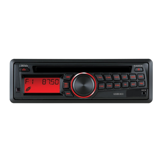
- Page 2 642CA OWNER’S MANUAL Mobile Audio System PLL Synthesizer Stereo Radio CD/MP3/WMA Player Automatic Memory Storing Full Detachable Panel Preset Equalization Electronic Shockproof (ESP) Function Auxiliary Input Function Remote Control...
-
Page 3: Table Of Contents
CONTENTS Installation ........... 3 Repeating tracks ....... 11 Take out screw before installation ..3 Playing tracks in random ....11 DIN Front-Mount (Method A)....3 Ejecting a disc ........11 Installing the unit ....... 3 Special function for MP3/WMA disc...11 Removing the unit ......4 Disc notes ..........12 DIN Rear-Mount (Method B) .... -
Page 4: Installation
INSTALLATION Notes: TAKE OUT SCREW BEFORE INSTALLATION Choose the mounting location where Before install the unit, please remove the the unit will not interfere with the normal two screws. driving function of the driver. Take out screw Before finally installing the unit, connect before installation. -
Page 5: Removing The Unit
INSTALLATION to fit your vehicle’s mounting area. Then use the supplied hardware (Tapping Screw and Plain Washer) to attach the other end of metal strap to a solid metal part of the vehicle under the dashboard. This strap also helps ensure proper electrical grounding of the unit. -
Page 6: Din Rear-Mount (Method B)
INSTALLATION Note: The outer trim ring, sleeve and the 5. Insert both of the supplied keys into the metal strap are not used for method B slots at the middle left and right sides of installation. the unit, then pull the unit out of the dashboard. -
Page 7: Using The Detachable Front Panel
Precautions when handing USING THE DETACHABLE FRONT PANEL Do not drop the front panel. REMOVING THE FRONT PANEL Precautions when handling 1. Press the release button on the front 1. Do not drop the front panel. panel and pull off the front panel. 2. -
Page 8: Wiring Connection
WIRING CONNECTION FOR 50X4W SYSTEM... -
Page 9: Operation
OPERATION LOCATION OF KEYS release button 13. Liquid crystal display (tune/seek/track up) 14. BND/LOU/ENT button 3. Volume knob (when rotated) (tune/seek/track down) SEL button (when pressed) 16. 4 SHF button 4. Disc slot 17. Auxiliary input jack 5. 1 PAU button 18. -
Page 10: Basic Operation
OPERATION BASIC OPERATION SET THE CLOCK SWITCHING ON/OFF THE UNIT Press the DISP button (22) until the clock is shown on the display. Then hold the Press PWR/MUT button (23) to switch on button until the clock flashes. Then press the unit. -
Page 11: Radio Operation
OPERATION The reset button is to be activated for the - Program scanning following reasons: Press AS/PS button (10) shortly to scan Initial installation of the unit when all preset station. When the field strength wiring is completed. level is more than the threshold level of All the function buttons do not operate. -
Page 12: Previewing Tracks
OPERATION “Searching track directly” => “Searching PREVIEWING TRACKS Directory or File Name”=> “Navigation” Press SCN button (6) to play first several seconds of each track on the current disc. from root => “Navigation” from current Press again to stop intro and listen to track. directory. -
Page 13: Disc Notes
OPERATION C. Notes on MP3 files (MP3 Version 3) DISPLAY INFORMATION Only): Press DISP button (22) to show the 1. The disc must be in the ISO9660 level 1 following information, such as the clock, or level 2 format, or Joliet or Romeo in ID3 TAG (if available: song title, directory the expansion format. -
Page 14: Remote Control
REMOTE CONTROL 1. VOL+: Volume Up Button (Character Select (A, B~8,9,0, _,-,+) For MP3/WMA Operation) MUTE: Power ON/OFF/MUTE Button 3. SELECT: Sound Mode Select Button (Character Shift Right For MP3/WMA Operation) 4. TUNE/SKIP : Tune/Seek Down Button 5. DISP: Display Button 6. -
Page 15: Specification
SPECIFICATION GENERAL Power Supply Requirements : DC 12 Volts, Negative Ground Chassis Dimensions : 178 (W) x 160 (D) x 50 (H) Tone Controls Bass (at 100 Hz) : ±10 dB Treble (at 10 kHz) : ±10 dB Maximum Output Power : 50X4 watts Current Drain : 5 Ampere (max.) -
Page 16: Trouble Shooting
TROUBLE SHOOTING Before going through the checklist, check wiring connection. If any of the problems persist after checklist has been made, consult your nearest service dealer. Symptom Cause Solution The car ignition switch is If the power supply is No power. not on.