Table of Contents
Advertisement
TopPage
PRECAUTIONS TO BE OBSERVED BEFORE AND
DURING SERVICING TO AVOID POSSIBLE EXPO-
SURE TO EXCESSIVE MICROWAVE ENERGY
BEFORE SERVICING
CHAPTER 1. WARNING TO SERVICE PERSONNEL
CHAPTER 2. MICROWAVE MEASUREMENT PRO-
CEDURE
CHAPTER 3. FOREWORD AND WARNING
CHAPTER 4. PRODUCT DESCRIPTION
CHAPTER 5. GENERAL INFORMATION
CHAPTER 6. OPERATION
SERVICE MANUAL
MODEL
In the interest of user-safety the oven should be restored to its origi-
nal condition and only parts identical to those specified should be
used.
WARNING TO SERVICE PERSONNEL: Microwave ovens con-
tain circuitry capable of producing very high voltage and cur-
rent, contact with following parts may result in a severe,
possibly fatal, electrical shock. (High Voltage Capacitor, High
Voltage Power Transformer, Magnetron, High Voltage Rectifier
Assembly, High Voltage Harness etc..)
CONTENTS
CHAPTER 7. TROUBLESHOOTING GUIDE
CHAPTER 8. TEST PROCEDURES
CHAPTER 9. TOUCH CONTROL PANEL ASSEMBLY
CHAPTER 10. PRECAUTIONS FOR USING LEAD-
FREE SOLDER
CHAPTER 11. COMPONENT REPLACEMENT AND
ADJUSTMENT PROCEDURE
CHAPTER 12. CIRCUIT DIAGRAMS
Parts List
SY612R408LPSTF
MICROWAVE OVEN
R-408LS
This document has been published to be used for
after sales service only.
The contents are subject to change without notice.
R408LS
Advertisement
Table of Contents

Related Manuals for Sharp R-408LS


Summary of Contents for Sharp R-408LS
- Page 1 TopPage R408LS SERVICE MANUAL SY612R408LPSTF MICROWAVE OVEN R-408LS MODEL In the interest of user-safety the oven should be restored to its origi- nal condition and only parts identical to those specified should be used. WARNING TO SERVICE PERSONNEL: Microwave ovens con-...
-
Page 2: Table Of Contents
CONTENTS PRECAUTIONS TO BE OBSERVED BEFORE [13] L: RELAY TEST .......... 8-5 AND DURING SERVICING TO AVOID POSSIBLE [14] M: DEFROST TEST........8-6 EXPOSURE TO EXCESSIVE MICROWAVE ENER- [15] N: FOIL PATTERN ON THE PRINTED WIRING BOARD TEST....... 8-6 BEFORE SERVICING CHAPTER 9. -
Page 3: Precautions To Be Observed Before
Before servicing an operative unit, perform a microwave emission check as per the Microwave Measurement Procedure outlined in this service manual. If microwave emissions level is in excess of the specified limit, contact SHARP ELECTRONICS CORPORATION immediately @1-800-237-4277. If the unit operates with the door open, service person should 1) tell the user not to operate the oven and 2) contact SHARP ELECTRONICS CORPORATION and Food and Drug Administration's Center for Devices and Radiological Health immediately. -
Page 4: When The Testing Is Completed
R408LS CHAPTER 1. R408LS WARNING TO SERVICE PERSONNEL Service Manual Microwave ovens contain circuitry capable of producing very high voltage and current, contact with following parts may result in a severe, possibly fatal, electrical shock. (Example) High Voltage Capacitor, High Voltage Power Transformer, Magnetron, High Voltage Rectifier Assembly, High Voltage Harness etc.. Read the Service Manual carefully and follow all instructions. -
Page 5: Chapter 2. Microwave Measurement Procedure
R408LS CHAPTER 2. R408LS MICROWAVE MEASUREMENT PROCEDURE Service Manual [1] Requirements: 1. Microwave leakage limit (Power density limit): The power density of microwave radiation emitted by a microwave oven should not exceed 1mW/ at any point 5cm or more from the external surface of the oven, measured prior to acquisition by a purchaser, and thereafter (through the use- ful life of the oven), 5 mW/cm at any point 5cm or more from the external surface of the oven. -
Page 6: Chapter 3. Foreword And Warning
Service Manual [1] FOREWORD This Manual has been prepared to provide Sharp Electronics Corp. Service Personnel with Operation and Service Information for the SHARP MICROWAVE OVEN, R-408LS. It is recommended that service personnel carefully study the entire text of this manual so that they will be qualified to render satisfactory customer service. -
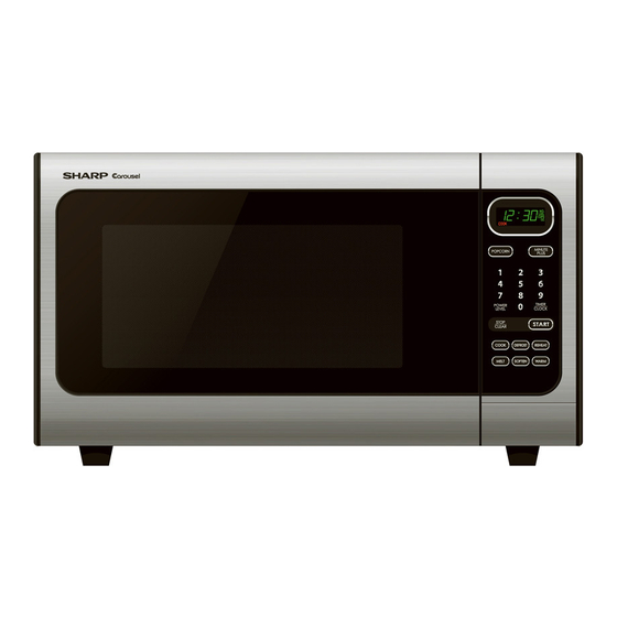
Page 7: Chapter 4. Product Description
R408LS CHAPTER 4. R408LS PRODUCT DESCRIPTION Service Manual [1] SPECIFICATIONS ITEM DESCRIPTION 120 Volts Power Requirements 60 Hertz Single phase, 3 wire grounded Power Consumption 1600W / Approx. 13.5 Amperes 1100 W nominal of RF microwave energy (IEC Test procedure) Power Output Operating frequency 2450 MHz Width 21-5/8"... -
Page 8: Chapter 5. General Information
R408LS CHAPTER 5. R408LS GENERAL INFORMATION Service Manual [1] GROUNDING INSTRUCTIONS This oven is equipped with a three prong grounding plug. It must be plugged into a wall receptacle that is properly installed and grounded in accor- dance with the National Electrical Code and local codes and ordinances. In the event of an electrical short circuit, grounding reduces the risk of electric shock by providing an escape wire for the electric current. - Page 9 R408LS 2. TOUCH CONTROL PANEL NOTE: Some one-touch cooking features such as “MINUTE PLUS” are disabled after three minutes when the oven is not in use. These fea- tures are automatically enabled when the door is opened and closed or the STOP/ CLEAR pad is pressed. 5 –...
-
Page 10: Chapter 6. Operation Description Of Operating Se- Quence
R408LS CHAPTER 6. R408LS OPERATION Service Manual [1] DESCRIPTION OF OPERATING SEQUENCE The following is a description of component functions during oven operation. 1. OFF CONDITION 3. POWER LEVEL P-0 TO P-90 COOKING Closing the door activates the door sensing switch and primary inter- When Variable Cooking Power is programmed, the 120 volts A.C. -
Page 11: Oven Schematic
R408LS [2] OVEN SCHEMATIC 1. Off Condition SCHEMATIC NOTE: CONDITION OF OVEN 1. DOOR CLOSED 2. CLOCK APPEARS ON DISPLAY NOTE: " " indicates components with potentials above 250V DOOR SENSING SWITCH POWER TRANSFORMER (RY2) SECONDARY INTERLOCK RELAY 120VAC 60Hz CONTROL UNIT (RY1) HIGH... -
Page 12: Description And Function Of Components
R408LS [3] DESCRIPTION AND FUNCTION OF COMPONENTS 1. DOOR OPEN MECHANISM 4. TURNTABLE MOTOR The door is opened by pushing the open button on the control panel, The turntable motor rotates the turntable located on the bottom of the refer to the Figure D-1. When the open button is pushed, the open but- oven cavity, so that the foods on the turntable cook evenly during ton pushes up the switch lever, and then the switch lever pushes up cooking. -
Page 13: Chapter 7. Troubleshooting Guide
R408LS CHAPTER 7. R408LS TROUBLESHOOTING GUIDE Service Manual Never touch any part in the circuit with your hand or an uninsulated tool while the power supply is connected. When troubleshooting the microwave oven, it is helpful to follow the Sequence of Operation in performing the checks. Many of the possible causes of trouble will require that a specific test be performed. -
Page 14: Chapter 8. Test Procedures
R408LS CHAPTER 8. R408LS TEST PROCEDURES Service Manual [1] A: MAGNETRON ASSEMBLY TEST 1. Disconnect the power supply cord, and then remove outer case. 2. Open the door and block it open. 3. Discharge high voltage capacitor. 4. To test for an open filament, isolate the magnetron from the high voltage circuit. A continuity check across the magnetron filament leads should indicate less than 1 ohm. -
Page 15: D: High Voltage Capacitor Test
R408LS 5. Reconnect all leads removed from components during testing. 6. Reinstall the outer case (cabinet). 7. Reconnect the power supply cord after the outer case is installed. 8. Run the oven and check all functions. NOTE: Be sure to use an ohmmeter that will supply a forward bias voltage of more than 6.3 volts. [4] D: HIGH VOLTAGE CAPACITOR TEST 1. -
Page 16: F: Secondary Interlock System Test
R408LS [7] F: SECONDARY INTERLOCK SYSTEM TEST 1. DOOR SENSING SWITCH 1. Disconnect the power supply cord, and then remove outer case. 2. Open the door and block it open. 3. Discharge high voltage capacitor. 4. Isolate the switch and connect the ohmmeter to the common (COM.) and normally open (NO) terminal of the switch. The meter should indicate an open circuit with the door open and a closed circuit with the door closed. -
Page 17: H: Blown Monitor Fuse Test
R408LS [9] H: BLOWN MONITOR FUSE TEST 1. Disconnect the power supply cord, and then remove outer case. 2. Open the door and block it open. 3. Discharge high voltage capacitor. 4. If the monitor fuse is blown when the door is opened, check the primary interlock switch, secondary interlock relay (RY2), relay (RY1) and monitor switch according to the “TEST PROCEDURE”... -
Page 18: K: Key Unit Test
R408LS 1) In connection with pads. a) When touching the pads, a certain group of pads do not produce a signal. b) When touching the pads, no pads produce a signal. 2) In connection with indicators a) At a certain digit, all or some segments do not light up. b) At a certain digit, brightness is low. -
Page 19: M: Defrost Test
R408LS 3. Discharge high voltage capacitor. 4. Disconnect the leads to the primary of the power transformer. 5. Ensure that these leads remain isolated from other components and oven chassis by using insulation tape. 6. After that procedure, re-connect the power supply cord. 7. - Page 20 R408LS 5) Make a visual inspection of the varistor. Check for burned damage and examine the transformer with a tester for the presence of layer short-circuit (check the primary coil resistance which is approximately 563Ω±10%). If any abnormal condition is detected, replace the control unit. 6) Reconnect all leads removed from components during testing.
-
Page 21: Chapter 9. Touch Control Panel Assem- Bly
R408LS CHAPTER 9. R408LS TOUCH CONTROL PANEL ASSEMBLY Service Manual [1] OUTLINE OF TOUCH CONTROL PANEL 3) Power Source Circuit This circuit generates voltage necessary in the control unit from the The touch control section consists of the following units. AC line voltage. - Page 22 R408LS 2. Servicing the touch control panel with power supply from an exter- nal power source: Disconnect the touch control panel completely from the oven proper, and short both ends of the door sensing switch (on PWB) of the touch control panel, which brings about an operational state that is equivalent to the oven door being closed.
-
Page 23: Chapter 10. Precautions For Using Lead- Free Solder
R408LS CHAPTER 10. R408LS PRECAUTIONS FOR USING LEAD-FREE SOLDER Service Manual [1] Employing lead-free solder The “Main PWB” of this model employs lead-free solder. This is indicated by the “LF” symbol printed on the PWB and in the service manual. The suffix letter indicates the alloy type of the solder. -
Page 24: Chapter 11. Component Replacement
1. Door does not close firmly. 4. If the outer case (cabinet) is not fitted. WARNING FOR WIRING To prevent an electric shock, take the following precau- 3) Sharp edge: tions. Bottom plate, Oven cavity, Waveguide flange, 1. Before wiring, Chassis support and other metallic plate. -
Page 25: Outer Case Removal
R408LS [2] OUTER CASE REMOVAL To remove the outer case, procedure as follows. 1. Disconnect the power supply cord. 2. Open the oven door and block it open. 3. Remove the two (2) screws from the lower portion of the rear cabi- net using a T20H Torx type or GTXH20-100 screw driver. -
Page 26: Oven Lamp Removal
4. Where the corners have been snipped off bend corner areas flat. 8. After replacement use the one (1) screw XOTS740P10000 to fit the No sharp edges must be evident after removal of the turntable turntable motor cover. motor cover. -
Page 27: Control Panel Assembly Removal
R408LS 5. Install the fan motor assembly to the oven cavity back plate with 6. Connect the wire leads to the magnetron and fan motor, referring to two (2) screws. the pictorial diagram. Coil Shaft Groove joint pliers Shaft These are the positions Axis that should be pinched Stator... -
Page 28: Door Sensing Switch/Primary Interlock Switch And Monitor Switch Removal
R408LS [12] DOOR SENSING SWITCH/PRIMARY INTERLOCK SWITCH AND MONITOR SWITCH REMOVAL 1. REMOVAL At this time switch lever will be free, do not lose it. 1. Disconnect the power supply cord and remove outer case. 2. REINSTALLATION 2. Open the door and block it open. 1. - Page 29 R408LS 4. Check for microwave leakage around door with an approved micro- wave survey meter. (Refer to Microwave Measurement Procedure.) Door stopper NOTE: The door on a microwave oven is designed to act as an electronic seal preventing the leakage of microwave energy from oven cavity during cook cycle.
-
Page 30: Chapter 12. Circuit Diagrams
R408LS CHAPTER 12. R408LS CIRCUIT DIAGRAMS Service Manual [1] Pictorial Diagram (Figure S-1) Figure S-1. Pictorial Diagram 12 – 1... -
Page 31: Control Panel Circuit (Figure S-2)
R408LS [2] Control Panel Circuit (Figure S-2) Figure S-2. Control Panel Circuit 12 – 2... -
Page 32: Printed Wiring Board (Figure S-3)
R408LS [3] Printed Wiring Board (Figure S-3) Figure S-3. Printed Wiring Board 12 – 3... -
Page 33: Parts List
HOW TO ORDER REPLACEMENT PARTS MICROWAVE OVEN To have your order filled promptly and correctly, please furnish the following information. 1. MODEL NUMBER R-408LS MODEL 2. REF. NO. 3. PART NO. 4. DESCRIPTION Parts marked "*" may cause undue microwave exposure. - Page 34 R408LS [1] OVEN PARTS 7-10 7-10 4-13 4-11 1-10 4-15 7-11 7-10 4-12 7-10 1-11 4-10 1-12 4-14 1-13 7-10 7-10...
- Page 35 R408LS PRICE PART PARTS CODE DESCRIPTION RANK MARK RANK [1] OVEN PARTS ELECTRIC PARTS Noise filter assembly FPWBFA417WRKZ Noise filter assembly (Interchangeable) FPWBFA389WRKZ Monitor fuse 20A and monitor switch(V-5220Q) FFS-BA033WRKZ Monitor fuse 20A and monitor switch(D3V-1G-2C25) (Interchangeable) FFS-BA037WRKZ Temp. fuse 150C (Magnetron) QFS-TA013WRE0 Primary interlock switch/ door sensing switch QSW-MA085WRE0...
- Page 36 R408LS [2] DOOR AND CONTROL PANEL PARTS 5-3-1 5-3-2 3-1-2 3-1-4 3-1-1-1 3-1-1 3-1-3 3-1-1-2 Actual wire harness may be different from illustration. 3-1-5...
- Page 37 R408LS PRICE PART PARTS CODE DESCRIPTION RANK MARK RANK [2] DOOR AND CONTROL PANEL PARTS CONTROL PANEL PARTS Panel med assembly DPNLCC019WRKZ 3-1-1 Open button assembly FBTN-A164WRKZ 3-1-1-1 Open button JBTN-B391WRFZ 3-1-1-2 Button decoration HDECQA328WRPZ 3-1-2 Panel decoration HDECQA329WRPZ 3-1-3 Open button spring MSPRCA157WREZ 3-1-4...
- Page 38 R408LS INDEX PRICE PART PRICE PART PARTS CODE PARTS CODE RANK MARK RANK RANK MARK RANK RTRN-A746WRZZ 1-1-13 [ D ] RV-MZA346WRZZ 1-1-5 DPNLCC019WRKZ 2-3-1 DPWBFC563WRKZ 2-3-2 [ T ] TCAUAA292WRRZ 1-6-3 [ F ] FACCDA083WRE0 1-1-7 TCAUAA296WRRZ 1-6-4 TINSEB137WRRZ 2-6-7 FACCDA085WREZ 1-1-7...
- Page 40 EndPage COPYRIGHT © 2006 BY SHARP CORPORATION ALL RIGHTS RESERVED. No part of this publication may be reproduced, stored in retrieval systems, or transmitted in anyform or by any means, electronic, mechanical, photocopying, re- cording, or other wise, without prior written permission...