Table of Contents
Advertisement
Quick Links
Advertisement
Table of Contents

Related Manuals for Crestron PAC2


Summary of Contents for Crestron PAC2
- Page 1 Crestron PAC2 Professional Automation Computer Operations Guide...
- Page 2 This document was prepared and written by the Technical Documentation department at: Crestron Electronics, Inc. 15 Volvo Drive Rockleigh, NJ 07647 1-888-CRESTRON All brand names, product names and trademarks are the property of their respective owners. ©2002 Crestron Electronics, Inc.
-
Page 3: Table Of Contents
Troubleshooting Communications ... 22 Compiling and Uploading a D3 Pro Program to the Control System... 23 Compiling and Uploading a SIMPL Windows Program to the PAC2 ... 25 Uploading Web pages to the PAC2... 27 Uploading Touchpanel Projects via the PAC2 ... 27 Updating the Operating System... -
Page 5: Professional Automation Computer: Pac2
Crestron's unique dual bus system, with its high-speed I/O bus architecture, provides blazing fast throughput, system wide. The two 40Mb/s Y-BUS expansion slots offer the option of installing any of the CNX-series cards listed in Crestron’s 2003 Product Catalog, and all C2-series control cards. The 300Mb/s Z-BUS expansion slot is designed for super high-speed control card applications such as 10/100 Ethernet, Operations Guide –... - Page 6 There are eight normally open relays, isolated with MOV suppression. The 32 Cresnet located on the top of the PAC2 (NET A – NET H). When powered by the internal supply or an external power supply, they expand the number of Cresnet devices that can be connected to the PAC2.
-
Page 7: Specifications
Weight: For more information on system memory usage, refer to “On-Board Memory” on page 10. 40 Mb/s parallel communications; supports any of the CNX-series cards listed in Crestron’s 2003 Product Catalog and all C2-series control cards. Professional Automation Computer: PAC2 • 3 DETAILS ®... - Page 8 Optional Z-BUS Cards: Single port 10/100 Ethernet, Dual Port WAN-LAN-10/100 Ethernet, or Dual Port WAN-LAN-10/100 Ethernet-USB. The PAC2 provides a maximum of 50 watts (DC) for all network devices. Depending on the network power requirements, it may be necessary to add one or more Crestron external 24VDC supplies.
-
Page 9: Physical Description
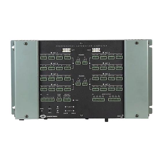
Crestron PAC2 Physical Description The PAC2 automation control system is housed in a gray and black enclosure with labeling on the top and front panels. The dimensions are shown in the illustrations on the next page. PAC2 Physical View without Optional Y and Z Bus Cards PAC2 Top View with Optional Jumpered 3-Pin Mini Connector Installed in POWER 1 Port Operations Guide –... - Page 10 Professional Automation Computer PAC2 Physical Views Top View Refer to "Built-in Cresnet Hub/Repeater" in this guide for wiring details and power requirements for the PAC2 NET connectors. Front View Left Side View 6 • Professional Automation Computer: PAC2 14.00 in (35.56 cm)
- Page 11 Operations Guide – Doc. 5941 Professional Automation Computer Ports/Connectors The ports/connectors provided on the top and front panel of the PAC2 are described in the following paragraphs. LEFT, RIGHT These 5-position connectors, rated at 24VDC, 2A maximum load, provide for Cresnet signals and an additional override contact closure signal.
- Page 12 Provides a dry contact closure fault signal to notify an external control system when the PAC2 has a system fault. This output should be connected to a digital input of the backup computer. The fault signal is active low. A fault is defined as the CPU not interacting with Cresnet for 10 seconds.
-
Page 13: Built-In Cresnet Hub/Repeater
‘disconnected’ from the other segments in operation. The LEDs for these segments are not illuminated. CAUTION: Use only Crestron power supplies for Crestron equipment. Failure to do so could cause equipment damage or void the Crestron warranty. Power for the hub is supplied through POWER ports 1, 2, 3, and 4, to segment pairs, as shown in the illustration on the next page. -
Page 14: On-Board Memory
In the illustration above, one of the supplied 3-pin mini connectors with installed jumper wire is plugged into the POWER 1 port. The PAC2’s internal power supply is connected to the INT pin; the port’s EXT pin is connected to the 24 pin of each connector in the segment pair. - Page 15 RAM, Analog RAM from database, Serial RAM, Serial RAM from database, Analog Non-volatile Ramp, Digital RAM, etc.) *Commonly used for presets (volume/lighting/dial #s). 1. Digital, analog and serial signal values 2. SIMPL+ Variables (if "volatile" qualifier is used, or #DEFAULT_VOLATILE is used) Professional Automation Computer: PAC2 • 11 DESCRIPTION...
-
Page 16: Expandable Memory (Compact Flash)
(1) this device may not cause harmful interference, and (2) this device must accept any interference received, including interference that may cause undesired operation. 12 • Professional Automation Computer: PAC2 hard drive. The slot is accessible on the 1. -
Page 17: Setup
(e.g., use of power strips). The PAC2 has two flanges that allow the unit to be mounted in a CAEN. Refer to the latest revision of the CAEN – Automation Enclosures Installation Guide (Doc. 5940) for more information on the CAEN. -
Page 18: Ac Power Connection
PAC2 AC Power Connection The PAC2 requires AC power for operation. This can be accomplished using the materials listed in the following table. This involves adding the terminal blocks and associated parts to the lower left terminal rail in a double-wide CAEN enclosure, or the lower terminal rail in a single-wide enclosure, and making the necessary wiring connections. - Page 19 Crestron PAC2 PAC2 AC Power Source Assembly and Connection Diagram To PAC2 Operations Guide – Doc. 5941 Professional Automation Computer From To GND From Strip NEUTRAL Rail 1. Assemble the supplied terminal blocks, partition plate, end plate, and end bracket to the power rail, as shown. Ensure that the parts are snug against the existing hardware, and tighten the end bracket screw to secure the parts in place.
-
Page 20: Bussing Strip Installation
Professional Automation Computer Bussing Strip Installation The PAC2 is supplied with two brass bussing strips to facilitate commoning (linking) of the S5 Relay Output terminal block connections. The bussing strips are constructed with four terminal block positions, and may be trimmed to size for various applications or different devices. -
Page 21: Hardware Hookup
Where: R = Resistance (refer to table below). L = Length of run (or chain) in feet. PF = Power factor of entire run (or chain). RESISTANCE (R) WIRE GAUGE Doubled CAT5 Tripled CAT5 Professional Automation Computer: PAC2 • 17... - Page 22 Hookup Connections for the 2-Series Automation Control System (front panel) Hookup Connections for the 2-Series Automation Control System (top panel) 18 • Professional Automation Computer: PAC2 S3 Z-BUS To CLX-series 24 VDC to hub...
-
Page 23: Establishing Communication With The Pac2
Port = COM 1 through COM 8. Select the correct COM port on the PC. • Baud rate = 115200 (You can set the PC and the PAC2 to a different baud rate, by using the Functions | Set Baud Rate command. - Page 24 For TCP/IP, use CAT5 straight through cables with 8-pin RJ-45 connectors to connect the LAN port on the PAC2 and the LAN port on the PC to the Ethernet hub. Alternatively, you can use a CAT5 crossover cable to connect the two LAN ports directly, without using a hub.
-
Page 25: Setting Network Ids In D3 Pro
For information on setting network IDs, refer to the detailed information contained in the D3 Pro help file, or in Crestron’s D3 Pro Reference Guide, Doc. 5998. The latest version is available as a PDF on the Crestron website (www.crestron.com). -
Page 26: Troubleshooting Communications
(e.g., for a modem). Consult the manufacturer’s documentation for further information about the COM ports on your 3. Check the ERR LED indicator on the top panel of the PAC2. If this LED is illuminated, unplug the unit and reapply power after a few seconds. -
Page 27: Compiling And Uploading A D3 Pro Program To The Control System
Programming View. However, D3 Pro will not automatically open the VisionTools After all the touchpanel projects are created, D3 Pro will generate the PAC2 logic program. A progress bar will display information about the program as it is created and compiled. - Page 28 TCP/IP, then you would select TCP/IP as the connection type and enter the IP address of the PAC2. With touchpanels, various connection types are possible. If the panel is connected to the PAC2, specify the type of connection between the PC and the PAC2: Serial or TCP/IP. Crestron PAC2...
-
Page 29: Compiling And Uploading A Simpl Windows Program To The Pac2
The compiled program will be stored as an SPZ file in the same directory as the source file. There are a number of ways to upload an SPZ file to the PAC2. When any of the options is selected, a “Send Program” window appears (refer to graphic on next page). - Page 30 NOTE: Unlike X-Series processors, the 2-Series processor does not require a permanent memory image. Also, the 2-Series adds the ability to automatically retrieve the current program from the PAC2. To do this, verify that the Retrieve Program from Control System before overwriting check box is selected.
-
Page 31: Uploading Web Pages To The Pac2
When the card is inserted into the Memory Expansion slot of the PAC2, the Web pages will be recognized as valid for e-Control so long as they are located in a directory called HTML. (The HTML directory must also include a configuration file called _config_ini_, which identifies the default page—contact... -
Page 32: Updating The Operating System
Professional Automation Computer Updating the Operating System As with all 2-Series control systems, operating system files for the PAC2 have a .cuz extension. You can obtain .cuz updates (when available) from the software downloads area of the Crestron website. To download an update, click the .cuz file and choose the Save to Disk option, then specify the directory where the update will be stored. -
Page 33: Advanced Console Commands
The SIMPL Windows online help file provides a full listing of console commands that are valid for 2-Series control systems. You can access the PAC2 console in a variety of ways: via a serial connection (RS-232) with a PC, over Ethernet via the LAN port, or through Telnet, among many other methods. - Page 34 Flash The following commands have been modified to enable processing functions for compact flash files/programs: Console Commands for Setting IP 30 • Professional Automation Computer: PAC2 • CD - Permits changing to a directory on compact flash • DELETE - Enables deleting files from compact flash.
-
Page 35: Programming Software
Crestron PAC2 Programming Software You can create a program to control the PAC2 control system using the Crestron programming tools D3 Pro or SIMPL Windows. Customers whose focus is on lighting systems may prefer to use the D3 Pro software since it is designed especially for creating lighting and environmental system control applications. - Page 36 10/100 Ethernet. Slot 4: C2I-IO8 The PAC2 provides eight I/O ports called Versiports, each of which can function as a digital input, a digital output, or an analog input. Each Versiport has a corresponding pullup resistor.
- Page 37 When Versiport 3 is shorted to ground, <i3> will go high. When Versiport 3 is not shorted to ground, <i3> will go low (so long as <pu-disable> equals 0 or is undefined). Professional Automation Computer: PAC2 • 33 VersiPort 1 Used for analog input.
- Page 38 Slot 6: C2Net-Device The C2Net-Device slot enables the PAC2 to control up to 252 Cresnet devices. Each Cresnet device is assigned a unique identifier called a Net ID, which is a hexadecimal value ranging from 03 to FE.
- Page 39 PAC2. To do this you first open SIMPL Windows, then drag the PAC2 from the Control Systems folder on the existing control system in System Views, drop it on top of the existing control system, and click Yes when prompted to confirm the replacement.
- Page 40 “Module Header Information” Window After you convert each module in a program, you can convert the program as described previously: drag the PAC2 onto the existing control system in System Views and click Yes to confirm the replacement. For further information about compile-time errors and detailed explanations about working with modules, refer to the SIMPL Windows online help file.
-
Page 41: Problem Solving
Used wrong serial port. Serial cable miswired. 1. Connect a DB9 straight-through RS-232 cable between the PAC2 and a PC. Refer to “Establishing Communication with the PAC2” on page 19 for more information. Professional Automation Computer: PAC2 • 37... -
Page 42: Battery Replacement
N (Parity), 8 (Data Bits) and 1 (Stop Bits) and click OK. 4. Power down the PAC2. 5. While powering up the PAC2, press and hold ALT and K on the keyboard until the following text (or similar) appears in Viewport: System Monitor [v1.001 (0001)]... -
Page 43: Serial Communication Difficulties With Other Devices Connected To The Control System
The COM analyzer also functions while the unit is in passthrough mode. Passthrough mode is accessed from the Crestron Viewport by selecting Functions | Enter Passthrough Mode (CNX / 2-Series only). The window, shown after this paragraph, is used to select the port configuration for passthrough mode. -
Page 44: Further Inquiries
For assistance in your local time zone, refer to the Crestron website (www.crestron.com) for a listing of Crestron worldwide offices. You can also log onto the online help section of the Crestron website to ask questions about Crestron products. First-time users will need to establish a user account to fully benefit from all available features. -
Page 45: Software License Agreement
This Agreement may only be modified by a writing signed by an authorized officer of Crestron. Updates may be licensed to You by Crestron with additional or different terms. This is the entire agreement between Crestron and You relating to the Software and it supersedes any prior representations, discussions, undertakings, communications or advertising relating to the Software. - Page 46 “applets” incorporated into the Software), the accompanying media and printed materials, and any copies of the Software are owned by Crestron or its suppliers. The Software is protected by copyright laws and international treaty provisions. Therefore, you must treat the Software like any other copyrighted material, subject to the provisions of this Agreement.
-
Page 47: Return And Warranty Policies
CRESTRON shall not be liable to honor the terms of this warranty if the product has been used in any application other than that for which it was intended, or if it has been subjected to misuse, accidental damage, modification, or improper installation procedures. - Page 48 Crestron Electronics, Inc. Operations Guide – DOC. 5941 15 Volvo Drive Rockleigh, NJ 07647 12.02 Tel: 888.CRESTRON Fax: 201.767.7576 Specifications subject to www.crestron.com change without notice.