Advertisement
Quick Links
Quick Start Guide
Visibly yours
Keyboard Port
Requires optional Tally Board.
Requires optional Tally Board.
Connect to customer supplied
Connect to 8 external devices for
PS-2 keyboard for entering
relay closure control. Refer to
names and values.
Appendix A for connector pinouts.
KEYBOARD
System Setup
System setup is comprised of 20 sequences,
each of which includes many steps. For
error-free installation, always refer to the
associated section in Chapter 5 of the User's Guide.
The circled sequence numbers are identical.
Before you begin, ensure that your system is properly
cabled. Use the sample charts on the back of this
guide, or refer to Chapter 3 in the User's Guide.
ID Setup and Remote Enable — Set up your
1
individual ScreenPRO-II IDs, and enable remote
control on each ScreenPRO-II.
System Power Up — Power up the entire system,
2
and download code (if required).
Return to Factory Default — Perform a complete
3
factory reset on all devices. This procedure resets all
router tables and source mappings.
Touch Screen Calibration — Calibrate the
4
Controller's Touch Screen display.
Store and recall system configurations
using customer supplied Flash Memory
Tally Connector
TALLY
Programming EDID — For your background and DSK
5
sources, program EDID to ensure proper
communications to your PCs at the preferred resolution.
Restore from Flash Memory Card — If you backed
6
up to Flash Memory, restore the configuration at this
point. No further setup steps are necessary.
Standard Destination Setup — Set up your single
7
screen destinations (maximum 4) and/or your
widescreen destination (maximum 1).
Router Setup — Set up your system's routing
8
switcher(s), including type, communications, output
patching, and designating Aux outputs.
Aux Destination Setup — Set up your system's
9
Auxiliary destinations, including Aux, ImagePRO Aux
and ScreenPRO-II Aux destinations as required.
Input Patching — Associate (patch) specific router
10
inputs to specific source buttons on the Controller.
Assign tally connections as desired.
Output Format Setup — Configure the output format
11
for each ScreenPRO-II in your system to the native
resolution of the display or projector.
Sync Setup — Set up sync parameters for the monitors
12
and projectors connected to the system.
Barco Media and Entertainment
11101 Trade Center Drive
Rancho Cordova, CA
95670 • USA
Memory Card Slot
For serial communications
with external devices such
Card (minimum size: 512 MB)
MEMORY CARD
EXT COMM
Console Port
CONSOLE
For serial communications
and downloading code.
Phone:
Technical Support:
Websites:
Ext Comm Port
Connect to Ethernet Switch on an isolated
network. Used for communications with
as routers.
devices such as video routers, matrix
switchers, BlendPRO-II and ScreenPRO-II.
Also used for downloading code.
T250V 2A FUSE
CAUTION: FOR CONTINUED PROTECTION
AGAINST RISK OF FIRE, REPLACE ONLY
ETHERNET
WITH SAME TYPE AND RATING OF FUSE
Genlock Setup — Set up Genlock for each destination
13
on the Output Menu. For a widescreen destination,
verify all BlendPRO-II "widescreen lock" connections.
Projector Setup — Set up your projectors for both
14
single screen and widescreen destinations.
Background Setup — Set up the two background
15
sources. Remember (on ScreenPRO-II) that BG/DSK
input B is shared between DSK and Background B.
Input Setup — Set up your system's inputs. For
16
widescreen configurations only, adjust each input's
phase and color balance at the output of BlendPRO-II.
DSK Setup — Set up the DSK as a DVI source or a
17
frame grab. Remember (on ScreenPRO-II) that BG/DSK
input B is shared between DSK and Background B.
LOGO Setup — Set up the LOGO as "black" or a frame
18
grab.
Save the Setup — From the Home Menu, press SAVE
19
to save the state of the Controller in non-volatile
memory.
Backup to Flash Memory Card — Back up your
20
system configuration to a customer-supplied Flash
Memory Card.
+1 (916) 859-2500
Fax:
+1 (916) 859-2515
+1 (866) 374-7878
www.folsom.com
www.events.barco.com
Ethernet Port
AC
Connect to AC
power source.
P/N 26-0505004-00, Rev A
Advertisement

Related Manuals for Barco ScreenPRO II


Summary of Contents for Barco ScreenPRO II
- Page 1 Barco Media and Entertainment Phone: +1 (916) 859-2500 11101 Trade Center Drive Fax: +1 (916) 859-2515 Rancho Cordova, CA Technical Support: +1 (866) 374-7878 95670 • USA Websites: www.folsom.com Quick Start Guide www.events.barco.com Visibly yours Memory Card Slot Ext Comm Port...
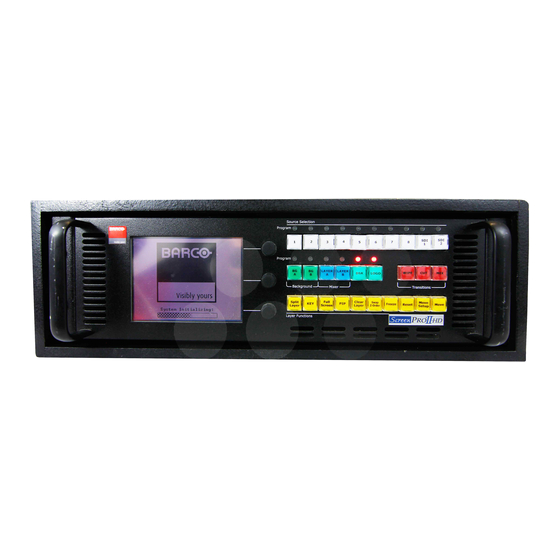
- Page 2 Layer Functions Section Source Selection Bus Red LEDs Each button is an input that can be assigned to a PIP, Change Take active Copy layer to Set up a Co-locate Toggle Solid: Source is on Program, associated destination is enabled Key or Aux destination active layer layer to full...
- Page 3 Joystick Section Touch Screen Menu Section Includes a 3-axis Joystick and Used for system configuration, dedicated buttons that enable you setup and operational adjustments, to adjust PIPs, Keys and many such as PIPs and Keys. additional system parameters. Destination / Aux Bus Presets Section Routes signals to one or more Stores and recalls Controller...
- Page 4 Sample System — External Routing Sample System — Internal Routing Widescreen Destination Single Screen Destinations Camera Aux Destination 1 Aux Destination 1 PresentationPRO-II PresentationPRO-II DVD or VTR Analog DA MatrixPRO RGBHV Router Aux Destination 2 Aux Destination 2 ImagePRO ImagePRO BlendPRO-II ScreenPRO-II #1 ScreenPRO-II #1...