Table of Contents
Advertisement
Available languages
Available languages
Quick Links
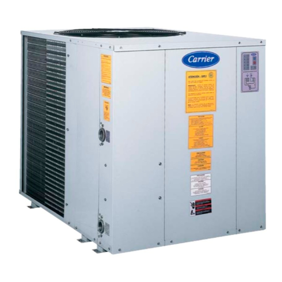
30AJ
UNIDADES ENFRIADORAS DE LÍQUIDOS DE
CONDENSACIÓN POR AIRE
Manual de instalación,
AIR CONDENSED LIQUID CHILLERS
operación y mantenimiento
Installation, Operation and
Maintenance Manual
Capacidad Nominal: 4 a 10 TR - 60 Hz
Nominal Capacity: 4 to 10 TR - 60 Hz
Instructions in ENGLISH are in page 29.
Advertisement
Chapters
Table of Contents

Related Manuals for Carrier 30AJ


Summary of Contents for Carrier 30AJ
- Page 1 30AJ UNIDADES ENFRIADORAS DE LÍQUIDOS DE CONDENSACIÓN POR AIRE Manual de instalación, AIR CONDENSED LIQUID CHILLERS operación y mantenimiento Installation, Operation and Maintenance Manual Capacidad Nominal: 4 a 10 TR - 60 Hz Nominal Capacity: 4 to 10 TR - 60 Hz...
-
Page 3: Table Of Contents
5.1 - RECIBIMIENTO E INSPECCIÓN DE LA UNIDAD ..................36 5.2 - DIMENSIONES DE LA UNIDAD ........................37 5.2.1 - 30AJ 004 e 005 ..........................37 5.2.2 - 30AJ 010 ............................37 5.3 - TUBERIAS/CONEXIONES DE AGUA FRIA ....................38 5.4 - FILTROS ............................... -
Page 4: Nomenclatura
1. NOMENCLATURA Unidad Enfriadora de Agua Opción S = Estándar Condensación por Aire Frecuencia: 6 = 60 Hz Revisión del proyecto Tensión: 22 = 220V Capacidad Nominal: 38 = 380V 004 = 3.76 TR 005 = 4.27 TR 010 = 9.50 TR Evaporador del tipo placas, de acero inoxidable soldadas. -
Page 5: Características Técnicas Generales Y Datos Fisicos - 60Hz
2. CARACTERÍSTICAS TÉCNICAS GENERALES y DATOS FISICOS – 60Hz Unidades Enfriadoras de Líquidos de Condensación por Aire 30AJ Tamaños Capacidad (TR) 3.76 4.27 9.50 Alimentación Principal 220-380V / 3ph / 60Hz Alimentación de Comando 24V / 1ph / 60Hz Núm. Circuitos Frigoríficos Núm. -
Page 6: Seguridad
3. SEGURIDAD 4. TRANSPORTE Las unidades de aire acondicionado 30AJ están diseñadas Para mover y transportar la unidad siga las siguientes para ofrecer un servicio seguro y confiable cuando se las opera recomendaciones: dentro de las especificaciones del proyecto. Sin embargo, a) Para izar la unidad utilice soportes conforme se indica en debido a la presión del sistema, componentes eléctricos y... -
Page 7: Dimensiones De La Unidad
5.2 - DIMENSIONES DE LA UNIDAD 5.2.1 - 30AJ 004 e 005 SENTIDO DE AIRE SENTIDO DE GIRO ENTRADA DE AGUA SENTIDO DE AIRE SALIDA DE AGUA ACCSESO A VALV. DE EXP. Antes de colocar el equipo en el local verifique los siguientes aspectos (todos los modelos): a) El piso debe soportar el peso de la unidad en operación (Ver item 2- en Datos Físicos). -
Page 8: Tuberias/Conexiones De Agua Fria
Consulte a un ingeniero electricista o un técnico acreditado tensiones. para evaluar las condiciones del sistema eléctrico y la protección adecuada. Carrier no se responsabiliza por c) LLAVE DE FLUJO DE AGUA FRÍA (CWFS): problemas causados debido a no haber observado esta En cada unidad, se debe instalar una llave de flujo de agua recomendación. -
Page 9: Datos Eléctricos
5.6 - DATOS ELÉCTRICOS... -
Page 10: Datos De Performance
5.7 - DATOS DE PERFORMANCE... -
Page 11: Especificaciones Del Control
6. ESPECIFICACIONES DEL CONTROL 6.1 - UNIDAD LOGICA DE CONTROL IN 6 : La activación del control remoto: Sin conectar, el control es local a través de Descripción:Unidad lógica de control para enfriamiento de los botones del frente del control; líquidos con las siguientes características: conectando a 24Vca, el control es -Panel de control tipo “Soft Touch”... -
Page 12: Conexión Electrica Sugerida
6.5 - CONEXIÓN ELECTRICA SUGERIDA UNIDAD DE CONTROL UC4230 Transformador Presostatos alta baja Selector temperatura congelamiento Encendido Contactor compresor Abierto: 2°C Pulsador Cerrado: -7°C Encendido Compresor Encendio Apagado Remoto Antireciclo Valvula Abierto: Apag. soneloide Pulsador Cerrado: Enc. Apagado Congelamiento Seleccion control Abierto: Local Presostato Habilitacion... -
Page 13: Secuencia De Operación Y Control
7.2 - SECUENCIA DE OPERACIÓN Y CONTROL cuando la temperatura de agua de retorno sea 1°C menor que el ajuste de temperatura. La válvula solenoide se La siguiente figura muestra un dibujo del panel de control desactivará siempre junto con el compresor, y se encenderá de todas las unidades: 3 segundos antes que este. - Page 14 Paso 2: L1 y L2 apagados, L3 titila, L4 apagado. Paso 7: L1 apagado, L2, L3 y L4 titilan. L5 encenderá si la temperatura medida por el sensor de L5 encenderá luego de 1 segundo y permanecerá temperatura de salida de agua (conectado en A3) está encendido durante 5 segundos.
-
Page 15: Cuidados Generales
7.3 - CUIDADOS GENERALES f) Verificar limpieza del filtro Y de la línea de alimentación de agua. a) Mantenga el gabinete y las rejillas así como el área alrededor de la unidad lo mas limpia posible. g) Verificar funcionamiento de la válvula de flujo de agua fría. -
Page 16: Caída De Presión En El Enfriador De Placas
7.5 - CAÍDA DE PRESIÓN EN EL ENFRIADOR DE PLACAS 7.5.1 - 30AJ 004 E 005 Caudal de agua en Kg/seg 7.5.2 - 30AJ 010 Caudal de agua en Kg/seg... -
Page 17: Circuito Eléctrico
7.6 - CIRCUITO ELÉCTRICO 7.6.1 - Unidad 30AJ - 220V... -
Page 19: Unidad 30Aj - 380V
7.6.2 - Unidad 30AJ - 380V... -
Page 21: Mantenimiento
8. MANTENIMIENTO 8.1 - TABLERO ELECTRICO a) OBSERVACIONES GENERALES: La caja eléctrica de las unidades 30AJ fue proyectada de Una vez verificada y corregida la causa del desarme, la manera de simplificar los servicios de inspección y reconexión (RESET) puede se realizada desconectando y mantenimiento. -
Page 22: Eventuales Anormalidades
8.2 - EVENTUALES ANORMALIDADES PROBLEMA CAUSA PROBABLE PROCEDIMIENTO Fases R, S, T no están en la secuencia * Invertir dos cables de alimentación 1. La unidad no arranca. correcta. en la conexión. Falta de alimentación eléctrica. * Verificar aprovisionamiento de fuerza. * Verificar fusibles, llaves seccionadoras y diyuntores. - Page 23 PROBLEMA CAUSA PROBABLE PROCEDIMIENTO Carga térmica excesiva. * Verificar condiciones de proyecto. 5. Unidad opera continuamente pero con bajo rendimiento. Falta de refrigerante. * Verificar y corregir pérdida. Adicionar refrigerante si es necesario. Suciedad en los condensadores. * Verificar y limpiar. Compresor defectuoso.
- Page 24 PROBLEMA CAUSA PROBABLE PROCEDIMIENTO 8. Presión succión reducida, Presión de descarga reducida. * Ver item 7. pudiendo o no ocasionar la apertura Carga térmica insuficiente. * Verificar condiciones de proyecto. del presostato de baja. * Verificar y corregir pérdidas. Adicionar Falta de refrigerante.
-
Page 25: Calculo De Subenfriamiento Y Recalentamiento
8.3 - CALCULO DE SUBENFRIAMIENTO Y RECALENTAMIENTO SUBENFRIAMIENTO RECALENTAMIENTO 1. Definición: 1. Definición: Diferencia entre temperatura de condensación saturada (TCS) Diferencia entre temperatura de succión (Ts) y la temperatura y la temperatura de la línea de líquido (TLL). de evaporación saturada (TEV). SA = Ts –... -
Page 26: Consideraciones Para El Cuidado De Los Intercambiadores
• Instalación de tanque acumulador en caso de no satisfacer los requerimientos mínimos de volúmenes de agua. (Consultar Manual Carrier de Aire Acondicionado, Tercera Parte). • Deberán evitarse las soluciones: Cloruros > 300mg/l, Sulfitos libres de cloro, Soluciones con PH < 7. -
Page 27: Conversión De Unidades
11. CONVERSIÓN DE UNIDADES MÉTRICA UNIDAD MÉTRICA UNIDAD SISTEMA SISTEMA TÉCNICA AMERICANA INTERNACIONAL TÉCNICA AMERICANA INTERNACIONAL ÁREA: INTERVALO DE TEMPERATURA: °C 0.1550 645.2 °C °F 0.5556 °C VELOCIDAD: 10.76 0.09290 LARGURA: 3.281 ft/s 0.3048 µm µm 196.9 ft/min 0.00508 µm 39.37 micro-inch 0.02554... - Page 29 5. INSTALLATION ..............................62 5.1 - RECEIVING AND INSPECTING THE UNIT ....................62 5.2 - UNIT DIMENSIONS ............................63 5.2.1 - 30AJ 004 e 005 ..........................63 5.2.2 - 30AJ 010 ............................63 5.3 - COLD WATER PIPING/CONNECTIONS ......................64 5.4 - FILTERS ...............................
-
Page 30: Nomenclature
1. NOMENCLATURE Air Condensed Liquid Chiller Option S = Standard Frequency: 6 = 60 Hz Project Revision Voltage: Nominal Capacity 22 = 220V 004 = 3.76 TR 38 = 380V 005 = 4.27 TR 010 = 9.50 TR Plate type evaporator made in welded stainless steel. -
Page 31: General Techniques Characteristics And Physical Data - 60Hz
2. GENERAL TECHNIQUES CHARACTERISTICS and PHYSICAL DATA – 60Hz Air Condensed Water Chiller 30AJ Sizes Capacity (TR) 3.76 4.27 9.50 Power Suplly 220-380V / 3ph / 60Hz Comand Supply 24V / 1ph / 60Hz Quantity Cold Storage Room Quantity Capacity Stages... -
Page 32: Safety
Do not tilt the unit while moving it, nor bend it more than 15° from the vertical position. Only certified Carrier installers shall install, start-up and maintain this equipment. When working on the unit, observe all the warning tags placed on the unit, and follow all the... -
Page 33: Unit Dimensions
5.2 - UNIT DIMENSIONS 5.2.1 - 30AJ 004 e 005 AIR DIRECTION ROTATION DIRECTION WATER INLET THREAD AIR DIRECTION WATER OUTLET THREAD ACCESS TO THE EXPANSION VALVE Before placing the unit on the site check the following items (all models): a) The floor shall bear the weight of the unit in operation. -
Page 34: Cold Water Piping/Connections
Consult an electric engineer or an accredited technician to evaluate the electric system conditions and the proper protection. Carrier is not liable for problems caused by the c) COLD WATER FLOW SWITCH (CWFS) non-observance of this recommendation. -
Page 35: Electric Data
5.6 - ELECTRIC DATA... -
Page 36: Performance Data
5.7 - PERFORMANCE DATA... -
Page 37: Control Specifications
6. CONTROL SPECIFICATIONS 6.1 - LOGIC CONTROL UNIT Description: Logic control unit for liquid chillers with the : Connector for the water temperature following characteristics: sensor at the chiller outlet (inside sensor). Control panel of the "Soft Touch" type with on/off keys and indicators of: Power supply, compressor in operation, : Connector for the water temperature timer, protection against freezing and protection by... -
Page 38: Suggested Electric Connection
6.5 - SUGGESTED ELECTRIC CONNECTION CONTROL UNIT UC4230 Transformer Pressure switch high Select freezing temperature Compressor contact Open: 2°C Button on Closed: -7°C Compressor Turn on/turn off remote Anti recycle Valve solenoid Open: Turn off Button off Closed: Turn on Freezing Control select Open: Local... -
Page 39: Sequence Of Operation And Control
7.2 - SEQUENCE OF OPERATION AND CONTROL Every stop of the compressor will make the anti-cycling indicator turn on. While the indicator is on, the compressor The following picture shows a drawing of a control board of will not start up even if the temperature of the return water all units: requires it. - Page 40 Step 4: L1 off, L2 blinks, L3 and L4 off. Step 8: L1 blinks, L2, L3 and L4 off. L5 will turn on if the selected temperature is between L5 will turn on after 1 second and will remain in this –5°C and 15°C.
-
Page 41: General Care
7.3 - GENERAL CARE f) Check if the Y filter and the water supply line are clean. a) Keep the cabinet and the grids, as well as the area g) Check the operation of the cold water flow valve. around the unit as clean as possible. b) Periodically clean the condenser coil with a soft brush. -
Page 42: Pressure Drop In The Plate Exchanger
7.5 - PRESSURE DROP IN THE PLATE EXCHANGER 7.5.1 - 30AJ 004 E 005 Water flow in kg/sec 7.5.2 - 30AJ 010 Water flow in kg/sec... -
Page 43: Electrical Circuit
7.6 - ELECTRICAL CIRCUIT 7.6.1 - Unit 30AJ 220V... -
Page 45: Unit 30Aj 380V
7.6.2 - Unit 30AJ - 380V... -
Page 47: Maintenance
8. MAINTENANCE 8.1 - ELECTRIC BOX a) GENERAL NOTES : The electric box of the 30AJ units were designed in order to A time verified and cured the cause of disarms it, reseting make the inspection and maintenance services easier. All can to be made disconnect and restarting the unit in the the control, start-up and protection devices are located there. -
Page 48: Eventual Failures
8.2 - EVENTUAL FAILURES PROBLEMA POSSíVEL CAUSA PROCEDIMENTO Phases R, S, T are not in the correct * Revert the power supply cables in 1. Unit does not start up. sequence. the connection. Lack of power supply. * Check power supply. * Check fuses, circuit breakers and switches. - Page 49 PROBLEMA POSSíVEL CAUSA PROCEDIMENTO Excessive thermal load. * Check project conditions. 5. Unit runs continuously, but with low performance. Refrigerant lack. * Check and fix leaks. Add refrigerant if required. Dirt in the condensers. * Check and clean. Defective compressor. * Check compressor pressures and currents.
- Page 50 PROBLEMA POSSíVEL CAUSA PROCEDIMENTO 8. Presión succión reducida, Reduced discharge pressure. * See item 7. pudiendo o no ocasionar la apertura Insufficient thermal load. * Check design conditions. del presostato de baja. Refrigerant lack. * Check and fix leaks. Add refrigerant if required.
-
Page 51: Sub-Cooling And Overheating Calculation
8.3 - SUB-COOLING AND OVERHEATING CALCULATION SUB-COOLING OVERHEATING 1. Definition: 1. Definition: Difference between saturated condensation temperature (TCD) Difference between suction temperature (Ts) and saturated and liquid line temperature (TLL). evaporation temperature (TEV). SA = Ts - TEV SR = TCD - TLL 2. -
Page 52: Considerations On The Exchangers Care
• Installation of an accumulator tank in case it does not meet the minimum requirements of water volumes (Refer to Carrier Air Conditioning Manual, Third Part). • The solutions must be prevented: Chlorines > 300mg/l, Chlorine-free sulphite, solutions with PH < 7. -
Page 53: Unit Conversion
11. UNIT CONVERSION METRIC UNIT METRIC UNIT SYSTEM SYSTEM TECHNIQUE AMERICAN INTERNATIONAL TECHNIQUE AMERICAN INTERNATIONAL AREA: TEMPERATURE INTERVAL: °C 0.1550 645.2 °C °F 0.5556 °C SPEED: 10.76 0.09290 LENGTH: 3.281 ft/s 0.3048 µm µm 196.9 ft/min 0.00508 µm 39.37 micro-inch 0.02554 µm VOLUME:... - Page 54 El fabricante se reserva lo derecho de descontinuar o cambiar las especificaciones a cualquier tiempo, sin aviso y sin incurrir en ningún tipo de obligación. Manufacturer reserves the right to discontinue or change at any time specifications without notice and without incurring obligations. 117.94.082 - IOM 30AJ 60Hz EXP - C - 04/08 www.carrierbrazil.com.br...