Table of Contents

Related Manuals for Miller SRH-444


Summary of Contents for Miller SRH-444
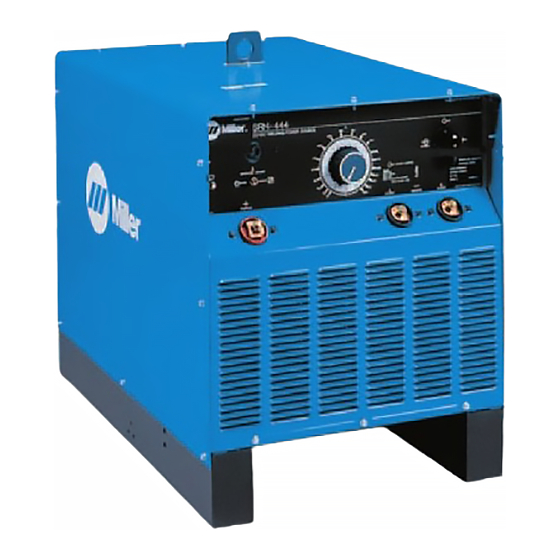
- Page 1 OM-2230T 2008-09 Processes Stick (SMAW) Welding Air Plasma Cutting and Gouging Air Carbon Arc (CAC-A) Cutting and Gouging Description Arc Welding Power Source SRH-444 OWNER'S MANUAL File : Stick (SMAW) Visit our website at www.MillerWelds.com...
- Page 2 We know you don’t have time to do it any other way. That’s why when Niels Miller first started building arc welders in 1929, he made sure his products offered long-lasting value and superior quality.
-
Page 3: Table Of Contents
TABLE OF CONTENTS SECTION 1 - SAFETY PRECAUTIONS – READ BEFORE USING......................1 1-1. Symbol Usage....................................1 1-2. Arc Welding Hazards..................................1 1-3. Additional Symbols For Installation, Operation, And Maintenance....................3 1-4. California Proposition 65 Warnings...............................4 1-5. Principal Safety Standards................................4 1-6. EMF Information....................................4 SECTION 2 - CONSIGNES DE SÉCURITÉ – LIRE AVANT UTILISATION....................5 2-1. Symboles utilisés..................................5 2-2. Dangers relatifs au soudage à... -
Page 5: Section 1 - Safety Precautions - Read Before Using
SECTION 1 - SAFETY PRECAUTIONS – READ BEFORE USING Protect yourself and others from injury - read and follow these precautions. 1-1. Symbol Usage ☞ Indicates special instructions. DANGER! - Indicates a hazardous situation which, if not avoided, will result in death or serious injury. The possible hazards are shown in the adjoining symbols or explained in the text. - Page 6 Watch for fire, and keep a fire extinguisher nearby. • HOT PARTS can cause severe burns. • Be aware that welding on a ceiling, floor, bulkhead, or partition Do not touch hot parts bare handed. can cause fire on the hidden side. •...
-
Page 7: Additional Symbols For Installation, Operation, And Maintenance
Never allow a welding electrode to touch any cylinder. • CYLINDERS can explode if damaged. • Never weld on a pressurized cylinder—explosion will result. Shielding gas cylinders contain gas under high Use only correct shielding gas cylinders, regulators, hoses, and •... -
Page 8: California Proposition 65 Warnings
Locate welding operation 100 meters from any sensitive • ARC WELDING can cause interference. electronic equipment. Electromagnetic energy can interfere with sensitive Be sure this welding machine is installed and grounded • • electronic equipment such as microprocessors, according to this manual. computers, and computer–driven equipment such If interference still occurs, the user must take extra measures •... -
Page 9: Section 2 - Consignes De Sécurité - Lire Avant Utilisation
SECTION 2 - CONSIGNES DE SÉCURITÉ – LIRE AVANT UTILISATION Se protéger et protéger les autres contre le risque de blessure ; lire et respecter ces consignes. 2-1. Symboles utilisés ☞ Fournit des instructions spéciales. DANGER ! - Indique une situation dangereuse qui, si elle n’est pas évitée, entraînera la mort ou des blessures graves. - Page 10 Porter un harnais de sécurité si l’on doit travailler au-dessus du • LES RAYONS D'ARC peuvent entraîner sol. des brûlures aux yeux et à la peau. S’assurer que tous les panneaux et couvercles sont • correctement en place. Le rayonnement de l’arc du procédé de soudage Fixer le câble de retour de façon à...
-
Page 11: Dangers Supplémentaires En Relation Avec L'installation, Le Fonctionnement Et La Maintenance
Avant de souder, retirer toute substance combustible de ses • LES BOUTEILLES peuvent exploser si elles poches telles qu’un allumeur au butane ou des allumettes. sont endommagées. Une fois le travail achevé, assurez-vous qu’il ne reste aucune • trace d’étincelles incandescentes ni de flammes. Des bouteilles de gaz protecteur contiennent du gaz Utiliser exclusivement des fusibles ou coupe-circuits appropriés. - Page 12 N’utiliser que les pièces de rechange recommandées par le • LES ÉTINCELLES VOLANTES risquent de constructeur. provoquer des blessures. LE RAYONNEMENT HAUTE Porter un écran facial pour protéger le visage et les • yeux. FRÉQUENCE (HF) risque de provoquer des interférences.
-
Page 13: Proposition Californienne 65 Avertissements
2-4. Proposition californienne 65 Avertissements Les équipements de soudage et de coupage produisent des Pour les moteurs à essence : fumées et des gaz qui contiennent des produits chimiques Les gaz d’échappement des moteurs contiennent des pro‐ dont l’État de Californie reconnaît qu'ils provoquent des mal‐ duits chimiques dont l’État de Californie reconnaît qu'ils pro‐... -
Page 14: Section 3 - Definitions
SECTION 3 - DEFINITIONS 3-1. Electric Shock And Airflow Label Warning! Watch Out! There are possible hazards as shown by the symbols. Electric shock from wiring and exposed weld terminals can kill. Close door before turning on unit. S179563 1/96 179 563 3-2. Nameplate Safety Symbols Warning! Watch Out! There are possible hazards as shown by... -
Page 15: Section 4 - Installation
SECTION 4 - INSTALLATION 4-1. Serial Number And Rating Label Location The serial number and rating information is located the front panel. Use rating label to determine input power requirements and/or rated output. For future reference, write serial number in space provided on back cover of this manual. 4-2. Specifications Rated Max OCV... -
Page 16: Volt-Ampere Curves
4-4. Volt-Ampere Curves Volt-ampere curves show minimum and maximum voltage and amperage output capabilities of unit. Curves of other settings fall between curves shown. 144 521-A 4-5. Selecting A Location Lifting Eye Lifting Forks Use lifting eye or lifting forks to move unit. -
Page 17: Dimensions And Weight
4-6. Dimensions and Weight Inches Millimeters 30-1/4 22-1/2 35-3/4 1-1/4 1-1/2 4-1/2 29-3/4 ½ in. Dia. (6 Holes) 13 mm Dia. (6 Holes) Weight 755 lb (342 (kg) ABC Dimensions / 800 039 Page 13... -
Page 18: Tipping
4-7. Tipping Do not move or operate unit where it could tip. Tipping 2 4-8. Selecting And Preparing Weld Output Cables Weld Output Cable Determine total cable length in weld circuit and maximum welding amperes. See Section 4-8 to select proper cable size. Use shortest cables possible. -
Page 19: Selecting Weld Cable Sizes
4-9. Selecting Weld Cable Sizes* Turn off power before connecting to weld output terminals. Do not use worn, damaged, undersized, or poorly spliced cables. Weld Cable Size** and Total Cable (Copper) Length in Weld Circuit Not Exceeding*** Welding 100 ft (30 m) or Less 150 ft (45 m) 200 ft (60 m) 250 ft (70 m) -
Page 20: Connecting To Weld Output Terminals
4-10. Connecting To Weld Output Terminals Turn off power before connecting to weld output terminals. Failure to properly connect weld cables may cause excessive heat and start a fire, or damage your machine. ☞ Do not place anything between weld cable terminal and copper bar. -
Page 21: Remote Amperage Control Receptacle
4-12. Remote Amperage Control Receptacle Remote Amperage Control Receptacle RC1 Keyway To connect remote amperage control to receptacle, insert plug and turn clockwise until tight. Ref. 802 927 Page 17... -
Page 22: Electrical Service Guide
4-13. Electrical Service Guide Input Voltage Input Amperes At Rated Output Max Recommended Standard Fuse Rating In Amperes Time Delay Fuse Normal Operating Fuse Min Input Conductor Size In AWG Max Recommended Input Conductor Length In Feet 171 (52) 142 (43) 375 (114) 395 (120) (Meters) -
Page 23: Connecting Input Power
4-14. Connecting Input Power A. Placing Jumper Links 208 VOLTS 230 VOLTS 460 VOLTS S 011 406 B 230 VOLTS 460 VOLTS 575 VOLTS S-094 120-B ☞ Tighten jumper link nuts to 25 in. lb ±5 Disconnect and lockout/tagout input Input Voltage Label - Only One Is On power before installing or moving Unit in. - Page 24 B. Connecting 3-Phase Input Power For Models With Customer-Supplied Cord = GND/PE Earth Ground = GND/PE Earth Ground 800 103-C / Ref. 801 116-A Page 20...
- Page 25 Installation must meet all National and Local Codes - have only qualified Welding Power Source Input Power Disconnect Device Input Power persons make this installation. Connections Connections Disconnect and lockout/tagout input 2 Strain Relief 7 Disconnect Device (switch shown in power before connecting input OFF position) conductors from unit.
-
Page 26: Section 5 - Operation
SECTION 5 - OPERATION 5-1. Controls ☞ Power Switch This amperage adjustment scale Supplementary Protector (Section 6-2) applies to the SMAW process only. If Use switch to turn unit On and Off. Remote Amperage Switch (Section using this machine for the GTAW 5-2) process, the scale does not apply. -
Page 27: Remote Amperage Switch
5-2. Remote Amperage Switch Max (100 A DC) Min (30 A DC) NOTICE - Arcing can damage switch. Do not For remote control, place switch in the Select Maximum Amperage change Remote Amperage switch position Remote position and connect remote Adjust Remote Amperage Control while power is on. -
Page 28: Section 6 - Maintenance
SECTION 6 - MAINTENANCE 6-1. Routine Maintenance Disconnect Power before maintaining. ✓ = Check ⃟ = Change ☼ = Clean ☆ = Replace Reference Every 3 Months ☆ Unreadable ☼ W eld Terminals Labels ✓☆ W eld Cables Every 6 Months ☼ Inside Unit ☼ Sealed Bearings - No Oil Needed... -
Page 29: Section 7 - Troubleshooting
SECTION 7 - TROUBLESHOOTING 7-1. Troubleshooting Trouble Remedy Place line disconnect switch in On position (see Section 4-14) Check and replace line fuse(s), if necessary, or reset circuit breaker (see Section 4-13). No weld output; unit completely inoperative. Check for proper input power connections (see Section 4-14). Check for proper jumper link position (see Section 4-14A). -
Page 30: Section 8 - Electrical Diagram
SECTION 8 - ELECTRICAL DIAGRAM ☞ For primary circuit diagram portion, refer to circuit diagram located inside wrapper of welding power source. Figure 8-1. Circuit Diagram 143 314-E Page 26... -
Page 31: Section 9 - Parts List
SECTION 9 - PARTS LIST ☞ Hardware is common and not available unless listed. Figure 9-1. Main Assembly OM-2230T Page 27... - Page 32 Item Dia. Part Mkgs. Description Quantity Figure 8-1. Main Assembly ......006016 ..Panel, Side ..2 ......006890 ..Cover, Top ..1 ..SR1 ..204171 ..Rectifier, Si Diode (400 Amp Model)(Eff W/Lb157023) ..1 ..SR2 ..
- Page 33 ☞ Hardware is common and not available unless listed. Figure 9-2. Panel, Front w/Components Item Dia. Part Mkgs. Description Quantity Figure 8-2 Panel, Front w/Components (Figure 8-1, Item 14) ......+202923..Panel, Front (Eff W/Lb157023) ..1 ..CB1 ..083432 ..Supplementary Protector, Man Rest 10A, 250 V Dc ..
- Page 34 ☞ Hardware is common and not available unless listed. Figure 9-3. Panel, Rear w/Components Item Dia. Part Mkgs. Description Quantity Figure 8-3. Panel, Rear w/Components ..FM ..237398 ..Motor, 1/12 Hp 230V 1550 Rpm 50/60 Hz ..1 ......124275 ..Chamber, Plenum 14 In..
- Page 35 Effective January 1, 2008 (Equipment with a serial number preface of LJ or newer) This limited warranty supersedes all previous Miller warranties and is exclusive with no other Warranty Questions? guarantees or warranties expressed or implied. Induction Heating Coils and Blankets, Cables, and LIMITED WARRANTY −...
- Page 36 Contact the Delivering Carrier to: File a claim for loss or damage during shipment. For assistance in filing or settling claims, contact your distributor and/or equipment manufacturer’s Transportation Department. © PRINTED IN USA 2008 Miller Electric Mfg. Co. 2008−01...