
Related Manuals for Miller Syncrowave 210


Summary of Contents for Miller Syncrowave 210
- Page 1 OM-261726G 2017-03 Processes Processes TIG (GTAW) Welding Stick (SMAW) Welding Description Syncrowave 210 File: TIG (GTAW) For product information, Owner’s Manual translations, and more, visit www.MillerWelds.com...
-
Page 2: Table Of Contents
..............6-1. Syncrowave 210 Controls . - Page 3 TABLE OF CONTENTS SECTION 8 − MAINTENANCE AND TROUBLESHOOTING ........8-1.
-
Page 5: Section 1 − Safety Precautions - Read Before Using
SECTION 1 − SAFETY PRECAUTIONS - READ BEFORE USING som 2015−09 Protect yourself and others from injury — read, follow, and save these important safety precautions and operating instructions. 1-1. Symbol Usage DANGER! − Indicates a hazardous situation which, if Indicates special instructions. - Page 6 D Remove stick electrode from holder or cut off welding wire at FUMES AND GASES can be hazardous. contact tip when not in use. D Wear body protection made from durable, flame−resistant material Welding produces fumes and gases. Breathing (leather, heavy cotton, wool). Body protection includes oil-free these fumes and gases can be hazardous to your clothing such as leather gloves, heavy shirt, cuffless trousers, high health.
-
Page 7: Additional Symbols For Installation, Operation, And Maintenance
1-3. Additional Symbols For Installation, Operation, And Maintenance FIRE OR EXPLOSION hazard. MOVING PARTS can injure. D Do not install or place unit on, over, or near D Keep away from moving parts such as fans. combustible surfaces. D Keep all doors, panels, covers, and guards D Do not install unit near flammables. -
Page 8: California Proposition 65 Warnings
1-4. California Proposition 65 Warnings Welding or cutting equipment produces fumes or gases This product contains chemicals, including lead, known to which contain chemicals known to the State of California to the state of California to cause cancer, birth defects, or other cause birth defects and, in some cases, cancer. -
Page 9: Section 2 − Consignes De Sécurité − Lire Avant Utilisation
SECTION 2 − CONSIGNES DE SÉCURITÉ − LIRE AVANT UTILISATION fre_som_2015−09 Pour écarter les risques de blessure pour vous−même et pour autrui — lire, appliquer et ranger en lieu sûr ces consignes relatives aux précautions de sécurité et au mode opératoire. 2-1. - Page 10 chauffement ou un incendie. Avant de commencer le soudage, vérifier LES PIÈCES CHAUDES peuvent et s’assurer que l’endroit ne présente pas de danger. provoquer des brûlures. D Déplacer toutes les substances inflammables à une distance de D Ne pas toucher à mains nues les parties chaudes. 10,7 m de l’arc de soudage.
-
Page 11: Dangers Supplémentaires En Relation Avec L'installation, Le Fonctionnement Et La Maintenance
D Tenir les bouteilles éloignées des circuits de soudage ou autres LE BRUIT peut endommager l’ouïe. circuits électriques. D Ne jamais placer une torche de soudage sur une bouteille à gaz. Le bruit des processus et des équipements peut affecter l’ouïe. D Une électrode de soudage ne doit jamais entrer en contact avec D Porter des protections approuvées pour les une bouteille. -
Page 12: Proposition Californienne 65 Avertissements
RAYONNEMENT HAUTE LE SOUDAGE À L’ARC risque de FRÉQUENCE (H.F.) risque provoquer des interférences. provoquer des interférences. D L’énergie électromagnétique risque D Le rayonnement haute fréquence (H.F.) peut provoquer des interférences pour l’équipement provoquer des interférences avec les équi- électronique sensible tel que les ordinateurs et l’équipement commandé... -
Page 13: Section 3 − Definitions
A complete Parts List is available at www.MillerWelds.com SECTION 3 − DEFINITIONS 3-1. Additional Safety Symbols And Definitions Warning! Watch Out! There are possible hazards as shown by the symbols. Safe1 2012−05 Do not move or operate unit where it could tip. Safe 113 2013−04 3-2. -
Page 14: Section 4 − Specifications
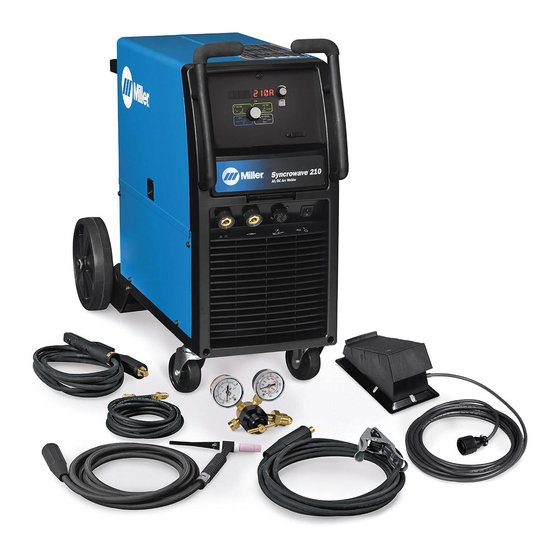
A complete Parts List is available at www.MillerWelds.com SECTION 4 − SPECIFICATIONS 4-1. Included with Your Unit 12 ft (3.7 m) Work Cable With Clamp And Quick-Connect WP1712SFDI 150 Amp TIG Torch with 12 ft (3.7 m) Cable And Quick-Connect Electrode Holder and Quick-Connect Gas Hose... -
Page 15: Specifications
A complete Parts List is available at www.MillerWelds.com 4-3. Specifications Do not use information in unit specifications table to determine electrical service requirements. See Sections 5-8, 5-10 and/or 5-11 for information on connecting input power. This equipment will deliver rated output at an ambient air temperature up to 1045F (405C). Welding Input Amperage... -
Page 16: Duty Cycle Chart
A complete Parts List is available at www.MillerWelds.com 4-5. Duty Cycle Chart Duty cycle is percentage of 10 TIG - 230 VAC minutes that unit can weld at rated load without overheating. NOTICE − Exceeding duty cycle can damage unit and void warranty. Stick - 230 VAC TIG - 115 VAC Stick - 115 VAC... -
Page 17: Section 5 − Installation
A complete Parts List is available at www.MillerWelds.com SECTION 5 − INSTALLATION 5-1. Selecting A Location Movement Do not move or operate unit where it could tip. Location And Airflow Special installation may be required where gasoline or volatile liquids are present − see NEC Article 511 or CEC Section 20. -
Page 18: Remote 14 Receptacle
A complete Parts List is available at www.MillerWelds.com 5-2. Remote 14 Receptacle Socket* Socket Information 15 volts DC. Contact closure to A completes 15 volts DC contactor control circuit. Command reference; 0 to +10 volts DC output to remote control. Remote control circuit common. -
Page 19: Shielding Gas Connections
A complete Parts List is available at www.MillerWelds.com 5-3. Shielding Gas Connections Use argon shielding gas for best performance. Cylinder Valve Tools Needed: Open valve slightly so gas flow blows dirt from valve. Close valve. 5/8, 1-1/8 in. Regulator/Flow Gauge Connect regulator/flow gauge to gas cylinder. -
Page 20: Removing Power Pin Style Connector To Adapt Spoolmate 100/150 Models For Use With
A complete Parts List is available at www.MillerWelds.com 5-5. Removing Power Pin Style Connector To Adapt Spoolmate 100/150 Models For Use With The Syncrowave 210 Turn Off welding power source and disconnect spool gun. Photo 1 −Power Pin Style Connector... -
Page 21: Adapter Cord Connections To Adapt Spoolmate 100/150 Models For Use With The Syncrowave 210
A complete Parts List is available at www.MillerWelds.com 5-7. Adapter Cord Connections To Adapt Spoolmate 100/150 Models For Use With The Syncrowave 210 Turn welding power source before connecting adapter cable. 4 To 14-Pin Adapter 14-Pin Receptacle Insert spool gun control cable 4-pin plug into matching receptacle on 4-pin adapter cord and tighten collar. -
Page 22: Connecting 115 Volts Input Power
A complete Parts List is available at www.MillerWelds.com 5-9. Selecting Extension Cord (Use Shortest Cord Possible) Conductor Size − AWG (mm Single Phase AC 4 (21.2) 6 (13.3) 8 (8.4) 10 (5.3) 12 (3.3) Input Voltage Maximum Allowable Cord Length in ft (m) 160 (49) 107 (33) 71 (22) - Page 23 A complete Parts List is available at www.MillerWelds.com Notes OM-261726 Page 19...
-
Page 24: Connecting 1-Phase Input Power
A complete Parts List is available at www.MillerWelds.com 5-11. Connecting 1-Phase Input Power =GND/PE Earth Ground 230 VAC, 1 Tools Needed: input4 2012−05 − Ref. 803766-C / Ref. 805519-A / Ref. 805540-A OM-261726 Page 20... - Page 25 A complete Parts List is available at www.MillerWelds.com 5-11. Connecting 1-Phase Input Power (Continued) See rating label on unit and check input volt- Over-Current Protection Installation must meet all National and age available at site. Local Codes − have only qualified per- Select type and size of over-current protec- sons make this installation.
-
Page 26: Multi−Voltage Plug (Mvp) Connection
A complete Parts List is available at www.MillerWelds.com 5-12. Multi−Voltage Plug (MVP) Connection Selecting Plug Do not cut off power cord con- nector and rewire. The power cord connector and plugs will work with standard NEMA re- ceptacles. Modifying power cord, connector, and plugs will void product warranty. -
Page 27: Section 6 − Operation
A complete Parts List is available at www.MillerWelds.com SECTION 6 − OPERATION 6-1. Syncrowave 210 Controls 268890-B/ 805521-A Amperage Adjustment Control Volt Meter Output ON Indicator Displays actual voltage when voltage is Blue indicator illuminates when output is Use control to change preset amperage present at the weld output terminals. -
Page 28: Accessing Control Panel Menu: Ac Tig
A complete Parts List is available at www.MillerWelds.com 6-2. Accessing Control Panel Menu: AC TIG Menu Button Press Menu button to cycle through parameters that can be set. Parameter Display Setting Display Encoder Rotate Encoder to adjust parameter setting. 150A 268890-B Amperage Control: 150A... -
Page 29: Accessing Dc Tig Control Panel Menu
A complete Parts List is available at www.MillerWelds.com 6-3. Accessing DC TIG Control Panel Menu Menu Button Press Menu button to cycle through parameters that can be set. Parameter Display Setting Display Encoder Rotate Encoder to adjust parameter setting. Amperage Control: Controls the welding amper- 150A age output. -
Page 30: Accessing Spool Gun Control Panel Menu
A complete Parts List is available at www.MillerWelds.com 6-5. Accessing Spool Gun Control Panel Menu Menu Button Press Menu button to cycle through parameters that can be set. Parameter Display Setting Display Encoder Rotate Encoder to adjust parameter setting. 14.0V Voltage Control: Controls the welding voltage output. -
Page 31: Accessing User Setup Menu: Ac And Dc Tig
A complete Parts List is available at www.MillerWelds.com 6-6. Accessing User Setup Menu: AC And DC TIG Menu Button Press and hold Menu button for approxim- ately two seconds to access machine config- uration menus. Use Menu button to cycle through parameters that can be set. -
Page 32: Accessing User Dc Stick Setup Menu
A complete Parts List is available at www.MillerWelds.com 6-7. Accessing User DC Stick Setup Menu Menu Button Press and hold Menu button for ap- proximately 2 seconds to access machine configuration menus. Use Menu button to cycle through para- meters that can be set. Parameter Display Setting Display Encoder... -
Page 33: Accessing User Spool Gun Setup Menu
A complete Parts List is available at www.MillerWelds.com 6-8. Accessing User Spool Gun Setup Menu Menu Button Press and hold Menu button for ap- proximately two seconds to access machine configuration menus. Use Menu button to cycle through para- meters that can be set. Parameter Display Setting Display Encoder... -
Page 34: Section 7 − Advanced Menu Functions
A complete Parts List is available at www.MillerWelds.com SECTION 7 − ADVANCED MENU FUNCTIONS 7-1. Accessing Tech Menu Menu Button Press and hold Menu button for ap- proximately 4 seconds to scroll past User Menu to Tech Menu. Use Menu button to cycle through para- meters that can be set. -
Page 35: Section 8 − Maintenance And Troubleshooting
A complete Parts List is available at www.MillerWelds.com SECTION 8 − MAINTENANCE AND TROUBLESHOOTING 8-1. Routine Maintenance Disconnect power before maintaining. Maintain more often during severe conditions. n = Check Z = Change ~ = Clean Δ = Repair l = Replace * To be done by Factory Authorized Service Agent Every Months... -
Page 36: Meter Troubleshooting Displays
A complete Parts List is available at www.MillerWelds.com 8-3. Meter Troubleshooting Displays ..2 Sec RELE TRIG Repeat Over Temperature Errors: w [PFC] [ERRT] All directions are in reference to the front of the unit. All circuitry referred to Indicates a short or open in the thermal pro- w [INV] [OT] is located inside the unit. -
Page 37: Troubleshooting
A complete Parts List is available at www.MillerWelds.com 8-4. Troubleshooting The remedies listed below are recommendations only. If these remedies do not fix the trouble with your unit, have a Factory Authorized Service Agent check unit. There are no user serviceable parts inside unit. Trouble Remedy No weld output;... - Page 38 A complete Parts List is available at www.MillerWelds.com Trouble Remedy Error message [INV] [ERRT] Contact a Factory Authorized Service Agent. displayed. Error message [PFC] [ERRT] Contact a Factory Authorized Service Agent. displayed. Error message [SEC] [ERRT] Contact a Factory Authorized Service Agent. displayed.
- Page 39 A complete Parts List is available at www.MillerWelds.com Notes OM-261726 Page 35...
-
Page 40: Section 9 − Electrical Diagrams
A complete Parts List is available at www.MillerWelds.com SECTION 9 − ELECTRICAL DIAGRAMS 262672-D Figure 9-1. Circuit Diagram OM-261726 Page 36... -
Page 41: Section 10 − High Frequency
SECTION 10 − HIGH FREQUENCY 10-1. Welding Processes Requiring High Frequency High-Frequency Voltage TIG − helps arc jump air gap between torch and workpiece and/ or stabilize the arc. Work high_freq 5/10 − S-0693 10-2. Installation Showing Possible Sources Of HF Interference Weld Zone 11, 12 50 ft... -
Page 42: Recommended Installation To Reduce Hf Interference
10-3. Recommended Installation To Reduce HF Interference Weld Zone 50 ft (15 m) 50 ft (15 m) Ground all metal ob- jects and all wiring in welding zone using #12 AWG wire. Ground workpiece if required by Nonmetal codes. Building Best Practices Followed Metal Building Ref. -
Page 43: Section 11 − Selecting And Preparing A Tungsten
SECTION 11 − SELECTING AND PREPARING A TUNGSTEN FOR DC OR AC WELDING WITH INVERTER MACHINES gtaw_Inverter_2016-10 Whenever possible and practical, use DC weld output instead of AC weld output. 11-1. Selecting Tungsten Electrode ( Wear Clean Gloves To Prevent Contamination Of Tungsten Not all tungsten electrode manufacturers use the same colors to identify tungsten type. -
Page 44: Section 12 − Guidelines For Tig Welding (Gtaw)
SECTION 12 − GUIDELINES FOR TIG WELDING (GTAW) 12-1. Positioning The Torch Grinding the tungsten electrode produces dust and flying sparks which can cause injury and start fires. Use local exhaust (forced ventilation) at the grinder or wear an approved respirator. Read MSDS for safety information. -
Page 45: Torch Movement During Welding
12-2. Torch Movement During Welding Tungsten Without Filler Rod ° Welding direction Form pool Tilt torch Move torch to front of pool. Repeat process. Tungsten With Filler Rod ° ° Welding direction Form pool Tilt torch Add filler metal Remove rod Move torch to front of pool. -
Page 46: Section 13 − Stick Welding (Smaw) Guidelines
SECTION 13 − STICK WELDING (SMAW) GUIDELINES 13-1. Stick Welding Procedure Weld current starts when electrode touches work- piece. Weld current can damage electronic parts in vehicles. Disconnect both battery Equipment Needed: Tools Needed: cables before welding on a vehicle. Place work clamp as close to the weld as possible. -
Page 47: Electrode And Amperage Selection Chart
13-2. Electrode and Amperage Selection Chart 6010 DEEP 3/32 MIN. PREP, ROUGH HIGH SPATTER 6011 DEEP 6010 5/32 & 6013 EP,EN GENERAL 3/16 6011 7/32 SMOOTH, EASY, 7014 EP,EN FAST 1/16 LOW HYDROGEN, 7018 5/64 STRONG 3/32 FLAT SMOOTH, EASY, 7024 EP,EN 6013... -
Page 48: Positioning Electrode Holder
13-4. Positioning Electrode Holder End View Of Work Angle Side View Of Electrode Angle After learning to start and hold an arc, practice running beads of weld metal on flat plates using a full electrode. ° ° Hold the electrode nearly per- pendicular to the work, although tilting it ahead (in the direction of °... -
Page 49: Conditions That Affect Weld Bead Shape
13-7. Conditions That Affect Weld Bead Shape Weld bead shape is affected electrode angle, length, travel speed, and thick- ness of base metal. Correct Angle Angle Too Large ° - ° Angle Too Small Electrode Angle Drag Spatter Arc Length Normal Too Long Too Short... - Page 50 13-10. Welding Groove (Butt) Joints Tack Welds Prevent butt joint distortion by tack welding the materials in position before final weld. Workpiece distortion occurs when heat is applied locally to a joint. One side of a metal plate will “curl” up toward the weld.
-
Page 51: Weld Test
13-12. Weld Test Vise Weld Joint Hammer Strike the weld joint in the direction shown. A good weld bends over but does not break. If the weld breaks, examine it to determine the cause. If the weld is porous (many holes), the arc length was probably too long. - Page 52 Lack Of Penetration − shallow fusion between weld metal and base metal. Lack of Penetration Good Penetration Possible Causes Corrective Actions Improper joint preparation. Material too thick. Joint preparation and design must provide access to bottom of groove. Improper weld technique. Keep arc on leading edge of weld puddle.
- Page 55 Effective January 1, 2017 (Equipment with a serial number preface of MH or newer) This limited warranty supersedes all previous Miller warranties and is exclusive with no other guarantees or warranties expressed or implied. Warranty Questions? LIMITED WARRANTY − Subject to the terms and conditions below, 6 Months —...
- Page 56 Contact the Delivering Carrier to: File a claim for loss or damage during shipment. For assistance in filing or settling claims, contact your distributor and/or equipment manufacturer’s Transportation Department. © ORIGINAL INSTRUCTIONS − PRINTED IN USA 2017 Miller Electric Mfg. Co. 2017−01...