Table of Contents
Advertisement
604D- - - - A
LEGACYt 13 SEER
SINGLE- - PACKAGED HEAT PUMP SYSTEM
WITH PURONR (R- - 410A) REFRIGERANT
SINGLE AND THREE PHASE
NOMINAL 2- - 5 TONS (SIZES 24- - 60)
NOTE:
Read the entire instruction manual before starting the
installation.
NOTE:
Installer: Make sure the Owner's Manual and Service
Instructions are left with the unit after installation.
TABLE OF CONTENTS
SAFETY CONSIDERATIONS
. . . . . . . . . . . . . . . . . . . . . . . . . . . . . . . . . . .
. . . . . . . . . . . . . . . . . . . . . . . . . . . . . . . . . .
. . . . . . . . . . . . . . . . . . . . . . . . . . . . . . . . . . . .
. . . . . . . . . . . . . . . . . . . . . . . . . . . . . . . . .
. . . . . . . . . . . . . . . . . . . . . . . . . . . . . . .
. . . . . . . . . . . . . . . . . . . . . . . . . . . . . . . . . . . . . .
. . . . . . . . . . . . . . . . . . . . . . . . . . . . . . . . . . . . .
. . . . . . . . . . . . . . . . . . . . . . . . . . . . . . . . .
. . . . . . . . . . . . . . . . . . . . . . . . . . . . . . . . .
. . . . . . . . . . . . . . . . . . . . . . . . . . . . . . . . . . . . . .
. . . . . . . . . . . . . . . . . . . . . . . . . . . .
. . . . . . . . . . . . . . . . . . . . . . . . . . . .
. . . . . . . . . . . . . . . . . . . . . . . . . . .
. . . . . . . . . . . . . . . . . . . . . . . . . . . . . . . . . . .
. . . . . . . . . . . . . . . . . . . . . . . . . . . . . . . . . . . . .
. . . . . . . . . . . . . . . . . . . . . . . . . . . . .
. . . . . . . . . . . . . . . . . . . . . . . . . . . . . . . . . . .
. . . . . . . . . . . . . . . . . . . . . . . . . . . . . . . . . . . . .
. . . . . . . . . . . . . . . . . . . . . . . . . . . . . . . . . . . . . . .
. . . . . . . . . . . . . . . . . . . . . . . . . . . . . . . .
. . . . . . . . . . . . . . . . . . . . . . . . . . . . . . . . . . . . . . . .
. . . . . . . . . . . . . . . . . . . . . . . . . . .
. . . . . . . . . . . . . . . . . . . . . . . . . . . . . . . . . . . . .
. . . . . . . . . . . . . . . . . . . . . . . . . . . . . . . . .
. . . . . . . . . . . . . . . . . . . . . . . . . . . . . . . . . . .
. . . . . . . . . . . . . . . . . . . . . . . . . . . . . . . . .
. . . . . . . . . . . . . . . . . . . . . . . . . . . . .
. . . . . . . . . . . . . . . . . . . . . . . . . . . . . .
. . . . . . . . . . . . . . . . . . . . . . . . . . . . . . . .
Installation Instructions
. . . . . . . . . . . . . . . . . . . . . . .
. . . . . . . . . . . . . . . . .
. . . . . . . . . . . . . . . . . . . . . . . . . . .
. . . . . . . . . . . . . . . . . . . . . . . . . .
. . . . . . . . . . . . . . . . . . . . . .
. . . . . . . . . . . . . . . . . . . . . . . . .
. . . . . . . . . . . . . . . . . . . . . . . . .
. . . . . . . . . . . . . .
. . . . . . . . . . . . . . . . . . . . . . .
. . . . . . . . . . . . . . .
. . . . . . . .
. . . . . . . . . . . . . . . . . . . . . . . . .
. . . . . . . . . . . . . . . . . . .
. . . . . . . . . . . .
. . . . . . . . . . . . . .
. . . . . . . . . . . . . . . . . . . . . . . .
. . . . . .
. . . . . . . . . . . . . . . . . . . . . . .
. . . . . . . . . . . . . . . . . . . .
. . . . . . . . .
PAGE
1- -2
2
2- -10
2
2
2
2
2
2
2
3
3
7
7
8
9
9
9
10
10
10
10
10
18
18- -22
. . . . . . . . . . . . . . . . . . . . . . . . . . . . . . . . . . . . . . . . .
18
. . . . . . . . . . . . . . . . . . . . . . . . . . . . . . . . . . . . . .
18
. . . . . . . . . . . . . . . . . . . . . . . . . . . . . . . . . . . . . .
18
19
19
19
. . . . . . . . . . . . . . . . . . . . . . . . . . . . . . . . . . . . . .
20
22
SAFETY CONSIDERATIONS
22
22
Installation and servicing of this equipment can be hazardous due
22- -28
to mechanical and electrical components. Only trained and
22
qualified personnel should install, repair, or service this equipment.
22
Untrained personnel can perform basic maintenance functions such
23
as cleaning and replacing air filters. All other operations must be
23
performed by trained service personnel. When working on this
26
equipment, observe precautions in the literature, on tags, and on
26
labels attached to or shipped with the unit and other safety
27
precautions that may apply.
27
Follow all safety codes. Wear safety glasses, protective clothing,
27
and work gloves. Use quenching cloth for brazing operations.
27
Have a fire extinguisher available. Read these instructions
27
thoroughly and follow all warnings or cautions included in
27
literature and attached to the unit. Consult local building codes, the
27
current editions of the National Electrical Code (NEC) NFPA 70.
1
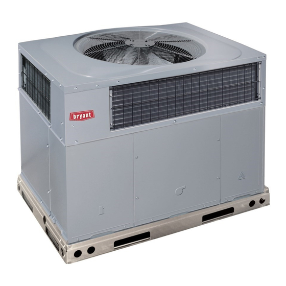
Fig. 1 - - Unit 604D- -- -A
. . . . . . . . . . . . . . . . . . . . . . . . . . . . . . . . . . . .
. . . . . . . . . . . . . . . . . . . . . . . . . . . . . . . . .
. . . . . . . . . . . . . . . . . . . . . . . . . . .
. . . . . . . . . . . . .
. . . . . . . . . . . . . . . . . . . . . . . . . . . . . . . .
. . . . . . . . . . . . . . . . . . . . . . . . . . . .
. . . . . . . . . . . . . . . . . . . . . . . . .
. . . . . . . . . . . . . . . . . . . . . . . . . . . . . .
. . . . . . . . . . . . . . . . . . . . . . . . . . . .
. . . . . . . . . . . . . . . . . . . . . . .
. . . . . . . . . . . . . . . . . . . . . . . . . . . . . . .
. . . . . . . . . . . . . . . . . . . . . . . . . . . . . . .
. . . . . . . . . . . . . . . . . . . . . . . . . . . . . .
. . . . . . . . . . . . . . . . . . . . . . . . . . . . . .
A09034
27
27
. . . .
27
28
28
28
28
28
28
28
32- -50
32
32
32
32- -33
36- -38
39- -48
49
50
Advertisement
Table of Contents
Troubleshooting

Related Manuals for Bryant LEGACY 604D-A


Summary of Contents for Bryant LEGACY 604D-A
-
Page 1: Table Of Contents
604D- - - - A LEGACYt 13 SEER SINGLE- - PACKAGED HEAT PUMP SYSTEM WITH PURONR (R- - 410A) REFRIGERANT SINGLE AND THREE PHASE NOMINAL 2- - 5 TONS (SIZES 24- - 60) Installation Instructions NOTE: Read the entire instruction manual before starting the installation. -
Page 2: Introduction
INTRODUCTION The 604D- -- -A heat pump is fully self- -contained and designed for outdoor installation. (See Fig. 1.) Standard units are shipped in a horizontal- -discharge configuration groundlevel slab. -
Page 3: Rig And Place Unit
under a partial overhang (such as a normal house overhang) is 48 in. (1219 mm) above the unit top. The maximum horizontal extension of a partial overhang must not exceed 48 in. (1219 mm). IMPORTANT: Do not restrict outdoor airflow. An air restriction at either the outdoor- -air inlet or the fan discharge may be detrimental to compressor life. - Page 4 A09471 Fig. 2 - - 604D- -- -A24- -36 Unit Dimensions...
- Page 5 A09472 Fig. 3 - - 604D- -- -A42- -60 Unit Dimensions...
- Page 6 HVAC unit HVAC unit basepan base rails Anchor screw Flashing field supplied Roofing material field supplied Cant strip field supplied *Provided with roofcurb ROOF CURB DETAIL LARGE CURB UNIT CATALOG SIZE NUMBER IN. (mm) Small CPRFCURB010A00 11 (279) CPRFCURB011A00 14 (356) Large CPRFCURB012A00 11 (279)
-
Page 7: Rigging/Lifting Of Unit
CAUTION - NOTICE TO RIGGERS PRUDENCE - AVIS AUX MANIPULATEUR ACCESS PANELS MUST BE IN PLACE WHEN RIGGING. PANNEAUX D'ACCES DOIT ÊTRE EN PLACE POUR MANIPULATION. Use top skid as spreader bar. / Utiliser la palette du haut comme barre de répartition SEE DETAIL A VOIR DÉTAIL A CORNER WEIGHTS (SMALL CABINET) -
Page 8: Converting Horizontal Discharge Units To Downflow (Vertical) Discharge Units
WARNING PERSONAL INJURY OPERATION HAZARD Failure to follow this warning could result in personal injury or death. For vertical supply and return units, tools or parts could drop into ductwork Install a 90 degree turn in the return ductwork between the unit and the conditioned space. If a 90 degree elbow cannot be installed, then a grille of sufficient strength and density should be installed to prevent objects from falling into the conditioned space. -
Page 9: Provide For Condensate Disposal
Step 6 — Provide for Condensate Disposal NOTE: Ensure that condensate- -water disposal methods comply with local codes, restrictions, and practices. The 604D- -- -A units dispose of condensate through a 3/4 in. NPT female fitting that exits on the compressor end of the unit. Condensate water can be drained directly onto the roof in rooftop installations (where permitted) or onto a gravel apron in ground level installations. -
Page 10: Special Procedures For 208- -V Operation
Special Procedures for 208- - V Operation WARNING ELECTRICAL SHOCK HAZARD Failure to follow this warning could result in personal injury or death. Before installing or servicing system, always turn off main power to system and install lockout tag. With disconnect switch open, move black wire from transformer (3/16 in.) terminal marked 230 to terminal marked 200. - Page 11 UNIT SIZE NOMINAL CAPACITY (ton) SHIPPING WEIGHT} (lb) (kg) COMPRESSOR QUANTITY TYPE REFRIGERANT Refrigerant (R --- 410A) Quantity (lb) Quantity (kg) METERING DEVICE ID ORIFICE OD (in.) (mm) OUTDOOR COIL Rows... Fins/in. face area (sq. ft.) OUTDOOR FAN Nominal Airflow (CFM) Diameter Motor HP (RPM) INDOOR COIL Rows...
- Page 12 A10197 Fig. 11 - - Connection Wiring Schematics 208/230- -1- -60...
- Page 13 A10197 Fig. 11 Cont. - - Ladder Wiring Schematics 208/230- -1- -60...
- Page 14 A10194 Fig. 12 - - Connection Wiring Schematics - - 208/230- -3- -60...
- Page 15 A10194 Fig. 12 Cont. - - Ladder Wiring Schematics - - 208/230- -3- -60...
- Page 16 A10195 Fig. 13 - - Connection Wiring Diagram 460- -3- -60...
- Page 17 A10195 Fig. 13 Cont. - - Ladder Wiring Diagram 460- -3- -60...
-
Page 18: Pre- -Start- -Up
5 minutes have elapsed. The defrost board has a built- -in 5 minute delay between cycles. The 5 minute compressor delay also applies to heat pump heating mode. Step 1 — Check for Refrigerant Leaks... -
Page 19: A Sequence Of Operation
(1.) Thermostat closes circuits R to G and R to Y. The compressor, indoor and outdoor fans are energized. e. HEAT PUMP HEATING WITH AUXILIARY ELECTRIC HEAT (1.) Thermostat closes circuits R to G, R to Y and R to W/W1 or W2. -
Page 20: Continuous Fan Operation
Two Cooling Fan Speeds Set-up (Dehumidification feature used) IMPORTANT: Dehumidification control must open control circuit on humidity rise above set point. Use of the dehumidification cooling fan speed requires use of either a 24 VAC dehumidistat or a thermostat which includes control of a 24 VAC dehumidistat connection. - Page 21 LCS – Loss of Charge Switch Accurater ® Metering De vice Arrow indicates direction of flo w Fig. 14 - - Typical Heat Pump Operation, Cooling Mode HIGH D5 D3 SSTZ-8 Fig. 15 - - Interface Fan Board (IFB) OUTDOOR COIL...
-
Page 22: Defrost Control
To ensure continuing high performance, and to minimize the possibility of premature equipment failure, periodic maintenance must be performed on this equipment. This heat pump unit should be inspected at least once each year by a qualified service person. To troubleshoot unit, refer to Table 9. -
Page 23: Outdoor Coil, Indoor Coil, & Condensate Drain Pan
WARNING ELECTRICAL SHOCK HAZARD Failure to follow this warning could result in personal injury or death. Disconnect and install lockout tag on electrical power to the unit before cleaning and lubricating the blower motor and wheel. To clean the blower motor and wheel: 1. - Page 24 Table 4 – Dry Coil Air Delivery* - - Horizontal and Downflow Discharge - - Unit 604D- -- -A24- -60 Series A MOTOR UNIT SPEED COLOR Med---Low 604D --- ---A24 Medium Med---High Orange High Med---Low 604D --- ---A30 Medium Med---High Orange High Med---Low...
- Page 25 A09070 Fig. 17 - - Cooling Charging Table- -Subcooling...
-
Page 26: Electrical Controls And Wiring
Speedup Quiet Pins Shift Step 4 — Electrical Controls and Wiring Inspect and check the electrical controls and wiring annually. Be sure to turn off the electrical power to the unit. Remove access panels (see Fig. 20) to locate all the electrical controls and wiring. -
Page 27: Indoor Airflow
BLOWER ACCESS COMPRESSOR PANEL ACCESS PANEL Fig. 20 - - Unit Access Panels Step 6 — Indoor Airflow The heating and/or cooling airflow does not require checking unless improper performance is suspected. If a problem exists, be sure that all supply- -air and return- -air grilles are open and free from obstructions, and that the air filter is clean. -
Page 28: Liquid Line Filter Drier
Check Defrost Thermostat The defrost thermostat signals heat pump that conditions are right for defrost or that conditions have changed to terminate defrost. It is a thermally actuated switch clamped to outdoor coil to sense its temperature. - Page 29 PURONR (R- -410A) QUICK REFERENCE GUIDE Puron refrigerant operates at 50- -70 percent higher pressures than R- -22. Be sure that servicing equipment and replacement components are designed to operate with Puron Puron refrigerant cylinders are rose colored. Recovery cylinder service pressure rating must be 400 psig, DOT 4BA400 or DOT BW400. Puron systems should be charged with liquid refrigerant.
- Page 30 SYMPTOM Compressor and condenser fan will not start. Compressor will not start but condenser fan runs Three- -phase scroll compressor makes excessive noise, and there may be a low pressure differential. Compressor cycles (other than normally sat- isfying thermostat). Compressor operates continuously Excessive head pressure Head pressure too low Excessive suction pressure...
- Page 31 COMPRESSOR AMPS INDOOR (EVAPORATOR) FAN AMPS TEMPERATURES OUTDOOR (CONDENSER) AIR TEMPERATURE RETURN- -AIR TEMPERATURE COOLING SUPPLY AIR HEAT PUMP SUPPLY AIR __________________ ELECTRIC HEAT SUPPLY AIR_______________ PRESSURES REFRIGERANT SUCTION REFRIGERANT DISCHARGE ( ) VERIFY REFRIGERANT CHARGE USING CHARGING CHARTS * Measured at suction inlet to compressor { Measured at liquid line leaving condenser.
-
Page 32: Vertical Economizer
Space Temperature and CO Sensor with Override (4--- 20mA) Space Temperature and CO Sensor with Override and Set Point Heat Pump Relay Package Small Chassis To install the Vertical Economizer on the small chassis perform the following procedure: 1. Turn off unit power supply and install lockout tag. - Page 33 OAT Sensor Fig. 22 - - Economizer Hood Top Panel Removal OAT Sensor Fig. 23 - - Oat Sensor Installed 6. Replace horizontal return duct cover panel. Screw in place ensuring all seams are air and watertight. 7. Install the 2 angle filter brackets to the right and left hood side panels respectively with the #10 screws provided.
- Page 34 Hood Divider Horizontal Return Duct Cover Panel Fig. 24 - - Horizontal Return Duct Cover Panel Removal Left Hood Side Panel Filter Angle Bracket Fig. 25 - - Filter Angle Bracket Installation Hood Divider (Removed) Filter Angle Bracket A09691 Right Hood Side Panel A09692...
- Page 35 Hood Top Panel Hood Divider Left Hood Side Panel Fig. 26 - - Economizer Hood Assembly Fig. 27 - - Economizer Hood Installation Right Hood Side Panel A09694 Fig. 28 - - Filter Installation (See Through View) A09693 Filter Clips Aluminum Filter A09695...
-
Page 36: Large Chassis
Large Chassis To install the Vertical Economizer on the large chassis perform the following procedure: 1. Turn off unit power supply and install lockout tag. WARNING ELECTRICAL SHOCK HAZARD Failure to follow this warning could result in personal injury or death. Before installing or servicing system, always turn off main power to system and install lockout tag. - Page 37 Fig. 31 - - OAT Bracket Installation Left Hood Side Panel Filter Angle Bracket Left Hood Side Fig. 32 - - Filter Angle Bracket Installation Right Hood Side Panel Filter Angle Bracket Right Hood Side A09698 A09699...
- Page 38 Hood Top Panel Left Hood Side Panel Fig. 34 - - Economizer Hood Installation 11. Open the filter clips on the inside of the hood top. Insert the aluminum filter into the hood and close the clips to hold in place.
-
Page 39: Configuration
Aluminum Filter Fig. 35 - - Filter Installation (See through view) Top filter rack Evaporator Coil Screw (Note 4 and 5) Bottom filter rack BENT COIL Top filter rack Bottom filter rack STRAIGHT COIL Fig. 36 - - Indoor Coil with Filter Rack CONFIGURATION Economizer Standard Sensors OUTDOOR AIR TEMPERATURE (OAT) SENSOR—... - Page 40 TEMPERATURE COMPRESSOR SWITCH—The Economizer is equipped with a low ambient temperature lockout switch located in the outdoor airstream which is used to lock out the compressors below a 42_F (5.6_C) ambient temperature. Economizer Control Modes—Determine the Economizer control mode before set up of the control. Some modes of operation may require different sensors.
- Page 41 CONTROL CONTROL POINT CURVE APPROX ˚F (˚C) AT 50% RH (27) 73 (23) 70 (21) 67 (19) 63 (17) (24) (21) (18) (16) (13) (10) (10) (13) (16) (18) (21) (24) APPROXIMATE DRY BULB TEMPERATURE — ˚F (˚C) Fig. 41 - - Enthalpy Changeover Setpoints 6000 5000 4000...
- Page 42 When demand ventilation control is not being used, the minimum position potentiometer should be used to set the occupied ventilation position. The maximum demand ventilation position should be turned fully clockwise. Adjust the minimum position potentiometer to allow the minimum amount of outdoor air, as required by local codes, to enter the building.
- Page 43 A10059 Fig. 44 - - Economizer Wiring Diagram...
- Page 44 DANGER: ELECTRICAL SHOCK HAZARD DISCONNECT POWER BEFORE SERVICING NOTES: 1. IF ANY OF THE ORIGINAL WIRES FURNISHED ARE REPLACED, THEY MUST BE REPLACED WITH THE SAME WIRE OR ITS EQUIVALENT. 2. SEE PRICE PAGES FOR THERMOSTATS. 3. USE 75 DEG. COPPER CONDUCTORS FOR FIELD INSTALLATION. 4.
- Page 45 A10200 Fig. 45 Cont. - - Ladder Wiring Diagram 230- -3...
- Page 46 A10199 Fig. 46 - - Connection Wiring Diagram 460- -3...
- Page 47 A10199 Fig. 46 Cont. - - Ladder Wiring Diagram 460- -3...
- Page 48 DAMPER MOVEMENT — Damper movement from full open to full closed (or vice versa) takes 2 1/2 minutes. THERMOSTATS — The Economizer control works with conven- tional thermostats that have a Y1 (cool stage 1), Y2 (cool stage 2), W1 (heat stage 1), W2 (heat stage 2), and G (fan).
-
Page 49: Operation
SETTING EQUIPMENT Interface w/Standard Building Control System Economizer Health & Safety Parking/Air Intakes/Loading Docks Table 17 – CO INPUTS DEMAND ENTHALPY CONTROL VENTILATION OUTDOOR RETURN (DCV) High (Free Cooling LED off) Below set (DCV LED Off) Low (Free Cooling High LED on) High (Free Cooling LED off) -
Page 50: Troubleshooting
TROUBLESHOOTING See Table 17 for Economizer logic. An Economizer simulator program is available to help with Economizer training and troubleshooting. Economizer Preparation —This procedure is used to prepare the Economizer for troubleshooting. No troubleshooting or testing is done by performing the following procedure. NOTE: This procedure requires a 9- -v battery, 1.2 kilo- -ohm resistor, and a 5.6 kilo- -ohm resistor which are not supplied with... - Page 51 A10226 Fig. 47 - - 604D- -- -A 30- -36 3 Phase with Economizer...
- Page 52 E2010 Bryant Heating & Cooling Systems D 7310 W. Morris St. D Indianapolis, IN 46231 Manufacturer reserves the right to discontinue, or change at any time, specifications or designs without notice and without incurring obligations. Fig. 48 - - 604D- -- -A 42- -60 3 Phase with Economizer...