Table of Contents
Advertisement
Quick Links
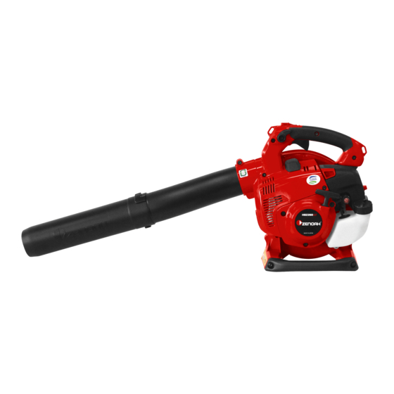
HBZ260EZ
● This instruction manual contains information required when using the
WARNING
● Electrical parts may cause fire or injury if precautions are not followed.
*01-HBZ260EZ_O-M_4ヵ国_GB_CS5_六.indd 1
product, with important precautions for preventing accidents and product
handling information. To ensure safe product use, read this manual
carefully and understand its content before starting to use the product. Be
sure to store this manual in a readily accessible location after reading.
- GB-01 -
OWNER'S MANUAL
BLOWER
115762894 (1511)
Original Instruction
15/11/17 11:31
G
B
Advertisement
Table of Contents

Related Manuals for Zenoah HBZ260EZ


Summary of Contents for Zenoah HBZ260EZ
- Page 1 115762894 (1511) Original Instruction OWNER’S MANUAL BLOWER HBZ260EZ ● This instruction manual contains information required when using the product, with important precautions for preventing accidents and product WARNING handling information. To ensure safe product use, read this manual carefully and understand its content before starting to use the product. Be sure to store this manual in a readily accessible location after reading.
- Page 2 Symbols on the machine The below symbols are indicated on the blower for safe operation and maintenance of the blower. Be sure to comply with the precautions associated with these symbols to prevent operation errors. Display location Symbol Meaning Indicates the fuel port and that the fuel Fuel tank cap type is blended gasoline.
- Page 3 Be sure to read this manual carefully and fully understand its content before use. It is designed to help you make the most of the outstanding performance of your Zenoah product, and ensure the smoothest operation. In addition, be sure to store this manual in a readily accessible location after reading, and refer to it if you have questions in future.
-
Page 4: Table Of Contents
Contents Precautions for Ensuring Correct Use ....Product warning label location and maintenance ........4 Service and Warranty ................5 Main Product Specifications ..............6 Names of Parts ..................7 Standard Accessories ................7 Assembly Blower pipe connection ............8 Fuel ...................... -
Page 5: Precautions For Ensuring Correct Use
Precautions for Ensuring Correct Use Before using the product, read this manual carefully and understand its content to ensure correct product handling. Precautions designed to ensure smooth operation are provided below. Other precautions are provided as needed in the text next to the following warning symbol ■... - Page 6 Precautions for Ensuring Correct Use ■ Clothing/equipment during use ■ Fuel precautions ● Before using the blower, make sure your ● The product’s engine runs clothing is appropriate for outdoor work. o n b l e n d e d g a s o l i n e , Wear a work cap, gloves and appropriate w h i c h c o n t a i n s h i g h l y footwear.
- Page 7 ● When replacing parts or refilling oil, use product. genuine Zenoah parts or designated products. ● To p r e v e n t t h e r i s k o f e l e c t r i c s h o c k , d o n o t...
-
Page 8: Product Warning Label Location And Maintenance
Precautions for Ensuring Correct Use ■ Product warning label location and maintenance [Location] No. 588841601 Flying objects warning Keep at least 15 m (50 ft) away from people Wear gloves Wear protective goggles/ear plugs/mask Fan/rotating part caution Read the owner's manual [Label maintenance] (1) Always keep the warning label clean and undamaged. -
Page 9: Service And Warranty
Have your model name and serial number (see diagram below) ready when making inquiries. If you have any concerns or feedback about the product, technical issues or other points, feel free to contact Zenoah’s authorized dealer. The contact information is given on the back cover of this manual. -
Page 10: Main Product Specifications
Main Product Specifications Name/model Zenoah Handheld Engine Blower HBZ260EZ Body dry weight (*1) [kg] 3.9 (3.7) Total length (mm) External dimensions Total width (mm) (*2) Total height (mm) Fuel tank capacity [L] 0.45 Operating engine speed [rpm] 3000 to 7300... -
Page 11: Names Of Parts
Names of Parts Stop switch Main grip Cruise lever Throttle lever Spark plug Carburetor Choke knob Starter knob Muffler Air cleaner Recoil starter Fuel tank cap Primer pump Fuel tank Sub-grip (also serves as stand) Flat nozzle Middle pipe Air intake guard Round nozzle Standard Accessories Number in... -
Page 12: Assembly
Assembly ■ Blower pipe connection The connection procedure is the same for both the round nozzle and flat N O T E nozzle. Select the nozzle type according to the application. 1. Loosen the fastening screw on the body’s Figure 1 pipe mount. -
Page 13: Fuel
When using genuine ZENOAH two-cycle oil (FD class) 50:1 ........(20 milliliters of oil per liter of gasoline) When using genuine ZENOAH two-cycle oil (FC) 40:1 ........(25 milliliters of oil per liter of gasoline) Blend thoroughly Alternatively, you can use oil of the ‘FD’ JASO performance class mixed in a ratio of 50:1 and blended well. -
Page 14: Fueling The Blower
Fueling the Blower ● Supply fuel to the fuel tank outdoors on flat ground. Keep open flames away and extinguish smoking materials before fueling the blower. ● Always stop engine and wait for it to cool before fueling the blower while working. -
Page 15: Starting The Engine
Starting the Engine ● After fueling the blower, move it at least 3 m (10 ft) away from where it was fueled before starting the engine. Starting the engine where the blower was fueled creates the risk of fire from fuel igniting. DANGER ●... - Page 16 1. Set the cruise lever to the 'Start' position. Figure 4 NOTE The throttle lever also moves to the ‘Start’ Cruise lever position together with the cruise lever. Throttle lever 2. Press and release the pump with a finger Figure 5 repeatedly until fuel appears in the primer Choke knob pump.
-
Page 17: Stopping The Engine
6. Press in the choke knob to open the choke. Figure 7 Choke knob 7. Pull the throttle trigger gradually to make engine speed higher. NOTE This blower has a linkage structur that pulling out choke knob makes Idle speed higher. When pulling out the choke knob once, Idle speed is kept higher even after pressing in the knob. -
Page 18: Operating The Blower
Operating the Blower The engine becomes hot during operation. Even when the engine has cooled to a touchable temperature, extended contact may result in burns. Work should be done in the correct posture to prevent elbows or other body parts WARNING contacting the engine even through clothing. -
Page 19: Operating The Throttle Lever (Air Speed Adjustment)
■ Operating the throttle lever (air speed adjustment) Do not perform operations that seem beyond your skill level. Request help IMPORTANT from your place of purchase. Gradually depressing the throttle lever with your Figure 9 index finger increases the air speed (engine speed). -
Page 20: Blower Work
■ Blower work ● Rocks, litter or other flying objects may strike eyes and cause blindness. Always wear protective goggles. ● If another worker approaches your work area, keep the blower’s throttle at the idling position until you can move a safe distance away. WARNING ●... -
Page 21: Inspecting And Servicing
● Always stop the engine before inspecting or servicing the blower. ● To prevent the risk of accidents or serious injury, never modify the blower or disassemble the engine. The Zenoah warranty is void in the event of failure caused by product modification. -
Page 22: Air Cleaner
■ Air cleaner ● Engine performance drops if the pre-filter or felt filter becomes clogged. Operating the engine with the pre- filter, felt filter, deformed, damaged pre- filter or felt filter will cause abnormal wear inside the engine. IMPORTANT ● After mounting the air cleaner cover, move it lightly by hand to check it will not come off. -
Page 23: Fuel Filter
■ Fuel filter IMPORTANT A clogged fuel filter may cause poor acceleration, or speed fluctuations. After roughly every 25 hours of operation, remove Figure 12 the fuel filter from the fuel tank and remove the dirt from it. If the fuel filter is extremely dirty or clogged, replace it with a new one. -
Page 24: Spark Plug
■ Spark plug To prevent the risk of burns from hot parts, do not touch the spark plug with bare hands immediately after the engine is stopped. CAUTION ● Over-tightening the spark plug may damage the cylinder’s screw thread. Always use the plug wrench (socket wrench) provided to tighten the spark plug. -
Page 25: Cooling Air Passage
■ Cooling air passage Do not insert objects in the cooling air intake during operation. Inserted objects may contact rotating parts, creating a hazard. CAUTION Clogged debris between components such as the cooling air intake and IMPORTANT cylinder fin can cause engine overheating and equipment failure. After roughly every 25 hours of operation, inspect Figure 15 the components around the cooling air intake... -
Page 26: Air Intake
■ Air intake ● Do not operate the blower with the air intake guard removed. Contact with the blower fan could result, causing injury. ● Before starting the blower, check that the air intake guard is properly mounted and undamaged. WARNING ●... -
Page 27: Muffler
■ Muffler ● When inspecting the blower before starting work, check for loose bolts and muffler damage or rust. If the muffler is incorrectly mounted, it may become loose during operation and result in hot exhaust gas being emitted. If exhaust gas leaks out, stop the engine immediately and request inspection CAUTION and repair from your place of purchase. - Page 28 2. Remove the six mounting bolts and remove Figure 19 Engine cover the engine cover. [Fastening torque] 2.0 to 2.5 N·m (20 to 25 kgf-cm) 3. Remove the two mounting bolts and remove Muffler the muffler. [Fastening torque] 7.0 to 9.0 N·m (70 to 90 kgf-cm) Mounting bolt Mounting bolt If the switch cord wiring or throttle lever become disengaged when the engine...
-
Page 29: Engine Adjustment
■ Engine adjustment The carburetor is a precision component that requires specialized knowledge and skill to disassemble and service. If the engine’s condition remains IMPORTANT unsatisfactory after performing the adjustment procedure in this manual, contact your place of purchase. [Idle adjustment screw] Figure 21 This screw adjusts the Idle engine speed when the throttle lever is at the minimum speed setting. -
Page 30: Preparing The Blower For Long-Term Storage
■ Preparing the blower for long-term storage It may cause a fire from igniting fuel. ● Keep open flames away when draining the fuel tank. ● Take care not to spill fuel, and wipe up all fuel that spills. DANGER Note the following precautions when storing the blower. -
Page 31: Troubleshooting
• Contact your place of purchase if the problem persists after taking the corrective measure shown or if the problem is not listed here. • The corrective measures marked by an asterisk (*) require genuine Zenoah parts available from your place of purchase. -
Page 32: Limited Warranty
STRUCTION LISTED IN THE OWNER/OPERATOR MANUAL THE PURCHASER SHALL BEAR COSTS OF TRANS- FOR PROPER USE AND MAINTENANCE OF THE UNITS PORTING THE UNIT TO AND FROM THE ZENOAH DEAL- ACCIDENT MISHANDLING, ALTERATION, ABUSE, IM- PROPER LUBRICATION, USE OF ANY PARTS OR ACCES-...