
Related Manuals for Baxi SH 7 COMPACT


Summary of Contents for Baxi SH 7 COMPACT
- Page 1 Spain Portugal Installation and Service Manual Pressurised domestic installations Solar hydraulic unit SH 7 COMPACT SH 7 COMPACT TOP SH 7 SH 14 SH 7 SIMPLE...
-
Page 2: Dear Customer
Dear Customer, Thank you very much for buying this appliance. Please read through the manual carefully before using the product, and keep it in a safe place for later reference. In order to ensure continued safe and efficient operation we recommend that the product is serviced regularly. Our service and customer service organisation can assist with this. -
Page 3: General Safety Instructions
1 Safety Safety General safety instructions 1.1.1 General safety Peligro This appliance can be used by children aged 8 years and above and persons with reduced physical, sensory or mental capabilities or lack of experience and knowledge if they are given correct supervision or instruction on using the appliance in complete safety and understand the hazards involved. - Page 4 1 Safety Advertencia Do not neglect to service the appliance. Contact a qualified professional or take out a maintenance contract for the annual maintenance of the appliance. Recommendations Advertencia The installation must comply with all the provisions of the regulations (DTU, EN, etc.) governing work and interventions in individual homes, blocks of flats or other buildings.
- Page 5 1 Safety 1.3.3 User's liability To guarantee optimum operation of the system, you must abide by the following instructions: Read and follow the instructions given in the manuals provided with the appliance. Call on a qualified professional to carry out installation and initial commissioning.
-
Page 6: About This Manual
2 About this manual About this manual General This manual is intended for installers of pressurised hydraulic units. Symbols used 2.2.1 Symbols used in the manual This manual uses various danger levels to draw attention to special instructions. We do this to improve user safety, to prevent problems and to guarantee correct operation of the appliance. -
Page 7: Technical Specifications
SH 7 Compact / SH 7 Compact Top Fig.1 Dimensions and connections SH 7 Tab.2 Connections SH 7 Compact / SH 7 Compact Top Compact / SH 7 Compact Top Connection Size Flow pipe to solar installation (lower connection of Dia. - Page 8 3 Technical specifications 3.3.2 SH 7, SH 14 Fig.2 Dimensions and connections SH 7 Tab.3 Connections SH 7 and SH 14 and SH 14 Connection Size Flow pipe to solar installation (lower connection of Dia. 22 solar panels) Safety valve outlet G3/4"...
-
Page 9: Electrical Diagram
3 Technical specifications Electrical diagram Fig.4 Electrical diagram of the SH 7 Compact unit T1 A 100 ... 240 V~ ® DeltaSol IP 20 50-60 Hz R1 16(3) A 240 V~ Te mp . Sensor RC TT R2 1(1) A 240 V~... - Page 10 BLUE BLUE BROWN BA-0000068-02 Importante These electrical diagrams only refer to the SH 7 Compact & SH 7 Compact Top systems Importante The SH 7, SH 14 and SH 7 Simple systems require an external solar control to be connected.
-
Page 11: Characteristic Curve
3 Technical specifications Characteristic curve Fig.6 Characteristic curve of the hydraulic unit 1000 1200 1400 · V [l/h] SH 7 COMPACT TOP SH 7 COMPACT SH 7 SH 7 SIMPLE SH 14 BA-0000055-02 7729335 - 04 - 12052021 Solar hydraulic unit... -
Page 12: Description Of The Product
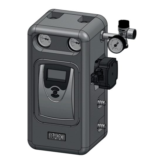
Description of the product General description The SH 7 Compact Top SH 7 Compact, SH 7, SH 14 and SH 7 Simple hydraulic units are a small and compact solution containing all elements required to easily, quickly and conveniently install solar thermal energy systems. - Page 13 4 Description of the product 4.3.2 SH 7, SH 14 Fig.8 Main components of the SH 7 and The SH 7 and SH 14 systems comprise the following main components: SH 14 units Return valve Safety unit Solar circuit pump Outlet valve Flow regulator Air separator...
-
Page 14: Standard Delivery
4 Description of the product Standard delivery Fig.10 Standard delivery Each solar hydraulic unit package contains: Hydraulic unit Safety unit and assembly accessories Documentation pack Importante The final product may differ from the image. BA-0000027-01 Solar hydraulic unit 7729335 - 04 - 12052021... -
Page 15: Before Installation
5 Before installation Before installation Installation regulations Advertencia The system must be installed by a qualified professional in accordance with prevailing local and national regulations. Electrical requirements Tab.5 Electrical information Values Supply voltage 1~230 V/50 Hz Power supply Single phase Choice of the location 5.3.1 Location dimensions... - Page 16 5 Before installation 5.3.3 Installation examples Fig.12 System 1 Standard solar power system with an accumulator for all models of control panel. The solar control compares the temperature difference between the collector sensor S1 and the accumulator sensor S2. If the temperature difference is greater than or equal to the activation value set on the control for the pump R1, the pump starts up and charges the accumulator until it reaches either the value for the shutdown difference...
- Page 17 Fig.15 System 4 BA-0000089-01 Standard solar power system with heating circuit for the SH 7 Compact Top model. The solar system heats a hot water cylinder which serves as a buffer tank. This buffer tank is used to heat the domestic hot water and simultaneously transfer heat to the heating circuit return.
- Page 18 5.3.5 Quantity of antifreeze BAXI heat transfer fluid can be used to fill the installation, in the correct concentration for the minimum foreseeable outdoor temperature in the location. It is recommended that you use a mixture of water and glycol in the following proportions: Tab.7...
- Page 19 5 Before installation Atención The concentration of heat transfer fluid in the installation must never fall below 20%. Advertencia Although it is non-toxic, odourless and biodegradable, it is appropriate to take precautions when handling the product. It is recommended that you use gloves which are resistant to chemical products and wear suitable eye protection when handling the product.
-
Page 20: Installation
6 Installation Installation General The following observations must be taken into account for the hydraulic unit installation: Once all the hydraulic connections have been completed, check the sealing of the entire circuit. It is helpful to protect the collectors from the potential effects of solar radiation once the packaging has been removed, until the installation has been filled. - Page 21 6 Installation Assembly 6.3.1 Assembly of the hydraulic unit Importante All units can be mounted on a wall rather than on the tank, as illustrated below. Importante The solar unit must be installed vertically (flow rate direction from the pump going up towards the collector). This installation position means that the thermometers, pressure gauges and flowmeters are easily visible.
-
Page 22: System Connection
6 Installation 6.3.2 Assembly of the expansion vessel Fig.19 Assembly of the expansion vessel 1. Connect the hydraulic connection to the expansion vessel. 2. Screw on the bracket for the expansion vessel with the screws supplied. 3. Hang the expansion vessel using the intended groove on the hydraulic connection. - Page 23 6 Installation Advertencia If the power cable is damaged, for safety reasons this must only be replaced by the manufacturer, by its after sales department or by qualified personnel. The appliance must be powered with a circuit equipped with a omnipolar switch with a contact opening distance of 3 mm.
- Page 24 6 Installation Filling the installation 6.6.1 General Atención During the start-up process, pay particular attention to cover the collectors, in order to avoid an undesirable increase in pressure. Atención The installation must be filled with the system empty. 6.6.2 Filling the installation Close valves A, B and C before filling the installation.
-
Page 25: Solar Control
7 Solar control Solar control Description of the solar control on the SH 7 Compact 7.1.1 Keys Fig.21 Solar controller The controller is operated using the three keys under the screen: Forwards (+) (selection/setting mode) Back (-) Key 1 is used to move forwards in the menu or to increase values. Key 2 is used to select channels and confirm settings. - Page 26 Collector safety disconnection activated Sensor error Accumulator safety disconnection activated Parameter Setting mode Description of the solar control on the SH 7 Compact Top 7.2.1 Keys and dial The controller is operated using the 2 keys and the dial located under the screen: Fig.24...
- Page 27 7 Solar control Tab.9 Premium solar control box operating statuses Colour Permanently lit Flashing Green All correct Manual mode: One relay at least in manual mode Broken sensor cable, short-cir cuit on the cable of one sensor, monitor flow rate, overpressu re, low pressure Yellow Holiday mode ON...
-
Page 28: Solar Pump
8 Solar pump Solar pump Operating data The pump UPM3 Solar is a high-efficiency pump designed to function with and without the PWM signal, therefore enabling the following curves: 3 Constant curves (functioning without PWM signal) One PWM curve with solar profile C (stopping without PWM signal) Importante The pump is preset to curve with profile C PWM by default. - Page 29 8 Solar pump Tab.11 Sequence of error alarms Pump ope Indications Action ration Attempt res Wait and Rotor blo tart every unblock the cked 1.33 se shaft conds Warning Voltage Check the only, pumps supplied too voltage sup continues to plied The pump has stopped...
- Page 30 8 Solar pump Pump profile Tab.14 Electrical data, 1~230 V/50 Hz Speed Units UPM3 15–75 UPM3 15–145 Min. - Max. 2 - 45 2 - 60 Min. - Max. 0.04 - 0.48 0.04 - 0.58 Tab.15 Data in line with the selected curve Selected curve Units UPM3 15–75...
- Page 31 8 Solar pump Fig.27 Pump profile UPM3 15–145 [kPa] 1.2 1.4 2.4 2.6 Q [m³/h] Q [l/s] 1.2 1.4 2.4 2.6 Q [m³/h] BA-0000154-01 7729335 - 04 - 12052021 Solar hydraulic unit...
-
Page 32: Checklist Before Commissioning
4. Check the pressure shown on the unit's pressure gauge. 5. Check the electrical connections. 6. Check that there is an earth connection and the corresponding earth connection circuit. Commissioning procedure for SH 7 Compact 9.3.1 Settings Once the filling procedure is complete, the system must be connected to the power supply. - Page 33 9 Commissioning System Fig.30 System Select the solar system required. SIST Maximum accumulator temperature Fig.31 Maximum accumulator temperature Adjust the desired maximum temperature of the accumulator. AMAX Connection temperature for the auxiliary heating Fig.32 Connection temperature Set the required connection temperature. CA1O Shutdown temperature for the auxiliary heating Fig.33...
- Page 34 9 Commissioning Channel Meaning Factory set ting Drainback option ORSI System cooling option Accumulator cooling option Option thermostat 1 CA1O Connection temperature thermostat 1 40 ºC CA1F Shutdown temperature thermostat 1 45 ºC Thermostat 1 cooling t1O1 Thermostat 1 connection time 1 07:00 t1F1 Thermostat 1 shutdown time 1...
- Page 35 9 Commissioning Units Fig.36 Temperature unit Select the unit of temperature. Fig.37 Flow rate unit Select the flow rate unit. Fig.38 Pressure unit Select the unit of pressure. Fig.39 Energy unit Select the unit of energy. Switching between summer and winter time Fig.40 Switching between summer and Enable or disable automatic switching between summer and winter time.
- Page 36 9 Commissioning Time Fig.41 Time Set the clock. Set the hours first, then the minutes. Date Fig.42 Date Adjust today's date. Set today's date by setting the year first, then the month and the day. Selection: System or diagram Fig.43 Selection: System or diagram Select to configure the controller with a system.
- Page 37 9 Commissioning 9.4.2 Premium factory setting values Solar Tab.18 Factory values on the solar menu Basic settings System Collector Min. coll. temp. 10 °C Safety limit 130 °C Accumulator ΔT 6.0K ΔT 4.0K ΔT 10.0K nom. Acc. nom. temp. 60 °C Acc.
- Page 38 9 Commissioning Inputs PT1000 PT1000 None Type Min. 5 l/min Max. 100 l/min None Tab.22 Factory values on the outputs menu Outputs Signal 0-10 V Output Type Solar Min. speed Max. speed 100% Signal Standard Min. speed 100% Max. speed 100% Free Signal...
-
Page 39: Standard Inspection And Maintenance Operations
10 Maintenance 10 Maintenance 10.1 General Advertencia Maintenance work must be carried out by a qualified professional. Advertencia Failure to service the system will void the warranty. Advertencia Use only genuine spare parts. Peligro There is always a risk that they pump could become extremely hot, depending on the operating conditions of the pump as well as the installation (temperature of the flow medium). -
Page 40: Troubleshooting
11 Troubleshooting 11 Troubleshooting 11.1 General malfunctions Peligro de electrocución Always disconnect the unit from the power supply before removing the cover from the solar control. Tab.26 General malfunctions Fault Possible cause Solution The collector field The surface of Clean the surface of the collectors. installation does the collectors is not heat the ac... -
Page 41: Decommissioning Procedure
12 Decommissioning 12 Decommissioning 12.1 Decommissioning procedure Fig.47 Switching off the power supply If you need to decommission the SH DB system, either temporarily or permanently, proceed as follows: 1. Switch off the power supply to the system. 2. Wait until the fluid has drained out of the installation and is stored in the SH DB system. -
Page 42: Disposal And Recycling
13 Disposal 13 Disposal 13.1 Disposal and recycling Fig.48 Recycling MW-3000179-03 Fig.49 Switching off the power supply Advertencia Removal and disposal of the system must be carried out by a qualified installer in accordance with local and national regulations. Disassemble the system as follows: 1. - Page 43 © Copyright All technical and technological information contained in these technical instructions, as well as any drawings and technical descriptions supplied, remain our property and shall not be multiplied without our prior consent in writing. Subject to alterations.
- Page 44 7729335 - 04 - 12052021 7729335-04...