Table of Contents
Advertisement
Garage Door Opener
Series 5100 – 1/2HP
(Includes Model 7200)
Series 2100 – 1/3HP
Series 3000 – 1/2HP
Please read this manual and the enclosed safety materials carefully!
Fasten the manual near the garage door after installation.
The door WILL NOT CLOSE unless the Protector System
properly aligned
Periodic checks of the opener are required to ensure safe operation.
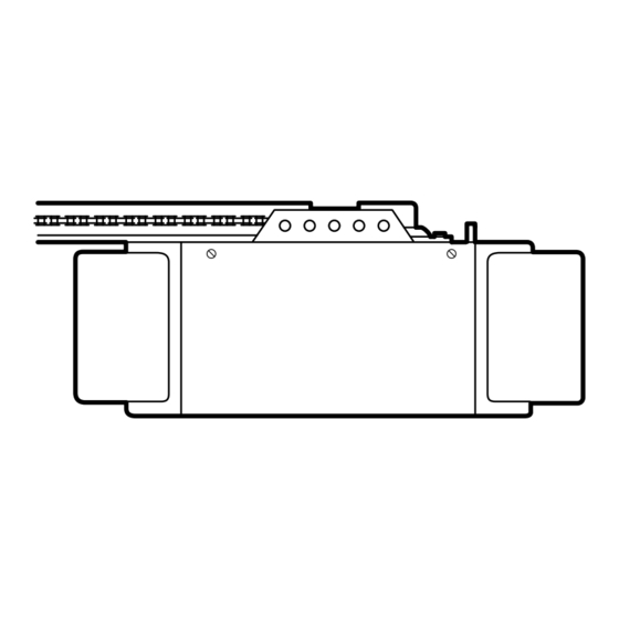
The model number label is located on the front end panel of your opener as
shown.
OWNER'S MANUAL
For Residential Use Only
The Chamberlain Group, Inc.
A DUCHOSSOIS ENTERPRISE
845 Larch Avenue
Elmhurst, Illlinois 60126-1196
Complies with UL 325
®
Regulations effective
®
January 1, 1993.
Series 4100 – 1/2HP
(Includes Model 710WHC)
Series 1100 – 1/4HP
®
is connected and
®
®
Advertisement
Table of Contents

Related Manuals for Chamberlain Series 1100


Summary of Contents for Chamberlain Series 1100
- Page 1 The Chamberlain Group, Inc. A DUCHOSSOIS ENTERPRISE 845 Larch Avenue Elmhurst, Illlinois 60126-1196 Complies with UL 325 Regulations effective ® January 1, 1993. ® ® Series 4100 – 1/2HP (Includes Model 710WHC) Series 1100 – 1/4HP ® is connected and...
-
Page 2: Table Of Contents
Contents A review of safety alert symbols...2 You'll need tools...3 Safety information regarding garage door locks and ropes...3 Testing your garage door for sticking, binding and balance...3 Illustration of sectional door installation ...4 Illustration of one-piece door installation...5 Carton inventory...6 Hardware inventory...7 Assembly section –... -
Page 3: You'll Need Tools
During assembly, installation and adjustment of the opener, instructions will call for hand tools shown below. Carpenter's Level Stepladder WARNING An unbalanced garage door might not reverse when required and someone under the door could be seriously injured or killed. If your garage door binds, sticks or is out of balance, call for professional garage door service. -
Page 4: Illustration Of Sectional Door Installation
Before you begin, survey your garage area to see whether any of the conditions below apply to your installation. Horizontal and vertical reinforcement is needed for lightweight garage doors (fiberglass, steel, aluminum, door with glass panels, etc.). See page 24 for details. Header Wall Safety Reversing Sensor Based on your particular requirements, there are... -
Page 5: Illustration Of One-Piece Door Installation
ONE-PIECE Door Installation Before you begin, survey your garage area to see whether any of the conditions below apply to your installation. Header Wall Gap between floor and bottom Safety of door must not exceed 1/4". Reversing Sensor Based on your particular requirements, there are several installation steps which might call for materials and/or hardware not included in the carton. -
Page 6: Carton Inventory
7. Models 5100 (1) & 5100-2 (2) Multi-Function Remote Control Transmitter Remote Control Transmitter Models 4100, 3000, 2100, 1100 (1) 4100-2 & 710-2 (2) Single-Function Remote Control Transmitter Models 5100 & 5100-2 (2) Models 4100 & 710 (1) Light Lens Model 3000 &... -
Page 7: Hardware Inventory
Group all hardware found in all packages contained in the rail and opener cartons into the three kits illustrated below. Assembly Hardware Kit 41A2848 Hex Screw Washered Screw 5/16"-18x7/8" (3) 5/16"-18x1/2" (2) (mounted in opener) Trolley Threaded Shaft (1) Hex Screw 5/16"-18x7/8"... -
Page 8: Assembly Section: Pages
Hex Screws Assembly Section: Pages 8 – 11 5/16"-18x7/8" To avoid installation difficulties, do not run the garage door opener until instructed to do so. Assembly Step 1 Cable Pulley Bracket Assemble the T-rail & Attach the Cable Pulley Bracket •... -
Page 9: Install Trolley
Assembly Step 2 Install the Trolley on the T-rail • Attach the threaded shaft to the trolley with the lock washer and nuts as shown. Lock Washer 5/16" Outer Nut 5/16" Trolley Temporary Stop Screwdriver Assembly Step 3 Fasten the T-rail to the Opener •... -
Page 10: Install Chain/Cable
Check to make sure the chain is not twisted. • Remove the screwdriver. Install Chain & Cable In This Direction stall Chain & Cable Chamberlain '92 Install Chain & Cable 8/22/90 - 3/6/92 In This Direction Sprocket Cover... -
Page 11: Tighten The Chain And Cable
Assembly Step 5 Tighten the Chain & Cable • Spin the inner nut and lock washer down the threaded shaft, away from the trolley. • To tighten the chain, turn outer nut in the direction shown. As you turn the nut, keep the chain from twisting. -
Page 12: Installation Section: Pages
Installation Section: Pages 12 – 27 Installation Step 1 Determine Header Bracket Location Installation procedures vary according to garage door types. Follow the instructions which apply to your door. SECTIONAL Door and ONE-PIECE Door With Track Guideline Header Wall • Open your door to the highest point of travel as shown. -
Page 13: One-Piece Door
Read the Safety Instructions on page 12. They also apply to doors without tracks. • Close the door and mark the inside vertical centerline of your garage door. Extend the line onto the header wall above door. If headroom clearance is minimal, you can install the header bracket on the ceiling. -
Page 14: Install The Header Bracket
Installation Step 2 Install the Header Bracket • Center the bracket on the vertical guideline with the bottom edge of the bracket on the horizontal line as shown (with the arrow pointing toward the ceiling). Header Wall Header Bracket Structural Support 2"... -
Page 15: Attach The T-Rail To Header Bracket
Installation Step 3 Attach the T-rail to the Header Bracket Header Wall Header Bracket Cable Pulley Bracket Garage Door • Position the opener on the garage floor below the header bracket. Use packing material as a protective base. If the door spring is in the way you'll need help. Have someone hold the opener securely on a temporary support to allow the T-rail to clear the spring. -
Page 16: Position The Opener
Installation Step 4 Position the Opener Follow instructions which apply to your door type as illustrated. SECTIONAL Door & ONE-PIECE Door with Track A 2x4 laid flat is convenient for setting an ideal door-to-T-rail distance. • Raise the opener onto a stepladder. You will need help at this point if the ladder is not tall enough. -
Page 17: Hang The Opener
Installation Step 5 Hang the Opener Two representative installations are shown. Yours may be different. Hanging brackets should be angled, Figure 1, to provide rigid support. On finished ceilings, Figure 2, attach a sturdy metal bracket to structural supports before installing the opener. -
Page 18: Install The Door Control
Installation Step 6 Install the Door Control • Strip 1/4" of insulation from one end of the bell wire; connect the wire to the two screw terminals on the back of the Door Control: white to 2 and white/red to 1. •... -
Page 19: Install The Lights And Lenses
Snap bottom tabs of lens into panel slots. Retighten top panel screws to secure lens. Install the Lens(es) (All Other Models) (Except Model 1100 - No Lens) • See Figure 2. • Slide lens into guides. Snap bottom tabs into lens slots. -
Page 20: Electrical Requirements
Installation Step 9 Electrical Requirements To reduce the risk of electric shock, your garage door opener has a grounding type plug with a third grounding pin. This plug will only fit into a grounding type outlet. If the plug doesn't fit into the outlet you have, contact a qualified electrician to install the proper type outlet. -
Page 21: The Protector System
Information you'll need before you begin the installation of the safety reversing sensor. The safety reversing sensor must be connected and aligned correctly before the garage door opener will move in the down direction. This is a required safety device and cannot be disabled. Installation procedures are the same for sectional and one-piece doors. -
Page 22: Install The Safety Reversing Sensor
Installation Step 10 Install the Safety Reversing Sensor Figures 2 and 3 show assembly of brackets and "C" wrap based on the recommended installation of the sensors on each side of the garage door as shown on page 21. However, Figures 4 and 5 are variations which may fit your installation requirements better. - Page 23 • Insert the wire connector into each sensor and push until you hear a click, Figure 6. The white tab on the sensor should be flush with the back of the connector. – Finished Ceiling – Bell Wire Invisible Light Beam Protection Area Sensor •...
-
Page 24: Fasten Door Bracket (Sectional Door)
Installation Step 11 Fasten Door Bracket Follow instructions which apply to your door type as illustrated below or on page 25. A horizontal brace should be long enough to be secured to 2 vertical supports. A vertical brace should cover the height of the top panel. The illustration shows one piece of angle iron as the horizontal brace. -
Page 25: Fasten Door Bracket (One-Piece Door)
All ONE-PIECE Door Installation Procedure Please read and comply with the warnings and reinforcement instructions on page 24. They apply to one-piece doors also. Header Wall 2x4 Support Header Bracket Door Bracket • Center the bracket on the top of the door, in line with the header bracket as shown. -
Page 26: Connect Door Arm To Trolley (Sectional Door)
Installation Step 12 Connect Door Arm to Trolley Follow instructions which apply to your door type as illustrated below and on page 27. Make sure garage door is fully closed. Pull the manual release handle to disconnect the outer trolley from the inner trolley. -
Page 27: Connect Door Arm To Trolley (One-Piece Door)
Assemble the Door Arm: • Fasten the straight and curved door arm sections together to the longest possible length (with a 2 or 3 hole overlap). • With the door closed, connect the straight door arm section to the door bracket with a clevis pin. •... -
Page 28: Adjustment Section: Pages
Adjustment Section: Pages 28 – 30 Adjustment Step 1 Adjust the UP and DOWN Limits Do not make any limit adjustments until the Safety Reversing Sensors are completely installed. Limit adjustment settings regulate the points at which the door will stop when moving up or down. The door will stop in the up direction if anything interferes with door travel. -
Page 29: Force Adjustments
Adjustment Step 2 Adjust the Force Force adjustment controls are located on the back panel of the opener. Force adjustment settings regulate the amount of power required to open and close the door. The door will stop in the up direction if anything interferes with its travel. -
Page 30: Test The Protector System
Adjustment Step 3 Test the Protector System • Press the remote control push button to open the door. • Place the opener carton in the path of the door. • Press the remote control push button to close the door. The door will not move more than an inch, and the opener light(s) will flash for 5 seconds. -
Page 31: Operation Safety Instructions
IMPORTANT SAFETY INSTRUCTIONS WARNING To reduce the risk of severe injury or death to persons: 1. READ AND FOLLOW ALL INSTRUCTIONS. 2. Do not permit children either to operate or to play with the opener. Keep remote control in a location inaccessible to children. -
Page 32: Operation Of Your Opener
Activate the opener with any of the following: • The Remote Control. Hold push button down until the door starts to move. • The Door Control. Hold push bar or button down until the door starts to move. • The Outside Keylock or Keyless Entry. (See Accessories) When the opener is activated with the safety reversing sensor installed and correctly aligned:... -
Page 33: Receiver And Remote Control Programming
Models having multi-function remote controls will activate when the large button on remote(s) is pressed. The multi-function remote(s) can also activate additional garage door openers and/or light control models 874CB and 872CB. Below are instructions for programming your opener... -
Page 34: Having A Problem
Situation Probable Cause & Solution 1. Does the opener have electric power? Plug a lamp into the outlet. If it doesn't light, The opener doesn't check the fuse box or the circuit breaker. (Some outlets are controlled by a wall switch.) operate from either the door control or 2. -
Page 35: Having A Problem
Situation Probable Cause & Solution The door opens but 1. If the opener lights blink, check the safety reversing sensor. See page 23. won't close: 2. If the opener lights do not blink and it is a new installation, check the down force. See Adjustment Step 2, page 29. -
Page 36: Repair Parts, Rail Assembly
Rail Assembly Parts Installation Parts LO CK LIG HT KEY PART NO. NO. DESCRIPTION 41A4251-3A Multi-function door control panel 41A4166 Lighted door control button 10A14 12V battery 29C128 Transmitter visor clip 41A3888-3 Multi-function remote control housing & screw only (no circuit board) 41A3984-5 Single-function remote control housing &... -
Page 37: Repair Parts, Opener Assembly
Opener Assembly Parts (Series 5100) (Series 4100, 2100, 1100 & 710WHC) LIMIT SWITCH (Down) ASSEMBLY Contact Brown Wire Drive Gear Center Limit (Up) Yellow Contact Contact KEY PART DESCRIPTION 31D380 Sprocket cover 41C4220A Gear and sprocket assembly Complete with: Spring washer,... -
Page 38: Accessories
Accessories Available for your Opener 7702CB Outside Quick Release: Required for a garage with NO access door. 760CB Outside Keylock: Opens the garage door automatically from outside when remote control is not handy. 7704CB 8 foot Rail Extension Kit: To allow an 8 foot door to open fully. -
Page 39: Index
Access Door/Outside Quick Release Accessory...4, 5 Chain Tension ...4, 5, 11 Electrical Safety Warnings...2, 20, 31 Garage Door Testing for balance, binding and sticking...3, 28, 31 Determining high point of travel: Sectional door...12 One-piece door ...13 Disabling existing locks...3, 11 Force Controls Adjustment procedures...29 Problems that might require force adjustments ...34, 35... -
Page 40: How To Order Repair Parts
CHAMBERLAIN GARAGE DOOR OPENER ONE-YEAR LIMITED WARRANTY The Chamberlain Group, Inc. (“Seller”) warrants to the first retail purchaser of this product that it is free from defect in materials and/or workmanship for a period of one year from the date of purchase. The proper operation of this product is dependent on your compliance with the Owner’s Manual instructions regarding installation, operation, maintenance and testing.